EP1109241A2 - Flow channels in current collector plates for fuel cells - Google Patents
Flow channels in current collector plates for fuel cells Download PDFInfo
- Publication number
- EP1109241A2 EP1109241A2 EP00122709A EP00122709A EP1109241A2 EP 1109241 A2 EP1109241 A2 EP 1109241A2 EP 00122709 A EP00122709 A EP 00122709A EP 00122709 A EP00122709 A EP 00122709A EP 1109241 A2 EP1109241 A2 EP 1109241A2
- Authority
- EP
- European Patent Office
- Prior art keywords
- leg
- gas
- segment
- pressure
- medial
- Prior art date
- Legal status (The legal status is an assumption and is not a legal conclusion. Google has not performed a legal analysis and makes no representation as to the accuracy of the status listed.)
- Granted
Links
Images


Classifications
-
- H—ELECTRICITY
- H01—ELECTRIC ELEMENTS
- H01M—PROCESSES OR MEANS, e.g. BATTERIES, FOR THE DIRECT CONVERSION OF CHEMICAL ENERGY INTO ELECTRICAL ENERGY
- H01M8/00—Fuel cells; Manufacture thereof
- H01M8/02—Details
- H01M8/0202—Collectors; Separators, e.g. bipolar separators; Interconnectors
- H01M8/0247—Collectors; Separators, e.g. bipolar separators; Interconnectors characterised by the form
-
- H—ELECTRICITY
- H01—ELECTRIC ELEMENTS
- H01M—PROCESSES OR MEANS, e.g. BATTERIES, FOR THE DIRECT CONVERSION OF CHEMICAL ENERGY INTO ELECTRICAL ENERGY
- H01M8/00—Fuel cells; Manufacture thereof
- H01M8/02—Details
- H01M8/0202—Collectors; Separators, e.g. bipolar separators; Interconnectors
- H01M8/0258—Collectors; Separators, e.g. bipolar separators; Interconnectors characterised by the configuration of channels, e.g. by the flow field of the reactant or coolant
- H01M8/0263—Collectors; Separators, e.g. bipolar separators; Interconnectors characterised by the configuration of channels, e.g. by the flow field of the reactant or coolant having meandering or serpentine paths
-
- H—ELECTRICITY
- H01—ELECTRIC ELEMENTS
- H01M—PROCESSES OR MEANS, e.g. BATTERIES, FOR THE DIRECT CONVERSION OF CHEMICAL ENERGY INTO ELECTRICAL ENERGY
- H01M8/00—Fuel cells; Manufacture thereof
- H01M8/02—Details
- H01M8/0202—Collectors; Separators, e.g. bipolar separators; Interconnectors
- H01M8/0267—Collectors; Separators, e.g. bipolar separators; Interconnectors having heating or cooling means, e.g. heaters or coolant flow channels
-
- H—ELECTRICITY
- H01—ELECTRIC ELEMENTS
- H01M—PROCESSES OR MEANS, e.g. BATTERIES, FOR THE DIRECT CONVERSION OF CHEMICAL ENERGY INTO ELECTRICAL ENERGY
- H01M8/00—Fuel cells; Manufacture thereof
- H01M8/24—Grouping of fuel cells, e.g. stacking of fuel cells
- H01M8/2465—Details of groupings of fuel cells
- H01M8/2483—Details of groupings of fuel cells characterised by internal manifolds
-
- F—MECHANICAL ENGINEERING; LIGHTING; HEATING; WEAPONS; BLASTING
- F28—HEAT EXCHANGE IN GENERAL
- F28F—DETAILS OF HEAT-EXCHANGE AND HEAT-TRANSFER APPARATUS, OF GENERAL APPLICATION
- F28F2210/00—Heat exchange conduits
- F28F2210/10—Particular layout, e.g. for uniform temperature distribution
-
- Y—GENERAL TAGGING OF NEW TECHNOLOGICAL DEVELOPMENTS; GENERAL TAGGING OF CROSS-SECTIONAL TECHNOLOGIES SPANNING OVER SEVERAL SECTIONS OF THE IPC; TECHNICAL SUBJECTS COVERED BY FORMER USPC CROSS-REFERENCE ART COLLECTIONS [XRACs] AND DIGESTS
- Y02—TECHNOLOGIES OR APPLICATIONS FOR MITIGATION OR ADAPTATION AGAINST CLIMATE CHANGE
- Y02E—REDUCTION OF GREENHOUSE GAS [GHG] EMISSIONS, RELATED TO ENERGY GENERATION, TRANSMISSION OR DISTRIBUTION
- Y02E60/00—Enabling technologies; Technologies with a potential or indirect contribution to GHG emissions mitigation
- Y02E60/30—Hydrogen technology
- Y02E60/50—Fuel cells
Definitions
- This invention relates to PEM fuel cells and more particularly to the reactant flow fields therefor.
- PEM fuel cells have been proposed as a power source for many applications.
- PEM fuel cells include, in each cell thereof, a so-called “membrane-electrode-assembly" (hereafter MEA) comprising a thin (i.e., ca. 0.0015-0.007 inch), proton-conductive, polymeric, membraneelectrolyte having an anode electrode film (i.e., ca. 0.002 inch) formed on one face thereof, and a cathode electrode film (i.e., ca. 0.002 inch) formed on the opposite face thereof.
- MEA membrane-electrode-assembly
- Such membrane-electrolytes are well known in the art and are described in such U.S.
- membrane-electrolytes are made from ion-exchange resins, and typically comprise a perfluoronated sulfonic acid polymer such as NAFIONTM available from the E.I. DuPont de Nemours & Co.
- the anode and cathode films typically comprise (1) finely divided carbon particles, very finely divided catalytic particles supported on the internal and external surfaces of the carbon particles, and proton conductive material (e.g., NAFIONTM) intermingled with the catalytic and carbon particles, or (2) catalytic particles, sans carbon, dispersed throughout a polytetrafluoroethylene (PTFE) binder.
- proton conductive material e.g., NAFIONTM
- PTFE polytetrafluoroethylene
- the MEA is sandwiched between sheets of porous, gas-permeable, conductive material, known as a "diffusion layer", which press against the anode and cathode faces of the MEA and serve as (1) the primary current collectors for the anode and cathode, and (2) mechanical support for the MEA.
- Suitable such primary current collector sheets comprise carbon or graphite paper or cloth, fine mesh noble metal screen, and the like, through which the gas can move to contact the MEA, as is well known in the art.
- the thusly formed sandwich is pressed between a pair of electrically conductive plates which serve as secondary current collectors for collecting the current from the primary current collectors and conducting current between adjacent cells (i.e., in the case of bipolar plates) internally of the stack, and externally of the stack in the case of monopolar plates at the ends of the stack.
- the secondary current collecting plates each contain at least one so-called "flow field” that distributes the fuel cell's gaseous reactants (e.g., H 2 and O 2 /air) over the surfaces of the anode and cathode.
- the flow field includes a plurality of lands which engage the primary current collector and define therebetween a plurality of flow channels through which the gaseous reactants flow between a supply manifold at one end of a flow channel and an exhaust manifold at the other end of the channel.
- Serpentine flow channels are known and connect the supply and exhaust manifolds only after having made a number of hairpin turns and switch backs such that each leg of the serpentine flow channel borders at least one other leg of the same serpentine flow channel (e.g., see U.S. patent 5,108,849).
- the pressure drop between the supply manifold and the exhaust manifold is of considerable importance in designing a fuel cell.
- One of the ways of providing a desirable pressure drop is to vary the length of the flow channels extending between the supply and exhaust manifolds.
- Serpentine channels have been used heretofore to vary the length of the flow channels.
- Serpentine channels are designed to allow some limited gas movement between adjacent legs of the same channel via the diffusion layer so as to expose the MEA confronting the land separating the legs to reactant.
- gas can flow from an upstream leg of the channel (i.e. where pressure is higher) to a downstream leg of the same channel (i.e. where gas pressure is lower) by moving through the diffusion layer over/under the land that separates the upstream leg from the downstream leg of the flow channel.
- a flow channel configuration that has relatively low pressure drop between adjacent legs of the same channel and between the ends of the legs and adjacent supply/exhaust manifolds.
- the present invention overcomes the aforesaid prior art problem by providing a flow channel that is subdivided into a plurality of serially-arranged segments or stages, each of which segments has its own serpentine configuration whose legs are relatively short.
- very little pressure drop exists (a) between adjacent legs of the same channel, (b) between the ends of the legs and adjacent bridging sections of the same channel, or (c) manifolds adjacent the ends of the legs.
- the present invention is an improvement to PEM fuel cells of the general type which comprise (1) a proton exchange membrane having opposing cathode and anode faces on opposite sides thereof, (2) a gas-permeable, electrically-conductive cathode current collector engaging the cathode face, (3) a gas-permeable electrically-conductive anode current collector engaging the anode face, and (4) a current-collecting plate engaging at least one of the gas-permeable collectors and defining a gas flow field that confronts that gas-permeable collector.
- the improvement involves a flow field that comprises a plurality of lands that engage the current collector and define a plurality of substantially equal-length serpentine gas flow channels, each of which comprises a plurality of serially-linked serpentine segments that lie in a first general direction extending between a gas supply manifold and gas exhaust manifold.
- Each segment has: an inlet leg for receiving gas into the segment at a first pressure; an exit leg for exhausting from said segment at a second pressure less than said first pressure; and at least one medial leg intermediate the inlet and exit legs.
- medial legs may be used to increase the pressure drop from one end of a channel to the other.
- the inlet, exit and medial leg(s) for each channel at least in part border at least one other leg of the same channel.
- each channel includes at least three serpentine segments serially arranged in the general direction extending between the supply and exhaust manifolds.
- a bridging section of each channel extends in a second general direction transverse the first general direction, and couples the exit leg of one segment to the inlet leg of the next-adjacent segment downstream of the one segment (i.e. in the direction of the gas flow through the channel).
- the end of the medial leg closest to the inlet leg of the one segment i.e.
- adjacent channels are mirror images of each other such that the inlet legs of adjacent channels border each other and the exit legs of adjacent channels border each other, but the inlet legs do not border the exit legs for the same reasons as set forth in copending United States patent application USSN 09/016127 filed January 30, 1998 in the name of Jeffrey Rock, and assigned to the assignee of the present application.
- FIG. 1 depicts a two cell, bipolar, PEM fuel cell stack having a pair of membrane-electrode-assemblies (MEAs) 4 and 6 separated from each other by an electrically conductive, liquid-cooled, bipolar plate 8.
- MEAs 4 and 6, and bipolar plate 8 are stacked together between stainless steel clamping plates 10 and 12, and monopolar end contact plates 14 and 16.
- fuel and oxidant gases i.e., H 2 & O 2
- Nonconductive gaskets 26, 28, 30, and 32 provide seals and electrical insulation between the several plates of the fuel cell stack.
- Porous, gas permeable, electrically conductive sheets 34, 36, 38 and 40 known as diffusion layers, press up against the electrode faces of the MEAs 4 and 6 and serve as primary current collectors for the electrodes as well as mechanical supports for the MEAs, especially at locations where the MEAs 4 and 6 span flow channels in the flow field and are otherwise unsupported.
- Suitable primary current collectors include carbon/graphite paper/cloth, fine mesh noble metal screens, open cell noble metal foams, and the like which conduct current from the electrodes while allowing gas to pass therethrough to reset on the electrodes.
- the end contact elements 14 and 16 press up against the primary current collectors 34 and 40 respectively, while the bipolar plate 8 presses up against the primary current collector 36 on the anode face of MEA 4, and against the primary current collector 38 on the cathode face of MEA 6.
- Oxygen may be supplied to the cathode side of the fuel cell stack from a storage tank 46 via appropriate supply plumbing 42, while hydrogen may be supplied to the anode side of the fuel cell from a storage tank 48, via appropriate supply plumbing 44.
- the O 2 tank 46 is eliminated and air is supplied to the cathode side from the ambient.
- the H 2 tank 48 is eliminated and hydrogen supplied to the anode from a reformer or other form of fuel processor which catalytically generates hydrogen from methanol or a liquid hydrocarbon (e.g., gasoline).
- Exhaust plumbing (not shown) for both the H 2 and O 2 /air sides of the MEAs is also provided for removing H 2 depleted anode gas from the anode flow field and O 2 -depleted cathode gas from the cathode flow field.
- Additional plumbing 50, 52 and 54 is provided for supplying liquid coolant to the bipolar plate 8 and end plates 14 and 16, as may be needed. Appropriate plumbing for exhausting coolant from the plate 8 and end plates 14 and 16 is also provided, but not shown.
- FIG. 2 is an isometric, exploded view of a bipolar plate 56, first primary porous current collector 57, MEA 59 and second primary porous current collector 61 as they are stacked together in a fuel cell.
- a second bipolar plate (not shown) would underlie the second primary current collector 61 to form one complete cell.
- another set of primary current collectors and MEA (not shown) will overlie the upper sheet 58.
- the bipolar plate 56 comprises a first exterior metal sheet 58, a second exterior metal sheet 60, and an optional interior spacer metal sheet 62 which is brazed interjacent the first metal sheet 58 and the second metal sheet 60.
- the metal sheets 58, 60 and 62 are made as thin as possible (e.g., about 0.002-0.02 inches thick), may be formed by stamping, by photo etching (i.e., through a photolithographic mask) or any other conventional process for shaping sheet metal.
- the external sheet 58 is formed so as to provide a reactant gas flow field characterized by a plurality of lands 64 which define therebetween a plurality of serpentine gas flow channels 66 through which the fuel cell's reactant gases (i.e., H 2 or O 2 ) flow in a tortuous path from near one edge 68 of the bipolar plate to near the opposite edge 70 thereof.
- the lands 64 press against the primary current collectors 61 which, in turn, press against the MEA 59.
- current flows from the primary current collector through the lands 64 and thence through the stack.
- the reactant gas is supplied to channels 66 from a header or supply manifold groove 72 that lies adjacent the edge 68 of the plate 56 at one end of the flow field, and exits the channels 66 via an exhaust manifold groove 74 that lies adjacent the opposite edge 70 of the fuel cell at the other end of the flow field.
- the supply and exhaust manifolds could lie adjacent the same edge (i.e. 68 or 70) of the plate 56.
- the underside of the metal sheet 58 includes a plurality of ridges (not shown) which define therebetween a plurality of grooves (not shown) through which coolant passes during the operation of the fuel cell.
- Metal sheet 60 is similar to sheet 58.
- the internal (i.e., coolant side) of sheet 60 is shown in Figure 2.
- the coolant side of the flow field includes a plurality of ridges (not shown) defining therebetween a plurality of grooves (not shown) through which coolant flows from one edge 69 of the bipolar plate to the opposite edge 71.
- the external side of the sheet 60 will have a plurality of lands (not shown) thereon defining a plurality of channels (not shown) through which the reactant gases pass.
- An interior metal spacer sheet 62 is interjacent the exterior sheets 58 and 60 and includes a plurality of apertures 84 therein to permit coolant to flow between the grooves on the coolant-side of sheet 60 and the grooves on the coolant-side of sheet 58 thereby breaking laminar boundary layers and affording turbulence, and hence more effective heat exchange with the inside faces of the exterior sheets 58 and 60 respectively.
- the several sheets 58, 60 and 62 are preferably brazed together.
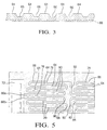
- Figure 3 is a sectioned view in the direction 3-3 of the plate 58 of Fig 2 and shows a plurality of lands 64, reactant flow channels 66 defined by the lands 64, and cooling grooves 68 on the underside of plate 58 for flowing coolant in a direction transverse the direction of reactant flow in channels 66.
- Figure 4 best depicts a cathode flow field configuration in accordance with the present invention, and is a two dimensional view of the plate 58 of Figure 2. See also Figure 5 for a blow-up of the circled portion of Figure 4.
- the flow field comprises a plurality of flow channels 66a-66j connected at one end to an inlet supply manifold 72 that distributes a gaseous reactant (e.g. air) to the flow channels 66a-66j, and at the other end to an exhaust manifold 74 for collecting the gaseous reactant exiting the flow channels 66a-66j.
- a gaseous reactant e.g. air
- Each flow channel 66a-66j comprises a plurality of segments A-E linked to each other, and extending in the general direction between the inlet supply and exhaust manifolds such that gas entering a given channel 66a-66j from the inlet supply manifold 72 flows through all of the segments A-E thereof, in sequence until it exits the flow channels 66a-66j into the exhaust manifold 74.
- Each segment A-E has a serpentine configuration of its own and comprises an inlet leg 76 through which gas flows into a segment A-E, an exit leg 78 through which gas flows out of the segment A-E, and at least one medial leg 80 lying between the inlet and exit legs 76 and 78 respectively.
- Each leg i.e.
- inlet, medial or exit borders at least one other leg of the same channel.
- the medial legs border two legs of the same channel.
- Reverse turns 82, 86, 88 and 90 at each end of the medial leg(s) 80 connect that medial leg 80 to the next adjacent leg(s) of the same flow channel whether it be to an inlet leg 76, an exit leg 78 or another medial leg 80.
- Each serpentine segment A-E is connected to the next segment in the series by a bridging section 92 that connects the exit leg of a downstream segment to the inlet leg of an upstream segment.
- the bridging section 92 extends in a direction transverse the general direction (i.e. from inlet manifold to exhaust manifold) that the flow channel extends.
- the reverse-turned ends 82,86,88 & 90 of the medial legs each have different spacings from the bridging sections 92, to further discourage short-circuiting thereat.
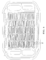
- Figure 6 is similar to Figure 4 except that each channel has fewer medial legs 94 (only one medial leg shown) than in Figure 4, and is particularly useful for handling the cathode (i.e. O 2 ) reactant.
- the Figure 4 configuration utilizing multiple medial legs is particularly useful for handling the anode reactant, hydrogen.
Landscapes
- Life Sciences & Earth Sciences (AREA)
- Engineering & Computer Science (AREA)
- Manufacturing & Machinery (AREA)
- Sustainable Development (AREA)
- Sustainable Energy (AREA)
- Chemical & Material Sciences (AREA)
- Chemical Kinetics & Catalysis (AREA)
- Electrochemistry (AREA)
- General Chemical & Material Sciences (AREA)
- Fuel Cell (AREA)
Abstract
Description
Claims (6)
- In a PEM fuel cell comprising (1) a proton exchange membrane having opposing cathode and anode faces on opposite sides of said membrane, (2) a gas-permeable, electrically conductive cathode current collector engaging said cathode face, (3) a gas-permeable, electrically-conductive anode current collector engaging said anode face, and (4) a current-collecting plate engaging at least one of said gas-permeable cathode and anode current collectors and defining a gas flow field confronting said one gas-permeable collector, said flow field comprising a plurality of lands engaging said one current collector and defining a plurality of substantially equal-length serpentine gas flow channels, the improvement wherein each of said channels comprises (a) a plurality of serially-linked serpentine segments that lie in a first general direction extending between a gas supply manifold and a gas exhaust manifold, said segments each having an inlet leg for receiving gas into the segment at a first pressure, an exit leg for exhausting said gas from said segment at a second pressure less than said first pressure, at least one medial leg intermediate said inlet and exit legs, said inlet, exit and medial legs for each channel at least in part bordering at least one other leg of the same channel, and a reverse turn at each end of said medial leg connecting said medial leg to adjacent legs of the same channel, and (b) a bridging section coupling the exit leg of one segment to the inlet leg of the next adjacent segment downstream of said one segment in the same channel.
- The PEM fuel cell according to claim 1 wherein said segments each include a plurality of said medial legs intermediate said inlet and exit legs.
- The PEM fuel cell according to claim lwherein each channel comprises at least three said serially-linked serpentine segments.
- The PEM fuel cell according to claim 1 wherein said inlet leg lies along a first side of said segment and said exit leg lies along a second side of said segment opposite said first side , and said bridging section extends in a second general direction transverse said first general direction.
- The PEM fuel cell according to claim 4 wherein the end of the medial leg that, in operation, is at a pressure closest to the pressure in said bridging section is spaced from said bridging section by a first distance, and the end of the medial leg that, in operation, is at a pressure farthest from the pressure in said bridging section is spaced from the bridging section by a second distance which is less than said first distance.
- The PEM fuel cell according to claim 1 wherein the cathode current-collecting plate defines a flow field having flow channels that are shorter in length than the flow channels defined by the anode current-collecting plate so as to permit a pressure drop between the supply and exhaust manifolds for the cathode that is substantially the same as the pressure drop between the supply and exhaust manifolds for the anode when the pressure of the anode and cathode reactants supplied to said fuel cell are substantially the same.
Applications Claiming Priority (2)
| Application Number | Priority Date | Filing Date | Title |
|---|---|---|---|
| US459592 | 1999-12-13 | ||
| US09/459,592 US6309773B1 (en) | 1999-12-13 | 1999-12-13 | Serially-linked serpentine flow channels for PEM fuel cell |
Publications (3)
| Publication Number | Publication Date |
|---|---|
| EP1109241A2 true EP1109241A2 (en) | 2001-06-20 |
| EP1109241A3 EP1109241A3 (en) | 2004-10-20 |
| EP1109241B1 EP1109241B1 (en) | 2008-11-26 |
Family
ID=23825412
Family Applications (1)
| Application Number | Title | Priority Date | Filing Date |
|---|---|---|---|
| EP00122709A Expired - Lifetime EP1109241B1 (en) | 1999-12-13 | 2000-10-18 | Flow channels in current collector plates for fuel cells |
Country Status (5)
| Country | Link |
|---|---|
| US (1) | US6309773B1 (en) |
| EP (1) | EP1109241B1 (en) |
| JP (1) | JP3495700B2 (en) |
| CA (1) | CA2323147A1 (en) |
| DE (1) | DE60040897D1 (en) |
Cited By (6)
| Publication number | Priority date | Publication date | Assignee | Title |
|---|---|---|---|---|
| DE10204598A1 (en) * | 2002-02-05 | 2003-08-07 | Volkswagen Ag | Process for improving heat and mass transport in a diffusion layer of a fuel cell and corresponding fuel cell |
| WO2004017449A3 (en) * | 2002-07-19 | 2004-04-29 | Daimlerchrisler Ag | Internally gas regulated fuel cell |
| US6780536B2 (en) | 2001-09-17 | 2004-08-24 | 3M Innovative Properties Company | Flow field |
| WO2006036606A3 (en) * | 2004-09-28 | 2007-07-05 | Honda Motor Co Ltd | Separator plates, ion pumps, and hydrogen fuel infrastructure systems and methods for generating hydrogen |
| DE10394231B4 (en) * | 2003-04-18 | 2009-08-06 | General Motors Corp. (N.D.Ges.D. Staates Delaware), Detroit | Embossed bipolar plate and separator for fuel cells |
| DE10392388B4 (en) * | 2002-03-18 | 2010-08-05 | General Motors Corp., Detroit | Fuel cell with a proton exchange membrane |
Families Citing this family (53)
| Publication number | Priority date | Publication date | Assignee | Title |
|---|---|---|---|---|
| US6503653B2 (en) | 2001-02-23 | 2003-01-07 | General Motors Corporation | Stamped bipolar plate for PEM fuel cell stack |
| US20020172852A1 (en) * | 2001-05-15 | 2002-11-21 | David Frank | Flow field plate for a fuel cell and fuel cell assembly incorporating the flow field plate |
| US6852439B2 (en) * | 2001-05-15 | 2005-02-08 | Hydrogenics Corporation | Apparatus for and method of forming seals in fuel cells and fuel cell stacks |
| US20050095492A1 (en) * | 2001-05-15 | 2005-05-05 | Hydrogenics Corporation | Fuel cell stack |
| US6878477B2 (en) | 2001-05-15 | 2005-04-12 | Hydrogenics Corporation | Fuel cell flow field plate |
| DE10158772C1 (en) * | 2001-11-23 | 2003-06-26 | Reinz Dichtungs Gmbh & Co Kg | The fuel cell system |
| US6998188B2 (en) * | 2002-02-19 | 2006-02-14 | Petillo Phillip J | Fuel cell components |
| US6924052B2 (en) * | 2002-04-24 | 2005-08-02 | General Motors Corporation | Coolant flow field design for fuel cell stacks |
| US7081316B2 (en) * | 2002-04-30 | 2006-07-25 | General Motors Corporation | Bipolar plate assembly having transverse legs |
| US6773841B2 (en) * | 2002-04-25 | 2004-08-10 | General Motors Corporation | Fuel cell having insulated coolant manifold |
| JP4245308B2 (en) * | 2002-05-16 | 2009-03-25 | 株式会社日本自動車部品総合研究所 | Fuel cell |
| US6887610B2 (en) * | 2003-01-21 | 2005-05-03 | General Motors Corporation | Joining of bipolar plates in proton exchange membrane fuel cell stacks |
| AU2003293468A1 (en) * | 2003-01-31 | 2004-08-30 | General Motors Corporation | Flow restrictors in fuel cell flow-field |
| US20040151960A1 (en) * | 2003-01-31 | 2004-08-05 | Rock Jeffrey Allan | Flow restrictors in fuel cell flow-field |
| US20040151971A1 (en) * | 2003-01-31 | 2004-08-05 | Rock Jeffrey Allan | PEM fuel cell with flow-field having a branched midsection |
| US7195836B2 (en) * | 2003-03-07 | 2007-03-27 | General Motors Corporation | Polymeric separator plates |
| US6864004B2 (en) * | 2003-04-03 | 2005-03-08 | The Regents Of The University Of California | Direct methanol fuel cell stack |
| RU2286622C2 (en) * | 2003-04-22 | 2006-10-27 | Джапан Аэроспейс Эксплорэйшн Эйдженси | Fuel cell using licensed solid electrolyte |
| CA2522731C (en) * | 2003-05-16 | 2013-03-19 | Hydrogenics Corporation | Flow field plate for a fuel cell and fuel cell assembly incorporating the flow field plate |
| EP1644997A4 (en) * | 2003-06-27 | 2011-03-16 | Ultracell Corp | Micro fuel cell architecture |
| US20050069749A1 (en) * | 2003-08-15 | 2005-03-31 | David Frank | Flow field plate arrangement |
| US6974648B2 (en) * | 2003-09-12 | 2005-12-13 | General Motors Corporation | Nested bipolar plate for fuel cell and method |
| WO2005028712A1 (en) * | 2003-09-22 | 2005-03-31 | Hydrogenics Corporation | Electrolyzer cell stack system |
| WO2005028714A1 (en) | 2003-09-22 | 2005-03-31 | Hydrogenics Corporation | Apparatus and method for reducing instances of pump de-priming |
| CA2538738A1 (en) * | 2003-09-22 | 2005-03-31 | Hydrogenics Corporation | Electrolyzer cell arrangement |
| US20050095494A1 (en) * | 2003-11-03 | 2005-05-05 | Fuss Robert L. | Variable catalyst loading based on flow field geometry |
| US7214442B2 (en) * | 2003-12-02 | 2007-05-08 | Los Alamos National Security, Llc | High specific power, direct methanol fuel cell stack |
| US8486575B2 (en) * | 2004-02-05 | 2013-07-16 | GM Global Technology Operations LLC | Passive hydrogen vent for a fuel cell |
| US7618734B2 (en) * | 2004-05-19 | 2009-11-17 | General Motors Corporation | Branched fluid channels for improved fluid flow through fuel cell |
| US7531264B2 (en) * | 2004-06-07 | 2009-05-12 | Hyteon Inc. | Fuel cell stack with even distributing gas manifolds |
| US7524575B2 (en) * | 2004-06-07 | 2009-04-28 | Hyteon Inc. | Flow field plate for use in fuel cells |
| US20060008695A1 (en) * | 2004-07-09 | 2006-01-12 | Dingrong Bai | Fuel cell with in-cell humidification |
| KR100563226B1 (en) | 2004-08-10 | 2006-03-21 | 한국생산기술연구원 | Separator for Fuel Cell |
| US7314680B2 (en) * | 2004-09-24 | 2008-01-01 | Hyteon Inc | Integrated fuel cell power module |
| KR100626034B1 (en) * | 2004-11-13 | 2006-09-20 | 삼성에스디아이 주식회사 | Bipolar Plate and Direct Liquid Fuel Cell Stacks |
| KR100647666B1 (en) | 2004-11-29 | 2006-11-23 | 삼성에스디아이 주식회사 | Bipolar Plate and Direct Liquid Fuel Cell Stacks |
| US7348094B2 (en) * | 2004-12-10 | 2008-03-25 | Gm Global Technology Operations, Inc. | Enhanced flowfield plates |
| US7479333B2 (en) | 2004-12-13 | 2009-01-20 | Hyteon, Inc. | Fuel cell stack with multiple groups of cells and flow passes |
| US20060188763A1 (en) * | 2005-02-22 | 2006-08-24 | Dingrong Bai | Fuel cell system comprising modular design features |
| US20060210855A1 (en) * | 2005-03-15 | 2006-09-21 | David Frank | Flow field plate arrangement |
| US20060210857A1 (en) * | 2005-03-15 | 2006-09-21 | David Frank | Electrochemical cell arrangement with improved mea-coolant manifold isolation |
| US7829231B2 (en) * | 2005-04-22 | 2010-11-09 | Gm Global Technology Operations, Inc. | Fuel cell design with an integrated heat exchanger and gas humidification unit |
| KR100722093B1 (en) * | 2005-10-19 | 2007-05-25 | 삼성에스디아이 주식회사 | Membrane electrode assembly for fuel cell, manufacturing method thereof, and fuel cell system employing the same |
| US8455155B2 (en) * | 2006-11-22 | 2013-06-04 | GM Global Technology Operations LLC | Inexpensive approach for coating bipolar plates for PEM fuel cells |
| US20080199752A1 (en) * | 2007-02-20 | 2008-08-21 | Commonwealth Scientific And Industrial Research Organisation | Electrochemical stack with pressed bipolar plate |
| US8227136B2 (en) * | 2008-10-30 | 2012-07-24 | GM Global Technology Operations LLC | Using ionomer to militate against membrane buckling in the tenting region |
| US9921000B2 (en) * | 2011-07-22 | 2018-03-20 | 8 Rivers Capital, Llc | Heat exchanger comprising one or more plate assemblies with a plurality of interconnected channels and related method |
| JP6064049B2 (en) * | 2012-08-30 | 2017-01-18 | アウディ アクチェンゲゼルシャフトAudi Ag | Fuel cell components having a selected cooling capacity distribution |
| DK3792576T3 (en) | 2018-09-04 | 2023-01-09 | Ovh | WATER BLOCK WITH A FLUID LINE |
| DE202018004979U1 (en) * | 2018-10-25 | 2020-01-28 | Reinz-Dichtungs-Gmbh | Plate-like liquid container and battery temperature control arrangement |
| CN113871647B (en) * | 2021-12-07 | 2022-03-01 | 浙江天能氢能源科技有限公司 | Air-cooling integrated membrane electrode structure of fuel cell and preparation method thereof |
| CN114976101B (en) * | 2022-05-26 | 2024-07-05 | 西安交通大学 | One-end sealed ceramic flat tube supported solid oxide fuel cell/electrolyzer and battery stack structure |
| CN117352767B (en) * | 2023-12-04 | 2024-02-23 | 无锡黎曼机器人科技有限公司 | Flexible adjustment mechanism of snakelike runner board and flow cell snakelike runner assembly systems |
Family Cites Families (6)
| Publication number | Priority date | Publication date | Assignee | Title |
|---|---|---|---|---|
| US4988583A (en) | 1989-08-30 | 1991-01-29 | Her Majesty The Queen As Represented By The Minister Of National Defence Of Her Majesty's Canadian Government | Novel fuel cell fluid flow field plate |
| US5863671A (en) | 1994-10-12 | 1999-01-26 | H Power Corporation | Plastic platelet fuel cells employing integrated fluid management |
| US5514487A (en) * | 1994-12-27 | 1996-05-07 | Ballard Power Systems Inc. | Edge manifold assembly for an electrochemical fuel cell stack |
| US6099984A (en) * | 1997-12-15 | 2000-08-08 | General Motors Corporation | Mirrored serpentine flow channels for fuel cell |
| US5945232A (en) * | 1998-04-03 | 1999-08-31 | Plug Power, L.L.C. | PEM-type fuel cell assembly having multiple parallel fuel cell sub-stacks employing shared fluid plate assemblies and shared membrane electrode assemblies |
| JP4542640B2 (en) * | 1999-02-23 | 2010-09-15 | 本田技研工業株式会社 | Fuel cell stack |
-
1999
- 1999-12-13 US US09/459,592 patent/US6309773B1/en not_active Expired - Lifetime
-
2000
- 2000-10-11 CA CA002323147A patent/CA2323147A1/en not_active Abandoned
- 2000-10-18 DE DE60040897T patent/DE60040897D1/en not_active Expired - Lifetime
- 2000-10-18 EP EP00122709A patent/EP1109241B1/en not_active Expired - Lifetime
- 2000-12-13 JP JP2000379014A patent/JP3495700B2/en not_active Expired - Fee Related
Cited By (12)
| Publication number | Priority date | Publication date | Assignee | Title |
|---|---|---|---|---|
| US6780536B2 (en) | 2001-09-17 | 2004-08-24 | 3M Innovative Properties Company | Flow field |
| DE10204598A1 (en) * | 2002-02-05 | 2003-08-07 | Volkswagen Ag | Process for improving heat and mass transport in a diffusion layer of a fuel cell and corresponding fuel cell |
| US7029776B2 (en) | 2002-02-05 | 2006-04-18 | Volkswagon Ag | Method for improving a heat and mass transport in a diffusion layer of a fuel cell, and corresponding fuel cell |
| EP1333516A3 (en) * | 2002-02-05 | 2006-12-13 | Volkswagen Aktiengesellschaft | Fuel cell and process for improving the transport of heat and matter in a diffusion layer of a fuel cell |
| DE10392388B4 (en) * | 2002-03-18 | 2010-08-05 | General Motors Corp., Detroit | Fuel cell with a proton exchange membrane |
| WO2004017449A3 (en) * | 2002-07-19 | 2004-04-29 | Daimlerchrisler Ag | Internally gas regulated fuel cell |
| US7972748B2 (en) | 2002-07-19 | 2011-07-05 | Daimler Ag | Internally gas regulated fuel cell |
| US8039170B2 (en) | 2002-07-19 | 2011-10-18 | Daimler Ag | Internally gas regulated fuel cell |
| DE10394231B4 (en) * | 2003-04-18 | 2009-08-06 | General Motors Corp. (N.D.Ges.D. Staates Delaware), Detroit | Embossed bipolar plate and separator for fuel cells |
| WO2006036606A3 (en) * | 2004-09-28 | 2007-07-05 | Honda Motor Co Ltd | Separator plates, ion pumps, and hydrogen fuel infrastructure systems and methods for generating hydrogen |
| US7686937B2 (en) | 2004-09-28 | 2010-03-30 | Honda Motor Co., Ltd. | Separator plates, ion pumps, and hydrogen fuel infrastructure systems and methods for generating hydrogen |
| US8715470B2 (en) | 2004-09-28 | 2014-05-06 | Honda Motor Co., Ltd. | Separator plates, ion pumps, and hydrogen fuel infrastructure systems and methods for generating hydrogen |
Also Published As
| Publication number | Publication date |
|---|---|
| EP1109241A3 (en) | 2004-10-20 |
| JP3495700B2 (en) | 2004-02-09 |
| EP1109241B1 (en) | 2008-11-26 |
| JP2001176525A (en) | 2001-06-29 |
| CA2323147A1 (en) | 2001-06-13 |
| US6309773B1 (en) | 2001-10-30 |
| DE60040897D1 (en) | 2009-01-08 |
Similar Documents
| Publication | Publication Date | Title |
|---|---|---|
| US6309773B1 (en) | Serially-linked serpentine flow channels for PEM fuel cell | |
| US6699614B2 (en) | Converging/diverging flow channels for fuel cell | |
| US6099984A (en) | Mirrored serpentine flow channels for fuel cell | |
| US6358642B1 (en) | Flow channels for fuel cell | |
| US6893770B2 (en) | Stamped bipolar plate for PEM fuel cell stack | |
| EP1135821B1 (en) | Sheet metal bipolar plate design for polymer electrolyte membrane fuel cells | |
| US7112385B2 (en) | Flow restrictors in fuel cell flow-field | |
| US20050064270A1 (en) | Fuel cell bipolar separator plate | |
| US20040151974A1 (en) | PEM fuel cell with flow-field having a branched midsection | |
| JP4185734B2 (en) | Fuel cell stack | |
| WO2004070859A1 (en) | Pem fuel cell with flow-field having a branched midsection | |
| WO2004070855A2 (en) | Flow restrictors in fuel cell flow-field | |
| JP2006514405A (en) | Flow restrictor in fuel cell flow field |
Legal Events
| Date | Code | Title | Description |
|---|---|---|---|
| PUAI | Public reference made under article 153(3) epc to a published international application that has entered the european phase |
Free format text: ORIGINAL CODE: 0009012 |
|
| AK | Designated contracting states |
Kind code of ref document: A2 Designated state(s): AT BE CH CY DE DK ES FI FR GB GR IE IT LI LU MC NL PT SE |
|
| AX | Request for extension of the european patent |
Free format text: AL;LT;LV;MK;RO;SI |
|
| PUAL | Search report despatched |
Free format text: ORIGINAL CODE: 0009013 |
|
| AK | Designated contracting states |
Kind code of ref document: A3 Designated state(s): AT BE CH CY DE DK ES FI FR GB GR IE IT LI LU MC NL PT SE |
|
| AX | Request for extension of the european patent |
Extension state: AL LT LV MK RO SI |
|
| 17P | Request for examination filed |
Effective date: 20041217 |
|
| 17Q | First examination report despatched |
Effective date: 20050513 |
|
| AKX | Designation fees paid |
Designated state(s): DE |
|
| 17Q | First examination report despatched |
Effective date: 20050513 |
|
| GRAP | Despatch of communication of intention to grant a patent |
Free format text: ORIGINAL CODE: EPIDOSNIGR1 |
|
| GRAS | Grant fee paid |
Free format text: ORIGINAL CODE: EPIDOSNIGR3 |
|
| GRAA | (expected) grant |
Free format text: ORIGINAL CODE: 0009210 |
|
| AK | Designated contracting states |
Kind code of ref document: B1 Designated state(s): DE |
|
| REF | Corresponds to: |
Ref document number: 60040897 Country of ref document: DE Date of ref document: 20090108 Kind code of ref document: P |
|
| PLBE | No opposition filed within time limit |
Free format text: ORIGINAL CODE: 0009261 |
|
| STAA | Information on the status of an ep patent application or granted ep patent |
Free format text: STATUS: NO OPPOSITION FILED WITHIN TIME LIMIT |
|
| 26N | No opposition filed |
Effective date: 20090827 |
|
| PGFP | Annual fee paid to national office [announced via postgrant information from national office to epo] |
Ref country code: DE Payment date: 20191008 Year of fee payment: 20 |
|
| REG | Reference to a national code |
Ref country code: DE Ref legal event code: R071 Ref document number: 60040897 Country of ref document: DE |