BACKGROUND OF THE INVENTION
The present invention relates to a vacuum switch
including vacuum-measurement devices, switchgear using the
vacuum switch, and an operation method thereof.
The break performance and the withstand-voltage
performance of a vacuum switchgear rapidly deteriorate when
the degree of vacuum decreases to below 10-4 Torr. Changes
in the degree of vacuum are caused by leakage-in of gas from
cracks which have chapped, discharge of gas molecules which
have been absorbed in metal and insulation members composing
a vacuum vessel, penetration of ambient gas, etc. As the size
of a vacuum vessel is increased in accordance with an increase
of the applied voltage, it becomes unable to disregard the
penetration of ambient gas into the vacuum vessel. It is well
known that the degree of vacuum in a vacuum circuit-breaker
is monitored by various means. For example, such monitoring
methods or apparatuses are disclosed in USP5,537,858,
USP5,739,419, USP4,163,130, Japanese Utility Model
Application Laid-Open Sho.55-45160, Japanese Patent
Application Laid-Open Sho.56-36818, Japanese Patent
Application Laid-Open Hei.8-306279, etc. In the contacttype
measurement method such as that disclosed in
USP4,163,130, of measuring the degree of vacuum in a vacuum
vessel which is not grounded, in order to elevate the voltage
of a vacuum-measurement device, which is equal to the voltage
of a main circuit, from the ground voltage, a transformer
is necessary, and has not come into practical use yet.
Further, although the non-contact-type vacuum-measurement
methods for a vacuum vessel are devised in
USP5,537,858, Hei.8-306279, etc., a method of measuring
changes in the degree of vacuum in a vacuum vessel with the
required accuracy has not become known yet. In Japanese
Utility Model Application Laid-Open Sho.55-45160, although
it is not described that the vacuum vessel is grounded, the
system in which a vacuum-measurement device attached to a
second vacuum vessel containing a first vacuum vessel is
disclosed. Further, it is described in this Japanese Utility
Model Application Laid-Open, that a vacuum pump beside a
vacuum-measurement device is connected to the second vacuum
vessel. However, since the first vacuum vessel does not
communicate with the second vacuum vessel, the degree of
vacuum in the first vacuum vessel cannot be directly measured.
If a vacuum sensor is separated from a main circuit
by using an insulation member, the size of the vacuum sensor,
including the insulation member, is mostly as large as a
vacuum valve. Further, there is a problem in that since
electrons generated in the sensor, then generate secondary
electrons while colliding with the insulation member, that
is, they cause electron multiplication, and these electrons
further enter the vacuum valve, the insulation
characteristics of the vacuum valve deteriorates. By setting
the potential of a line connected to a power source equal
to that of an outer cylindrical electrode of the vacuum sensor
element, and applying the voltage, divided by a capacitor,
to an inner cylindrical electrode, it is possible to remove
the insulation member, which in turn downsizes the vacuum
sensor. However, the size of a vacuum measurement device
becomes large in the last results because insulation of the
capacitor from the earth is necessary, and the vacuum
measurement device is apt to receive influences of changes
in the voltage of the main circuit (for example, surge
voltage). Further, since the potential of the vacuum sensor
element is equal to that of the line connected to the power
source, an insulation transformer or a light transmission
line is necessary to transmit a signal to a measurement unit,
an alarm lamp, a relay for generating an alarm, etc., and
this makes the measurement system complicated.
SUMMARY OF THE INVENTION
An objective of the present invention is to provide
a vacuum switch and a vacuum switchgear using the vacuum
switch, in which the vacuum switch is downsized, and its
degree of vacuum can be measured and monitored reliably, by
putting a vacuum circuit-breaker and a disconnector into
different grounded vacuum vessels, respectively, by
providing a vacuum measurement device at each grounded
vessel; and its reliability is improved by composing the
vacuum switchgear so that, even if a defect or a malfunction
occurs in the vacuum circuit-breaker and the disconnector,
its effects do not propagate in the whole of the vacuum switch.
To achieve the above objective, the present invention
provides a vacuum switch comprising: grounded vacuum vessels
in which a vacuum circuit-breaker portion and a disconnector
portion are contained respectively; and vacuum-measurement
devices which are attached to the grounded vacuum vessels,
respectively.
In the present invention, the vacuum circuit-breaker
portion includes indispensable components composing this
circuit breaker, that is: movable and fixed electrodes,
conductors supporting these electrodes, and a vessel
containing these components. Further, the disconnector
portion is an apparatus, connected to the circuit-breaker,
for maintaining the circuit-breaker in a disconnection state
when it is required, and it sometimes includes a grounding
switch. Furthermore, it includes a vessel containing these
components.
Further, it is desirable in order to assure the safety
of workers who inspect and maintain loads or a switchgear,
to provide a function for checking or continuously monitoring
the degree of vacuum in an operation unit, at a structure
of a switchgear according to the present invention, in which
a circuit-breaker, a disconnector, and a grounding switch
are integrated in a vacuum vessel. As a vacuum valve including
a vacuum-measurement device, a vacuum valve using an
ionization vacuum gauge, a detector to detect the degree of
vacuum by applying voltage to a small gap provided in a vacuum
vessel to cause discharge in the gap, or a magnetron-type
vacuum-sensing element, are well known. Although all the
above well-known detectors can be used in the present
invention, it is favorable to use an ionization vacuum gauge
or a magnetron-type vacuum-sensing element from the view
point of reliability and accuracy. Also, it is possible to
adopt the composition in which a megger is connected to a
measurement element, although this composition is not
suitable for continuous monitoring of the degree of vacuum.
By using this composition, the degree of vacuum can be
measured without a specific power source.
In the vacuum switch of the present invention, a fixed
electrode and a movable electrode are arranged opposite to
each other in the vacuum vessel from which these electrodes
are insulated with insulation members, and a first vacuum
vessel surrounding this vacuum vessel is provided. Further,
a vacuum-measurement device is attached to the first vacuum
vessel. Further, it is possible that when the degree of vacuum
is measured, a set of coaxial electrodes and a magnetic
field-generation unit surrounding the coaxial electrodes is
attached to the first vacuum vessel which is grounded and
in which the fixed electrode and the movable electrode are
arranged opposite to each other; and when the degree of vacuum
is not measured, the set is detached from the first vacuum
vessel. Furthermore, it is desirable to provide a vacuum pump
at the grounded vacuum vessel in order to recover the degree
of vacuum in this vacuum vessel when the vacuum deteriorates.
In accordance with the vacuum switchgear of the present
invention, since the vacuum-sensing element can be
electrically separated from the main circuit, the
reliability of the function for measuring or monitoring the
degree of vacuum can be improved, and if the degree of vacuum
deteriorates, the vacuum can be recovered by the vacuum pump,
which in turn ensures the safety of the switchgear. Also,
by separating the circuit-breaker portion from the
disconnector portion, it is possible to prevent a malfunction
which has occurred in either the circuit-breaker portion or
the disconnector portion, from propagating in the whole of
the switchgear. Moreover, since the degree of vacuum in the
vacuum vessel containing the circuit-breaker portion can be
directly monitored, the reliability of the circuit-breaker
portion is improved.
Since the pair of the movable and the fixed electrodes
in the circuit-breaker portion is coaxially arranged with
the pair of the movable and the fixed electrodes in the
disconnector portion, even if a large driving force is applied
to these pairs of electrodes in a disconnecting operation,
this driving force can be absorbed or alleviated by those
coaxially arranged components, which in turn can improve the
reliability of the vacuum switch. Further, since the vacuum
vessel is surrounded by the first or second grounded vacuum
vessel, even if a malfunction occurs in the vacuum vessel,
the vacuum vessel can be protected from the malfunction by
the first or second grounded vacuum vessel.
In accordance with the vacuum switch and the operation
method of the switchgear according to the present invention,
by operating the vacuum pump as the occasion arises, or at
will, the degree of vacuum in not only the grounded vacuum
vessels, but also the vacuum vessel containing the vacuum
circuit-breaker, is improved or maintained at a necessary
level, and this can remarkably improve the performances of
the vacuum switch and the vacuum switchgear.
switch and vacuum switchgear using the vacuum switch.
BRIEF DESCRIPTION OF THE DRAWINGS
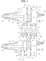
Fig. 1 is a vertical cross section of the composition
of a vacuum switch of an embodiment according to the present
invention.
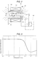
Fig. 2 is a vertical cross section of the structure
of a vacuum-measurement device used for embodiments
according to the present invention.
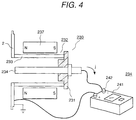
Fig. 3 is a graph indicating the relationship between
the degree of vacuum and the vacuum insulation
characteristics.
Fig. 4 is a schematic diagram of the composition of
a vacuum-measurement device of another embodiment according
to the present invention.
DETAILED DESCRIPTION OF THE EMBODIMENTS
In embodiments of the present invention, a vacuum
switch basically includes a vacuum vessel which contains a
fixed electrode and a movable electrode being connected to,
and disconnected from the fixed electrode, of a circuit-breaker;
a first grounded vacuum vessel which contains the
vacuum vessel, being electrically insulated and
communicating with the vacuum vessel; a second grounded
vacuum vessel which contains a disconnector and a grounding
switch, being electrically insulated from the vacuum vessel
and the first grounded vacuum vessel; an insulation bushing
which is projected from the first grounded vacuum vessel;
a load conductor led out of a bushing projected from the second
grounded vacuum vessel; a grounding conductor led out of
another bushing projected from the second grounded vacuum
vessel; first and second vacuum-measurement devices; a first
operation rod for driving a movable blade for the movable
electrode of the circuit-breaker; and a second operation rod,
which is situated substantially in the direction of the axis
of the first operation rod, for driving a movable blade for
the movable electrode of the disconnector.
In the following, embodiment 1 of the present invention
will be explained with reference to Fig. 1. In this figure,
the vacuum switch includes the vacuum vessel 1 containing
the movable electrode 11 and the fixed electrode 10 of the
circuit-breaker 9; the first grounded vacuum vessel 2
containing the vacuum vessel 1; a vacuum-sensing element 110
attached to the first grounded vacuum vessel 2; a vacuum pump
91 attached to the first grounded vacuum vessel 2; and the
second grounded vacuum vessel containing the disconnector
40 and the grounding switch. Most portions of the vacuum
vessel 1 and the first grounded vacuum vessel 2 are made of
conductive material such as a metal with high strength, for
example, stainless steel. Further, the first grounded vacuum
vessel 2 is grounded. The portions such as member 7 and 8,
other than the conductive portions, are fabricated with
insulation material such as alumina.
The vacuum vessel 1 is composed by locating the
insulation member 7 and 8 on and under the side wall of the
vacuum vessel 1, respectively. The fixed electrode 10 and
the movable electrode 11 which is disconnectable from the
fixed electrode 10, are arranged in the vacuum vessel 1, and
circuit-disconnection or connection is performed by
disconnecting the movable electrode 11 from the fixed
electrode 10, or connecting the movable electrode 11 to the
fixed electrode 10. A movable conductor 15 penetrates the
insulation member 7 connected to the movable electrode 11.
Since there is a narrow gap between the insulation member
7 and the movable conductor 15, which permits the movement
of the movable electrode 11, the vacuum space of the vacuum
vessel 1 communicates with that of the first grounded vacuum
vessel 2. Therefore, the vacuum-sensing element 110 can
directly measure or monitor the degree of vacuum in the vacuum
vessel 1 and the first grounded vacuum vessel 2.
Another terminal of the movable conductor 15 is
connected to a power source conductor 61 via a flexible
conductor 60. This terminal of the movable conductor 15 is
also connected to a link mechanism of an operation unit via
a movable blade 13. The movable blade 13 is hermetically
sealed by a bellows 17.
The first grounded vacuum vessel 2 is composed of an
end plate 20 and a side wall 29, and the vacuum vessel 1 is
surrounded by a vacuum space 2a. A connection part 81 is
connected to a bus bar (not shown in Fig. 1).
At the side of the fixed electrode 10, there is the
second grounded vacuum vessel 3 which contains a movable
electrode 49 and a fixed electrode 50 of the disconnector
40, a flexible conductor 74, and movable and fixed electrodes
31 and 32 of a grounding switch. The first grounded vacuum
vessel 2 is hermetically separated from an insulation member
8. Accordingly, a vacuum-sensing element 120 and a vacuum
pump 90 are attached to the second grounded vacuum vessel
3, independent of the vacuum-sensing element 110 and the
vacuum pump 91. A movable conductor 45 connected to the
movable electrode 49 of the disconnector 40 is connected to
a link mechanism of an operation unit via an insulation member
43 and a connection member 44.
The flexible conductor 74 is electrically connected
to the connection part 82 via the load conductor 70.
Fig. 2 shows a vertical cross section of a
magnetron-type vacuum-measurement device, which is an
example of a vacuum-measurement device used for the
embodiments of the present invention, and a vacuum-sensing
element 150 of this measurement device is attached to the
side wall of the first grounded vacuum vessel 2. The
vacuum-sensing element 150 is composed of a pair of coaxial
electrodes 152 and a coil 156, located surrounding the coaxial
electrodes 152, for generating a magnetic flux. The coaxial
electrodes 152 consist of an outer cylindrical electrode 153
and an inner electrode 153 which is led inside the outer
cylindrical electrode 153, and these electrodes are
electrically insulated from each other. Meanwhile, it is
possible to use a ring permanent magnet in place of the coil
156. Further, even if the direction of N and S polarities
is reversed, the same performance of the vacuum-sensing
element can be obtained.
Next, the operation of the vacuum-sensing element 150
is explained below. The negative DC voltage is applied to
the inner electrode 154 by a power source circuit 130. The
AC voltage or the pulse voltage can also be used. Electrons
emitted from the inner electrode 154 receive Lorentz force
caused by the electric field E and the magnetic field B
generated by the coil 156, and slew around the inner electrode
154. The slewing electrons collide with gas remaining in the
vacuum vessel at which the element 150 is installed, and
ionize this gas. Further, the generated positive ions I move
to the inner electrode 154. Since this ion current j depends
on the quantity of the remaining gas, that is, the pressure
of this gas, this gas pressure can be measured by measuring
the voltage between both terminals of a resistor R. Continuous
monitoring of this gas pressure can be implemented by lighting
an alarm lamp or generating an alarm, which are performed
with a relay operated by the voltage V generated between both
terminals of the resistor R. Here, as shown in Fig. 3, the
disconnection and insulation characteristics of the
circuit-breaker 9 in the vacuum vessel 1 rapidly deteriorate
if the gas pressure P is more than 10-4 Torr, it is necessary
to monitor the degree of vacuum in the vacuum vessel so as
to prevent the degree of vacuum from decreasing to below that
value (the gas pressure from increasing to over that value.)
Since the above-described magnetron-type vacuum-sensing
element 150 can detect about the pressure of 10-6 Torr, it
is effective enough to monitor the degree of vacuum in the
vacuum vessel.
Further, since the vacuum-sensing element 150 is
attached to the grounded vacuum vessel 2, a power source
circuit 140 of the vacuum-sensing element 150 can be separated
from the main circuit of the vacuum switchgear. Accordingly,
a device for isolating the vacuum-sensing element 150, for
example, a transformer, is not necessary, and this makes it
possible to directly connect the resistor R to a measurement
circuit or a relay circuit. Thus, it has become possible to
downsize and simplify the measurement system, which in turn
can reduce the size of the vacuum switch. Furthermore, since
an erroneous operation of the vacuum-sensing element 150 due
to a surge voltage signal from the main circuit 130 does not
occur, the reliability of the sensing element 150 can be
improved. Moreover, since the vacuum-sensing element 150 is
directly attached to the grounded metal vacuum vessel 2, the
number of electrons which enter the vacuum vessel 1 is less
than that in the case where the sensing element 150 is attached
to the vessel 2 via an insulation cylinder, and this can
prevent the insulation and shielding characteristics of the
vacuum vessel 1 from deteriorating.
In addition, since the vacuum pumps 91 and 90 are
attached to the grounded vacuum vessels 2 and 3, respectively,
even in the unlikely event that the degree of vacuum in the
vacuum vessel 1, and the first and second grounded vacuum
vessels 2 or 3 deteriorates due to gas discharge from the
components in these vacuum vessels, it can be detected by
the vacuum- sensing element 110 or 120, for which the above
vacuum-sensing element 150 is adopted, and the degree of
vacuum can be recovered by operating the vacuum pump 91 or
90.
The cylindrical side wall la of the vacuum vessel 1
is made of conductive material such as stainless steel, and
is fixed on the insulation member 8 made of insulation
material such as ceramics. Further, the side wall la is
supported by the insulation member 7. A conductor 14
penetrates the central region of the insulation member 8,
and the fixed electrode 10 is connected to the end of the
conductor 14 in the vacuum vessel 1. The movable electrode
11 is situated opposite to the fixed electrode 10, and these
electrodes compose the circuit-breaker 9. The movable
conductor 15 for driving the movable electrode 11 of the
circuit-breaker 9 in the vacuum vessel 1, is connected to
the flexible conductor 60, and to the movable blade 13 via
the insulation member 12. The movable blade 13 is connected
to an operation mechanism in an operation unit, and it drives
the movable conductor 15 to reciprocate in accordance with
the operation of the operation mechanism. A control device
(not shown in the figures) is situated in the operation
mechanism, and it generates a signal to operate the
circuit-breaker 9. The connection or disconnection between
the movable electrode 11 and the fixed electrode 10 is
implemented by the reciprocation of the movable conductor
15, which is started by this signal.
In this way, since the vacuum vessel 1 is contained
in the first grounded vacuum vessel 2, the potential of the
vacuum vessel 1 is at an intermediate level between the ground
level and the voltage of the main circuit, and this can prevent
the insulation breakdown which may occur between the vacuum
vessel 1 and the first grounded vacuum vessel 2. Further,
since the insulation between the vacuum vessel 1 and the first
grounded vacuum vessel 2 is maintained, even in the unlikely
event that leakage occurs in the vacuum vessel 1, insulation
can sill be maintained.
The first grounded vacuum vessel 2 containing the
vacuum vessel 1 is arranged coaxial with the vacuum vessel
1. An end plate 20 of a convex shape in the inside and down
direction of the vacuum vessel 2, is welded to the end portion
of the vacuum vessel 2. Also, the vacuum-sensing element 120
for sensing the degree of vacuum in the second grounded vacuum
vessel 3 is attached to the second grounded vacuum vessel.
Further, the vacuum pump 90 is attached to the side wall of
this vacuum vessel 3, and it is possible to recover the vacuum
state by using the vacuum pump 90.
Both end sides of the bellows 17 are connected to the
end plate 20 and to an end side of the insulation member 12,
respectively, by which the airtight seal of the first grounded
vacuum vessel 2 is maintained. Further, an end side of the
flexible conductor 60 is fixed to a conductor 61. The side
wall 39 of the second grounded vacuum vessel 3 is made of
conductive material with high strength, for example,
stainless steel. The second grounded vacuum vessel 3 is
arranged coaxial with the first grounded vacuum vessel 2.
The conductor 14 penetrates the insulation member 8, and is
connected to the side wall 39 via the insulation member 8.
Further, the fixed electrode 50 of the disconnector 40 is
situated on the end side of the conductor 14 in the second
grounded vacuum vessel 3. The movable electrode 49 is arranged
opposite to the fixed electrode 50. The movable blade or
conductor 44 is connected to the movable electrode 49 via
the movable conductor 45, the attachment part of the flexible
conductor 74, and the insulation member 43. Both end sides
of a bellows 46 are connected to an end plate 20 and to an
end side of the insulation member 43, respectively, by which
the airtight seal of the second grounded vacuum vessel 3 is
maintained.
The movable blade 44 is connected to an operation case
containing an operation unit, via a link mechanism, and the
operation unit drives the movable blade 44 to reciprocate.
The connection or disconnection between the movable
electrode 49 and the fixed electrode 50 is implemented by
the reciprocation of the movable blade 44. By closing the
circuit-breaker 9 after the disconnector 40 is closed by
slowly applying force to the disconnector 40, it is possible
to approximately balance the force applied to the movable
electrode 11 of the circuit-breaker 9 and the force applied
to the movable electrode 49 of the disconnector 40.
Accordingly, the thickness of the insulation member 8 can
be reduced, and its size can also be decreased.
Moreover, in the grounding switch, the movable
electrode 32 is arranged opposite to the fixed electrode 31.
The movable electrode 32 is connected to the movable blade
or conductor 33. A bellows 34 is provided in the cylinder
formed by the side wall 39. One end side of this bellows 34
is connected to the cylinder, and the other end side of the
bellows 34 is connected to the movable electrode 32 via an
insulation member, by which the airtight seal of the vessel
3 can be maintained. A grounding conductor (not shown in the
figures) is connected to the movable blade 33, and this
conductor is grounded. Also, the movable blade 33 is connected
to a link (not shown in the figures), and the link is further
connected to an operation unit (not shown in the Figures).
The fixed electrode 31 is connected to end sides of a conductor
70 and the flexible conductor 74. The insulation member 43
is connected to the movable conductor 45 via another end side
of the flexible conductor 74. Further, the end side of the
flexible conductor 74 is connected to the conductor 70. The
bushing 71 is provided surrounding the conductor 70.
Furthermore, a load conductor is connected to the main circuit
of the switchgear through an insulation part 82 situated
outside the bushing 71.
The vacuum-sensing element 120 is attached to the side
wall 39 of the second grounded vacuum vessel 3.
Since the vacuum switch is composed so that the first
and second grounded vacuum vessels 2 and 3 are serially
arranged in a line, it has become possible to provide a compact
switchgear of small width. Moreover, since the respective
first and second grounded vacuum vessels 2 and 3 are grounded,
and the potential of their side walls is equal to the ground
potential, the respective switches for three phases can
contact each other, or they can be laid near each other, which
in turn makes it possible to provide a compact switchgear.
The movable blade 13 is connected to the drive mechanism
for driving this blade to reciprocate, and the fixed
electrodes 10 and 50 of the circuit-breaker 9 and the
disconnector 40 are connected to both end sides of the fixed
conductor 14, respectively. Therefore, it is possible to
balance the force applied to the movable electrode 11 of the
circuit-breaker 9 and that of the disconnector 40, and this
can reduce the thickness of the insulation member 8, and the
size of the vacuum switch. Also, since the vacuum switch is
composed so that the first grounded vacuum vessel 2 containing
the circuit-breaker 9 is connected to the second grounded
vacuum vessel 3 containing the disconnector 40 and the
grounding switch, the reliability in the insulation
characteristics of the vacuum switch can be improved.
Moreover, since the circuit-breaker 9, the disconnector 40,
and the grounding switch can be separately fabricated, the
freedom in composing the switchgear is increased.
The spaces inside the respective vacuum-sensing
elements 110 and 120 communicate with the spaces inside the
respective first and second grounded vacuum vessels 2 and
3, and the degree of vacuum in these spaces is continuously
measured or monitored. Since the vacuum pumps 90 and 91 are
attached to the respective first and second grounded vacuum
vessels 2 and 3, even in the unlikely event that the degree
of vacuum deteriorates due to discharge of gas from parts
composing the vacuum switch, it is possible to recover the
degree of vacuum in these vessels by detecting the
deterioration of the degree of vacuum with the vacuum-sensing
elements 110 and 120, and operating the pumps 90 and 91. In
this way, the safety and reliability of the vacuum switch
can be improved. Thus, the present invention has remarkable
advantages of monitoring the degree of vacuum in the vacuum
switch and improving the performance of the vacuum switch.
In a vacuum switch, it is favorable to install a
vacuum-measurement device outside a vacuum vessel containing
a fixed electrode and a movable electrode of a circuit-breaker
in order to prevent metal particles which are emitted from
the electrodes when the electrodes are disconnected, from
entering the vacuum-measurement device. Further, by using
magnetic material for the attachment member of the
vacuum-measurement device, the magnetic reluctance of the
vacuum-measurement device can be decreased.
As an example of a vacuum-sensing element for the
vacuum-measurement device, a vacuum-sensing element which
includes coaxial electrodes and a magnetic field-generating
element, for sensing the degree of vacuum, can be used.
Further, it is possible to provide an electrode whose
potential is set equal to an external electrode, which is
located opposite to the inner central electrode of the above
vacuum-sensing element. In the concept of the present
invention, there can be various modifications or
improvements such as that indicated by the above coaxial
electrode composed of a cup-type ceramic cylinder whose
inside surface is plated with metal, and the inner central
electrode penetrating the base of the ceramic cylinder.
Furthermore, a megger can be used as the power source
of the vacuum-sensing element. Fig. 4 shows a schematic
diagram of the composition of the vacuum-measurement device
to which a megger is used for a power source. The
vacuum-sensing element of the vacuum-measurement device 230
is attached to the grounded vacuum vessel 2. The vacuum-sensing
element includes the inner electrode 233 and the outer
electrode 234 located surrounding the electrode 233, and both
electrodes are insulated from each other by the insulation
member 231. A pair of permanent magnets 237 are arranged
outside the outer electrodes 233. When measuring the degree
of vacuum, the measurement is carried out by connecting the
terminal of the megger 243 to the inner electrode 234 and
the vacuum vessel 2, wherein the megger is used as the power
source. In this embodiment, since an independent power source
is not necessary, the measurement device can be simplified,
and is safe.
As described above, in accordance with the present
invention, it has become possible to improve the reliability
of measuring and monitoring the degree of vacuum in a vacuum
switch, and consequently to provide a highly safe vacuum
switch and switchgear.