EP1109135A2 - Image processing method and image processing apparatus using the same - Google Patents
Image processing method and image processing apparatus using the same Download PDFInfo
- Publication number
- EP1109135A2 EP1109135A2 EP00311033A EP00311033A EP1109135A2 EP 1109135 A2 EP1109135 A2 EP 1109135A2 EP 00311033 A EP00311033 A EP 00311033A EP 00311033 A EP00311033 A EP 00311033A EP 1109135 A2 EP1109135 A2 EP 1109135A2
- Authority
- EP
- European Patent Office
- Prior art keywords
- texels
- texture
- filtering domain
- filtering
- image processing
- Prior art date
- Legal status (The legal status is an assumption and is not a legal conclusion. Google has not performed a legal analysis and makes no representation as to the accuracy of the status listed.)
- Withdrawn
Links
Images



Classifications
-
- G—PHYSICS
- G06—COMPUTING OR CALCULATING; COUNTING
- G06T—IMAGE DATA PROCESSING OR GENERATION, IN GENERAL
- G06T15/00—Three-dimensional [3D] image rendering
- G06T15/04—Texture mapping
Definitions
- the present invention relates generally to an image processing method and an image processing apparatus using the same, and, more particularly, to a method for acquiring texture color taking into consideration LOD (Level of Detail) values of object data such as polygon data, as well as to an image processing apparatus using the same.
- LOD Level of Detail
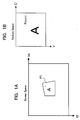
- Fig. 1 depicts texture mapping in computer graphics technology.
- Fig. 1A shows screen space in (sx, sy) coordinate system, in which a texture suitable for the polygon PG performed as an object on the screen is read from texture memory and mapped per pixel.
- point x of a polygon PG indicates one of the pixels which compose a polygon PG in (sx, sy) coordinate system.
- Fig. 1B shows texture space in (u, v) coordinate system of texture memory. There texture appropriate for each pixel is read by accessing the address space in texture memory included in the polygon data.
- point X is a texel in address space (tu, tv) in texture memory, equivalent to the point x of polygon PG on the screen.
- texture color of the texel which is determined by address space (tu, tv) of texture memory is to be mapped onto the polygon as it is, it would be difficult to get a smooth rendering image when polygon moves in the direction parallel to the screen, as the degree of the texture color variance is large.
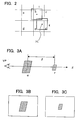
- Fig. 2 depicts the bilinear filtering.
- texels a to f in texture memory are shown.
- texture address of the pixel corresponding to texel b switches to that of texel e.
- the simple transition from texel b to texel e causes nonsmooth image rendering, as color variance is too large.
- weighted averaging is needed for a pixel and adjacent four texels, i.e., weighted averaging is to be made in domain II of the 1 x 1 texel which includes the centered pixel PC and adjacent texels b, c, e, and f.
- the calculation result should be the color value of the texture to be obtained.
- Fig. 3 depicts the relation between the distance from a viewpoint (VP) and the rendering image of polygons. As is indicated in Fig. 3A., such a case should be studied when polygons move vertically against the VP.
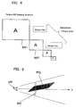
- texture MIP mapping structure as shown in Fig. 4 is employed.
- the MIP map which best matches the polygon is selected according to the distance from VP, namely, the LOD level.
- the domain ⁇ is to be put in-between, and the texture color, whose value is calculated from those of the texture colors of MP1 and MP2 is to be interpolated.
- Texture color values for MP1 and MP2 are obtained from that of bilinearly filtered texture color, explained in Fig. 2.
- bilinear filtering and trilinear filtering techniques are known as smoothening technique of image rendering.
- the LOD value of the texture to be mapped onto polygon PG becomes larger in proportion to the Z value of the pixel.
- texture is to be given as MIP map structure to avoid the large color variance, aliasing, at the time of texture mapping to polygon.
- texture MIP map corresponding to the LOD value of the polygon should be referred to.
- Trilinear filtering technique With bilinear filtering technique, a discontinuity in the texture will remain at the point of the transition of texture MIP maps chosen according to the LOD values. Trilinear filtering technique is used to avoid this defect .
- a color value to be interpolated is calculated from two texture color values of the neighboring texture MIP maps bilinearly filtered according to the LOD values.
- the discontinuity in the texture can be adjusted by adopting the calculation result (interpolation) as the ultimate texture color.
- Trilinear filtering is so composed as to generate the texture color from two texture maps each of which has different LOD; thus unnecessary color information at low frequency will be added.
- the image after filtering becomes blurred by this.
- the size of the domain in which weighted averaging is implemented for a pixel and adjacent texels remains the same in bilinear filtering.
- the additional unnecessary color information of the texel may be added.
- the texture image will be blurred after the filtering procedure.
- the present invention may provide an image processing method capable of obtaining good filtering results with little blurring irrespective of a polygon which is formed so as to be inclined in a z-axial direction and to be prolonged in its inclination direction; and an image processing apparatus using the same.
- the basic concept of an image processing method and an image processing apparatus using the same lies in that a filtering domain is transformed to have an appropriate size by use of at least longitudinal and lateral two-dimensional LOD values with respect to a screen.
- a filtering domain is transformed to have an appropriate size by use of at least longitudinal and lateral two-dimensional LOD values with respect to a screen.
- an image processing method comprising the steps of: operating on a pixel-by-pixel basis texture coordinates and LOD (Level of Detail) values from object data; determining based on the LOD values a filtering domain of texels read from a texture memory; and acquiring a weighted average depending on the texture coordinates and the size of the determined filtering domain to create a texture color to be pasted to the object.
- LOD Level of Detail
- the texel read from the texture memory is determined based on the operated texture coordinates and LOD values.
- determination of the texel filtering domain is performed by use of two or more dimensional LOD values.
- an offset value is added with a predetermined preset parameter to modify the LOD values.
- one of the plurality of mipmap data stored in the texture memory is selected.
- the number of texels required to acquire a texture color is determined in accordance with a predetermined flag.
- the LODs are unified to any one in compliance with the parameter for designating the manner of selecting the plurality of mipmap data.
- the step of acquiring the weighted average includes acquiring a blend ratio and a decision flag in the filtering domain from the texture coordinates and the filtering domain; deciding, by the decision flag, texels to be excluded from the object for acquiring the weighted average, out of the texels read from the texture memory; and acquiring the weighted average of the texels as the object in accordance with the blend ratio.
- the step of determining the filtering domain further includes modifying the LOD values with a predetermined parameter and determining a final filtering domain based on a flag indicative of how many texels are to be used to acquire a texture color; and in case of selecting a mode of four texels by the flag indicative of how many texels are to be used to acquire a texture color, setting the decision flag corresponding to which one of four-divided domains of a texel positioned centrally of nine texels contains the center point of the filtering domain.
- the step of determining the filtering domain further includes modifying the LOD values with a predetermined parameter, and determining a final filtering domain based on a flag indicative of how many texels are to be used to acquire the texture color; and in case of selecting a mode of nine texels by the flag indicative of how many texels are to be used to acquire the texture color, indicating the blend ratio and decision flag correspondingly to four areas into which the nine texels are divided by lines passing through the center of the filtering domain, a first one of the four areas containing the upper left vertex of the filtering domain, a second one of the four areas containing the upper right vertex of the filtering domain, a third one of the four areas containing the lower left vertex of the filtering domain, and a fourth one of the four areas containing the lower right vertex of the filtering domain.
- Fig. 6 is a structural example block diagram of an image displaying apparatus by generic computer graphics to which the present invention is applied.
- a program for processing an image is controlled by a CPU 1.
- the program, or data, and a display list for use in the CPU 1 is stored in a work memory 2.
- polygon data (hereinafter referred to as merely polygon data) as three-dimensional object data of world coordinates, shown as one example in Fig. 7, are read out of the work memory 2 to be input, under control of the CPU 1.
- a perspective transformation is performed to data of a view point coordinates system in which a view point is the origin.
- the polygon data processed in the geometry arithmetic block 3 are led to a renderer 4.
- data on a polygon-by-polygon basis are transformed to data on a pixel-by-pixel basis.
- the data on a pixel-by-pixel basis are next input to a texture forming block 5, and here based on texture data to be stored in a texture RAM 6, a texture color on a pixel-by-pixel is formed.
- a shader block 7 shades the polygon to which the texture color formed by the texture forming block 5 is pasted according to a normal line vector, etc. on a pixel-by-pixel basis.
- a display circuit 8 writes image data from the shader block 7 into a frame buffer 9, or repeatedly controls a readout and executes control of displaying images on a monitor (not shown).
- the present invention is realized and parts having characteristic are in particular the renderer 4 and texture forming block 5.
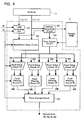
- Fig. 9 is a block diagram showing an embodiment configuration of a staple part of the renderer 4 and texture forming block 5 to be realized according to the present invention.
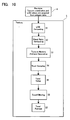
- Fig. 10 is an operating flowchart shown centering operations of the texture forming block 5 in response to Fig. 9.
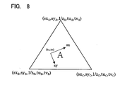
- the renderer 4 inputs three-dimensional coordinates polygon data (Fig. 8) which are perspective-transformed with a view point as the origin from polygon data (Fig. 7) of world coordinates in the geometry arithmetic block 3.
- the polygon data have the three-dimensional coordinates, texture coordinates, normal line vector, etc. in each of vertexes A, B, C of a polygon as vertex data as shown in Fig. 7.
- vertex data As an example of vertex data, the respective three-dimensional coordinates (x A to c, y A to c' z A to c ) and texture coordinates (tu A to c' tv A to c ) are shown, in particular, in relation to the present invention at the vertexes A, B, C.
- these vertex data are sequentially interpolated to operate texture coordinates (tu, tv) of a polygon on a pixel-by-pixel basis. Furthermore, detail LOD values of the polygon are acquired in u and v directions.
- the detail LOD values (lu, lv) of the polygon in the u and v directions are acquired as follows:
- (sx, sy) are screen coordinates.
- a pixel of the screen coordinates is shown so as to correspond to the texture coordinates (tu, tv) in texture coordinates system (u, v)
- a differential amount (lu) in the u direction and a differential amount (lv) in the v direction of the texture coordinates (tu, tv) are detail LOD values (lu, lv) to be acquired. Namely, a differential amount of the texture coordinates with respect to screen coordinates (sx, sy) is acquired.
- Fig. 11B represents the differential amount lu in the u direction of the texture coordinates (tu, tv) with the amount of differential ⁇ (tu)/ ⁇ sx in an sx direction on the screen coordinates and with the amount of differential ⁇ (tu)/ ⁇ sy in an sy direction.
- the differential amount lv in the v direction of the texture coordinates (tu, tv) is represented, as shown in Fig. 11C, with the amount of differential ⁇ (tv)/ ⁇ sx in an sx direction of the screen coordinates, and with the amount of differential ⁇ (tv)/ ⁇ sy in an sy direction.
- a larger one of ⁇ (tu)/ ⁇ sx, ⁇ (tu)/ ⁇ sy ⁇ is selected as the differential amount lu in the u direction of the texture coordinates (tu, tv).
- a mipmap is structured by the size of the second power, it is represented by log 2 , to be set as detail LOD values (lu, lv). In this connection, on the contrary as the embodiment, it is possible to set so as to select a smaller one.
- the detail LOD values (lu, lv) are input into a LOD computing unit 501 of the texture forming block 5, and are fine regulated therein by parameters specified by a user.
- a user has in advance set them in header information of a texture, thereby fine regulating the detail LOD values (step S1).
- the user parameters (up) in which a user intends to fine regulate are input into the LOD computing unit 501.
- the parameters to be input for example, the following parameters exist. lod_offset:
- a filtering domain (dlu, dlv) changes by a method of this mode selection.
- the mipmap selection by the LOD values (lu, lv) will be described in Fig. 12.
- a size of the mipmap is reduced at the second power. Accordingly, as described previously, the LOD values (lu, lv) are represented by log 2 .
- digits 2, 0 at a first place of lu denote mipmaps 2, 0 of Fig. 12, respectively.
- digits 15, 27 of a radix point or less denote the size of a filtering domain in the corresponding mipmap.
- LOD values (lu, lv) are modified in a LOD computing unit 501 by use of the parameters explained above. Furthermore, filtering_mode parameters (fm) are input into the LOD computing unit 501.
- This parameter is a flag for determining by use of how many texels a texture color (tr, tg, tb, ta: including RBG and ⁇ values of transparency, etc.) is acquired, and the following selection can be made:
- a final filtering domain (dlu, dlv) is determined in response to each mode.
- a number of the mipmap selected by an integral of (lu, lv) is designated, and a value in which 1.0 is added up to a fraction becomes a filtering domain.
- an output of the LOD computing unit 501 is input to a blend ratio setup circuit 502.
- a blend ratio for making a weighted average of the texel is acquired (step S2).
- the texels except the domain are decided from a center of the filtering domain and the size of the filtering domain and are excepted from an object of the weighted average.
- the texture coordinates (tu, tv) are at a center PC, and a domain containing texels a to d is a filtering domain X. It is not a square in response to the size of the filtering domain (dlu, dlv).
- the texture coordinates (tu, tv) are at a center PC, and a domain containing texels b, d is a filtering domain X, and the texels a, c are except the filtering domain in the case of acquiring the texture color.
- the texture coordinates (tu, tv) are at a center PC, and a domain containing texels a to i is the filtering domain X. It is not a square in response to the filtering domain (dlu, dlv), here too.
- the texture coordinates (tu, tv) are at a center PC, and a domain containing texels b, c, e, f, h, i is the filtering domain X, and the texels a, d, g are except the filtering domain in the case of acquiring the texture color.
- An output of the blend ratio setup circuit 502 comprises decision flags (cu0, cv0) to (cul, cvl) and blend ratios (bu0, bv0) to (bu1, bv1).
- decision flags (cu0, cv0) to (cu1, cv1) are ones indicating a state of each one bit
- blend ratios (bu0, bv0) to (bu1, bv1) are each a 8-bit value (256 gradations).
- Fig. 17A As shown in Fig. 17A, four texels out of nine texels containing a texel e in which a center of the filtering domain X (a domain enclosed with a broken line in Fig. 17A) exists are read out of a texture RAM 6.
- a method for selecting the decision flags (cu0, cv0) to (cu1, cv1) is different according to at which position the center of the filtering domain exits within the texel e.
- the filtering domain is entered into the four texels of the texels a, b, d, e. For this reason, referring to the flag of (cu0, cv0), the texel for use in the filtering domain is decided.
- the decision flag (cu0, cv0) is indicated as (1,1). Furthermore, in the case where the vertex V exists in the texel b, indicated as (0, 1), and in the case where the vertex V exists in the texel d, indicated as (1, 0), and further in the case where the vertex V exists in the texel e, indicated as (0, 0).
- the decision flag (cu1, cv0) is indicated as (1, 1), and in the case where the vertex V exists in the texel b, indicated as (0, 1), and in the case where the vertex V exists in the texel f, indicated as (1, 0), and in the case where the vertex V exists in the texel e, indicated as (0, 0).
- the decision flag (cu0, cv1) is indicated as (1, 1), and in the case where the vertex V exists in the texel h, indicated as (0, 1), and in the case where the vertex V exists in the texel d, indicated as (1, 0), and in the case where the vertex V exists in the texel e, indicated as (0, 0).
- the decision flag (cu1, cv1) is indicated as (1, 1), and in the case where the vertex V exists in the texel h, indicated as (0, 1), and in the case where the vertex V exists in the texel f, indicated as (1, 0), and in the case where the vertex V exists in the texel e, indicated as (0, 0).
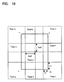
- the blend ratio (bu0, bv0) and the decision flag (cu0, cv0) are shown corresponding to a left-up domain of the filtering domain X containing an vertex A.
- the blend ratio (bu1, bv0) and the decision flag (cu1, cv0) are shown corresponding to a right-up domain of the filtering domain X containing an vertex B
- the blend ratio (bu0, bvl) and the decision flag (cu0, cv1) are shown corresponding to a left-down domain of the filtering domain X containing an vertex C
- the blend ratio (bu1, bv1) and the decision flag (cu1, cv1) are shown corresponding to a right-down domain of the filtering domain X containing an vertex D.
- a method for using each decision flag is same with the case of the case 2 described previously based on Fig. 17.
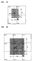
- Fig. 19 is a diagram for explaining a method for acquiring the blend ratio at the time of four-texel sampling.
- Fig. 20 a method for acquiring the blend ratio at the time of 9-texel sampling will be described in Fig. 20.
- (dtu, dtv) is a fraction of the texture coordinates (tu, tv). (bu0, bv0) is shown as follows:
- the texture coordinates (tu, tv) out of outputs of the renderer 4 are input into an address generating circuit 503. Furthermore, the LOD values fine regulated are input from the LOD computing unit 501.
- a real address of the texture RAM 6 is formed (step S3).
- the real address of the texture RAM 6 formed thereby is fed to the texture RAM 6, and it is possible to access in order to read out the nine corresponding texels centering the texture coordinates (tu, tv).
- the address formed by the address generating circuit 503 is fed to a texel sample circuit 504.
- the texels one sample in the case 1, four samples in the case 2, and nine texel samples in the case 3) in a predetermined range corresponding to the cases 1 to 3 centering the address read out of the texel sample circuit 504 and texture RAM 6 are obtained (step S4).
- an output (the blend ratio and decision flag) from the blend ratio setup circuit 502 and an output of the texel sample circuit 504 are input into four sets of texel setup circuit 505(1) to 505(4).
- a setup of the texels is carried out (step S5).
- the texel setup circuits 505(1) to 505(4) are constituted by selector circuits, and the texel setup circuits 505(1) to 505(4) receive the blend ratios (bu0, bv0) to (bu1, bv1) and the decision flags (cu0, cv0) to (cu1, cv1) from the blend ratio setup circuit 502, and receive 1 to 9 texels from the texel sample circuit 504. At this point of time, the texels are arranged in order stored in a memory.
- the texels are rearranged to 1, 4, 9 texels in response to the above filtering_mode. Namely, in the case where filtering_mode is the case 2, as shown in Figs. 13 and 14, four texels are arranged. In the case where filtering_mode is the case 3, as shown in Figs. 15 and 16, nine texels are arranged.
- the unnecessary texels are excluded based on the decision flags (cu0, cv0) to (cu1, cv1). Namely, in the example of Fig. 14, the texel a and texel c are excluded. In the example of Fig. 16, the texel a, texel d, and texel g are excluded.
- the four sets of texel filtering circuits 506(1) to 506(4) acquire a weighted average of the four texels, respectively (step S6).
- the texel filtering circuits 506(1) to 506(4) can be structured by interpolators.
- the texel filtering circuit 506 may be one.
- the blend ratio (bu0, bv0) and the texels a to d are input from the texel setup circuit 505(1) to the texel filtering circuit 506(1).
- the texel filtering circuit 506(1) acquires a weighted average value of the texels a to d in accordance with the blend ratio (bu0, bv0) to be output.
- filtering_mode is the case 3
- the texture color is formed from the nine texels.
- a division is made into four domains, and the respective weighted average values are acquired by the texel filtering circuits 506(1) to 506(4).
- the blend ratio (bu0, bv0) and the texels a, b, d, e are input into the texel filtering circuit 506(1), in order to acquire weighted average values of the four texels a, b, d, e in accordance with the blend ratio (bu0, bv0).
- the blend ratio (bu1, bv0) and the texels b, c, e, f are input into the texel filtering circuit 506(2), in order to acquire weighted average values of the four texels b, c, e, f in accordance with the blend ratio (bu1, bv0).
- the blend ratio (bu0, bv1) and the texels d, e, g, h are input into the texel filtering circuit 506(3), in order to acquire weighted average values of the four texels d, e, g, h in accordance with the blend ratio (bu0, bv1).
- the texel filtering circuit 506(4) acquires weighted average values of the four texels e, f, h, i in accordance with the blend ratio (bu1, bv1).
- a texel average circuit 507 receives four weighted average values output from the texel filtering circuits 506(1) to 506(4).
- the weighted average values of the texel filtering circuit 506(1) are output as texture colors (tr, tg, tb, ta) composed of ⁇ components representing RGB components, transparency, or the like.
- filtering_mode receives the four weighted average values of the texel filtering circuits 506(1) to 506(4).
- the four values are averaged to output the value as the texture colors (tr, tg, tb, ta).
- this is not a structure of processing the texture colors from two texture maps of a different LOD level unlike a trilinear filtering in the conventional method. Accordingly, color information of low frequency components is not excessively mixed with the texture colors. Thus, image quality of little blurring can be obtained.
- the above handling can be made at real time in a process of execution of the image processing apparatus.
Landscapes
- Engineering & Computer Science (AREA)
- Computer Graphics (AREA)
- Physics & Mathematics (AREA)
- General Physics & Mathematics (AREA)
- Theoretical Computer Science (AREA)
- Image Generation (AREA)
Abstract
Description
In Fig. 8, (sx, sy) are screen coordinates. In Fig. 11A, a pixel of the screen coordinates is shown so as to correspond to the texture coordinates (tu, tv) in texture coordinates system (u, v)
In this connection, on the contrary as the embodiment, it is possible to set so as to select a smaller one.
lod_offset:
mipmap_select_mode:
lod_clip:
That is, lod_clip:
| Four-point Sampling (fm=case 2) | |||
| Mipmap_select=large (selection of mipmap of 2) | Mipmap_select=small (selection of mipmap of 0) | ||
| lod_clip=OFF | lod_clip=ON | lod_clip=OFF | Lod_clip=ON |
| dlu=1.15 | dlu=1.15 | dlu=1.15<<2 | Dlu=1.27 |
| dlv=1.27>>2 | dlv=1.15 | dlv=1.27 | Dlv=1.27 |
| ↓ | ↓ | ↓ | ↓ |
| dlu=1.00 | dlu=1.00 | dlu=1.00 | dlu=1.00 |
| dlv=0.3175 | dlv=1.00 | dlv=1.00 | dlv=1.00 |
| (non-isotropic) | (isotropic) | (isotropic) | (isotropic) |
| Nine-point Sampling (fm=case 3) | |||
| Mipmap_select=large (selection of mipmap of 2) | Mipmap_select=small (selection of mipmap of 0) | ||
| lod_clip=OFF | lod_clip=ON | lod_clip=OFF | Lod_clip=ON |
| dlu=1.15 | dlu=1.15 | dlu=1.15<<2 | Dlu=1.27 |
| dlv=1.27>>2 | dlv=1.15 | dlv=1.27 | Dlv=1.27 |
| ↓ | ↓ | ↓ | ↓ |
| dlu=1.15 | dlu=1.15 | dlu=1.99 | dlu=1.27 |
| dlv=0.3175 | dlv=1.15 | dlv=1.27 | dlv=1.27 |
| (non-isotropic) | (isotropic) | (non-isotropic) | (isotropic) |
Claims (21)
- An image processing method comprising the steps of:operating on a pixel-by-pixel basis texture coordinates and LOD (Level of Detail) values from object data;determining based on the LOD values a filtering domain of texels read from a texture memory; andacquiring a weighted average depending on said texture coordinates and the size of said determined filtering domain to create a texture color to be pasted to said object.
- The image processing method according to claim 1, wherein said texel read from said texture memory is determined based on said operated texture coordinates and LOD values.
- The image processing method according to claim 1, wherein determination of said texel filtering domain is performed by use of two or more dimensional LOD values.
- The image processing method according to claim 1, wherein in the process of determining said texel filtering domain, an offset value is added with a predetermined preset parameter to modify said LOD values.
- The image processing method according to claim 1, wherein in the process of determining said filtering domain, depending on said LOD values and a parameter for designating the manner of selecting a plurality of mipmap data, one of the plurality of mipmap data stored in the texture memory is selected.
- The image processing method according to claim 1, wherein in the process of determining said filtering domain, the number of texels required to acquire a texture color is determined in accordance with a predetermined flag.
- The image processing method according to claim 5, wherein in the process of determining the filtering domain, depending on a parameter for selecting whether or not a plurality of values of said LOD values are to be unified to any one, said LODs are unified to any one in compliance with said parameter for designating the manner of selecting said plurality of mipmap data.
- The image processing method according to claim 1, wherein said step of acquiring said weighted average includes:acquiring a blend ratio and a decision flag in said filtering domain from said texture coordinates and said filtering domain;deciding, by said decision flag, texels to be excluded from the object for acquiring the weighted average, out of said texels read from said texture memory; andacquiring the weighted average of said texels as the object in accordance with said blend ratio.
- The image processing method according to claim 8, wherein said step of determining said filtering domain further includes:modifying said LOD values with a predetermined parameter and determining a final filtering domain based on a flag indicative of how many texels are to be used to acquire a texture color; andin case of selecting a mode of four texels by said flag indicative of how many texels are to be used to acquire a texture color, setting said decision flag corresponding to which one of four-divided domains of a texel positioned centrally of nine texels contains the center point of said filtering domain.
- The image processing method according to claim 8, wherein said step of determining said filtering domain further includes:modifying said LOD values with a predetermined parameter, and determining a final filtering domain based on a flag indicative of how many texels are to be used to acquire the texture color; andin case of selecting a mode of nine texels by said flag indicative of how many texels are to be used to acquire the texture color, indicating said blend ratio and decision flag correspondingly to four areas into which said nine texels are divided by lines passing through the center of said filtering domain, a first one of said four areas containing the upper left vertex of said filtering domain, a second one of said four areas containing the upper right vertex of said filtering domain, a third one of said four areas containing the lower left vertex of said filtering domain, and a fourth one of said four areas containing the lower right vertex of said filtering domain.
- An image processing apparatus, comprising:a circuit for operating texture coordinates and LOD (Level of Detail) values on a pixel-by-pixel basis from object data;a circuit for determining a filtering domain of a texel read from a texture memory, based on said operated LOD values; anda circuit for acquiring a weighted average in compliance with said determined texture coordinates and the size of said filtering domain.
- The image processing apparatus according to claim 11, wherein
said texel to be read from said texture memory is determined based on said operated texture coordinates and said LOD values. - The image processing apparatus according to claim 11, wherein
said circuit for determining a filtering domain of said texel determines said filtering domain by use of two or more dimensional LOD values. - The image processing apparatus according to claim 11, wherein
said circuit for determining a domain for filtering said texel adds up an offset value with a predetermined preset parameter to modify said LOD values. - The image processing apparatus according to claim 11, wherein
depending on said LOD values and a parameter indicative of the manner of selecting a plurality of mipmap data, said circuit for determining said filtering domain selects any one of said plurality of mipmap data stored in a texture memory. - The image processing apparatus according to claim 11, wherein
said circuit for determining said filtering domain determines the number of texels required to acquire the texture color depending on a predetermined flag. - The image processing apparatus according to claim 15, wherein
said circuit for determining said filtering domain unifies said LODs into any one correspondingly to a parameter for specifying the manner of selecting said plurality of mipmap data and depending on a parameter for selecting whether or not a plurality of values of said LOD values are to be unified into any one. - The image processing apparatus according to claim 11, wherein
said circuit for acquiring said weighted average includes:a first circuit for acquiring a blend ratio and a decision flag in said filtering domain from said texture coordinates and said filtering domain;a second circuit for deciding, by said decision flag, a texel to be excluded from the object for acquiring said weighted average, out of said texels read from said texture memory; anda third circuit for acquiring a weighted average of the texel as the object in accordance with said blend ratio. - The image processing apparatus according to claim 18, wherein
said circuit for determining said filtering domain modifies said LOD values with a predetermined parameter and determines a final filtering domain based on a flag indicative of how many texels are to be used to acquire the texture color, and wherein in case of selecting a mode of four texels by said flag indicative of how many texels are to be used to acquire the texture color, said first circuit acquires said decision flag correspondingly to which one of four-divided areas of a texel positioned centrally of nine texels contains the center of said filtering domain. - The image processing apparatus according to claim 18, whereinsaid circuit for determining said filtering domain modifies said LOD values with a predetermined parameter and determines a final filtering domain based on a flag indicative of how many texels are to be used to acquire the texture color, and whereinin case of selecting a mode of nine texels by said flag indicative of how many texels are to be used to acquire the texture color, said first circuit acquires said blend ratio and said decision flag correspondingly to four areas into which said nine texels are divided by lines passing through the center of said filtering domain, a first one of said four areas containing the upper left vertex of said filtering domain, a second one of said four areas containing the upper right vertex of said filtering domain, a third one of said four areas containing the lower left vertex of said filtering domain, and a fourth one of said four areas containing the lower right vertex of said filtering domain.
- The image processing apparatus according to claim 17, further comprising:a circuit for creating an address for reading a texel from a texture RAM based on said texture coordinates and said modified LOD values; anda circuit for sampling texels read from said texture RAM, whereinsaid second circuit enters said texels sampled by said circuit for sampling texels, and rearranges corresponding texels based on said flag indicative of how many texels are to be used to acquire the texture color.
Applications Claiming Priority (4)
| Application Number | Priority Date | Filing Date | Title |
|---|---|---|---|
| JP35711999 | 1999-12-16 | ||
| JP35711999 | 1999-12-16 | ||
| JP2000109152 | 2000-04-11 | ||
| JP2000109152A JP3367509B2 (en) | 1999-12-16 | 2000-04-11 | Image generating method and image generating apparatus using the same |
Publications (2)
| Publication Number | Publication Date |
|---|---|
| EP1109135A2 true EP1109135A2 (en) | 2001-06-20 |
| EP1109135A3 EP1109135A3 (en) | 2002-12-18 |
Family
ID=26580555
Family Applications (1)
| Application Number | Title | Priority Date | Filing Date |
|---|---|---|---|
| EP00311033A Withdrawn EP1109135A3 (en) | 1999-12-16 | 2000-12-11 | Image processing method and image processing apparatus using the same |
Country Status (3)
| Country | Link |
|---|---|
| US (1) | US6925204B2 (en) |
| EP (1) | EP1109135A3 (en) |
| JP (1) | JP3367509B2 (en) |
Cited By (1)
| Publication number | Priority date | Publication date | Assignee | Title |
|---|---|---|---|---|
| CN113763285A (en) * | 2021-09-27 | 2021-12-07 | 北京市商汤科技开发有限公司 | Image processing method and device, electronic equipment and storage medium |
Families Citing this family (18)
| Publication number | Priority date | Publication date | Assignee | Title |
|---|---|---|---|---|
| EP1454231A2 (en) * | 2001-10-04 | 2004-09-08 | Koninklijke Philips Electronics N.V. | Device running a user interface application |
| US7324116B2 (en) | 2002-06-20 | 2008-01-29 | Microsoft Corporation | Systems and methods for providing controllable texture sampling |
| DE10242640A1 (en) | 2002-09-13 | 2004-03-25 | Sp3D Chip Design Gmbh | Method for establishing weighting factors for color calculation of chrominance value of texture element for graphics system, involves determining texture element of texture-element |
| EP1494175A1 (en) * | 2003-07-01 | 2005-01-05 | Koninklijke Philips Electronics N.V. | Selection of a mipmap level |
| US6995767B1 (en) * | 2003-07-31 | 2006-02-07 | Nvidia Corporation | Trilinear optimization for texture filtering |
| JP2006244426A (en) * | 2005-03-07 | 2006-09-14 | Sony Computer Entertainment Inc | Texture processing device, picture drawing processing device, and texture processing method |
| JP4660254B2 (en) * | 2005-04-08 | 2011-03-30 | 株式会社東芝 | Drawing method and drawing apparatus |
| US7782334B1 (en) * | 2005-09-13 | 2010-08-24 | Nvidia Corporation | Pixel shader-based data array resizing |
| KR100684558B1 (en) | 2005-10-13 | 2007-02-20 | 엠텍비젼 주식회사 | Texture mipmapping apparatus and method |
| US8281281B1 (en) * | 2006-06-07 | 2012-10-02 | Pixar | Setting level of detail transition points |
| US7623136B1 (en) * | 2006-12-05 | 2009-11-24 | Nvidia Corporation | Method and system for processing texture samples with programmable filter weights |
| KR20100046797A (en) * | 2008-10-28 | 2010-05-07 | 삼성전자주식회사 | Device and method of processing 3 dimensional graphic data using texture factor |
| EP2368419B1 (en) * | 2010-03-23 | 2016-08-10 | CLAAS E-Systems KGaA mbH & Co KG | A method of detecting a structure in a field, a method of steering an agricultural vehicle and an agricultural vehicle |
| JP5657099B2 (en) * | 2011-04-04 | 2015-01-21 | 三菱電機株式会社 | Texture mapping device |
| US10152820B2 (en) * | 2013-03-15 | 2018-12-11 | Intel Corporation | Texture address mode discarding filter taps |
| KR102247565B1 (en) * | 2014-09-12 | 2021-05-03 | 삼성전자 주식회사 | Method and apparatus for redndering |
| JP6310898B2 (en) | 2015-11-17 | 2018-04-11 | 株式会社ソニー・インタラクティブエンタテインメント | Image processing apparatus, information processing apparatus, and image processing method |
| JP6849826B2 (en) * | 2018-01-30 | 2021-03-31 | 株式会社ソニー・インタラクティブエンタテインメント | Image processing device and display image generation method |
Family Cites Families (16)
| Publication number | Priority date | Publication date | Assignee | Title |
|---|---|---|---|---|
| IL72685A (en) * | 1983-08-30 | 1988-08-31 | Gen Electric | Advanced video object generator |
| US6005582A (en) * | 1995-08-04 | 1999-12-21 | Microsoft Corporation | Method and system for texture mapping images with anisotropic filtering |
| US5831624A (en) * | 1996-04-30 | 1998-11-03 | 3Dfx Interactive Inc | Level of detail texture filtering with dithering and mipmaps |
| US6157386A (en) * | 1997-10-10 | 2000-12-05 | Cirrus Logic, Inc | MIP map blending in a graphics processor |
| US6292191B1 (en) * | 1996-12-30 | 2001-09-18 | Cirrus Logic, Inc. | Dynamically selectable MIP map blending for a software graphics engine |
| US6304268B1 (en) * | 1997-06-26 | 2001-10-16 | S3 Graphics Co., Ltd. | Trilinear texture filtering of two levels of detail based on a single level of detail |
| US6151029A (en) * | 1997-08-22 | 2000-11-21 | Seiko Epson Corporation | Texture mapping with improved technique for selecting an appropriate level in filtered representations of the texture |
| US6097397A (en) | 1997-11-20 | 2000-08-01 | Real 3D, Inc. | Anisotropic texture mapping using silhouette/footprint analysis in a computer image generation system |
| US6184893B1 (en) * | 1998-01-08 | 2001-02-06 | Cirrus Logic, Inc. | Method and system for filtering texture map data for improved image quality in a graphics computer system |
| US6232981B1 (en) * | 1998-03-26 | 2001-05-15 | Silicon Graphics, Inc. | Method for improving texture locality for pixel quads by diagonal level-of-detail calculation |
| US6191793B1 (en) * | 1998-04-01 | 2001-02-20 | Real 3D, Inc. | Method and apparatus for texture level of detail dithering |
| US6040837A (en) * | 1998-04-22 | 2000-03-21 | Ati Technologies, Inc. | Method and apparatus for space variable texture filtering |
| US6078335A (en) * | 1998-06-01 | 2000-06-20 | Ati Technologies, Inc. | Method and apparatus for determining level of detail for texture filtering |
| US6292193B1 (en) * | 1998-07-30 | 2001-09-18 | Compaq Computer Corporation | Techniques for anisotropic texture mapping using multiple space-invariant filtering operations per pixel |
| US6373496B1 (en) * | 1998-08-12 | 2002-04-16 | S3 Graphics Co., Ltd. | Apparatus and method for texture mapping |
| US6184894B1 (en) * | 1999-01-29 | 2001-02-06 | Neomagic Corp. | Adaptive tri-linear interpolation for use when switching to a new level-of-detail map |
-
2000
- 2000-04-11 JP JP2000109152A patent/JP3367509B2/en not_active Expired - Fee Related
- 2000-12-07 US US09/730,609 patent/US6925204B2/en not_active Expired - Fee Related
- 2000-12-11 EP EP00311033A patent/EP1109135A3/en not_active Withdrawn
Cited By (2)
| Publication number | Priority date | Publication date | Assignee | Title |
|---|---|---|---|---|
| CN113763285A (en) * | 2021-09-27 | 2021-12-07 | 北京市商汤科技开发有限公司 | Image processing method and device, electronic equipment and storage medium |
| CN113763285B (en) * | 2021-09-27 | 2024-06-11 | 北京市商汤科技开发有限公司 | Image processing method and device, electronic equipment and storage medium |
Also Published As
| Publication number | Publication date |
|---|---|
| JP2001236523A (en) | 2001-08-31 |
| US20020012002A1 (en) | 2002-01-31 |
| JP3367509B2 (en) | 2003-01-14 |
| EP1109135A3 (en) | 2002-12-18 |
| US6925204B2 (en) | 2005-08-02 |
Similar Documents
| Publication | Publication Date | Title |
|---|---|---|
| US6925204B2 (en) | Image processing method and image processing apparatus using the same | |
| US5651104A (en) | Computer graphics system and process for adaptive supersampling | |
| US7920139B2 (en) | Processing of computer graphics | |
| US6038031A (en) | 3D graphics object copying with reduced edge artifacts | |
| US6961065B2 (en) | Image processor, components thereof, and rendering method | |
| US5877769A (en) | Image processing apparatus and method | |
| US6437781B1 (en) | Computer graphics system having per pixel fog blending | |
| KR19980702804A (en) | Hardware Architecture for Image Generation and Manipulation | |
| US20030038819A1 (en) | Method and system for providing implicit edge antialiasing | |
| JPH08221593A (en) | Graphic display | |
| US6081615A (en) | Image-processing device and method of image-processing | |
| US6184893B1 (en) | Method and system for filtering texture map data for improved image quality in a graphics computer system | |
| JP4198087B2 (en) | Image generating apparatus and image generating method | |
| US6549209B1 (en) | Image processing device and image processing method | |
| US7405735B2 (en) | Texture unit, image rendering apparatus and texel transfer method for transferring texels in a batch | |
| JP2003115056A (en) | Image generation method and image generation apparatus using the same | |
| JP4311877B2 (en) | Anti-aliasing of subsampled texture edges | |
| KR20040011525A (en) | Drawing method | |
| JP2006244426A (en) | Texture processing device, picture drawing processing device, and texture processing method | |
| EP0921498A2 (en) | Data conversion apparatus and image generation apparatus | |
| JP3380674B2 (en) | Image display method and apparatus | |
| EP1162574A2 (en) | Method and system for improving color quality of three-dimentional rendered images | |
| US8212835B1 (en) | Systems and methods for smooth transitions to bi-cubic magnification | |
| JPH0822556A (en) | Texture mapping device | |
| KR100603134B1 (en) | 3D Rendering Processing Method Using Monochromatic Light and Its Apparatus |
Legal Events
| Date | Code | Title | Description |
|---|---|---|---|
| PUAI | Public reference made under article 153(3) epc to a published international application that has entered the european phase |
Free format text: ORIGINAL CODE: 0009012 |
|
| AK | Designated contracting states |
Kind code of ref document: A2 Designated state(s): AT BE CH CY DE DK ES FI FR GB GR IE IT LI LU MC NL PT SE TR |
|
| AX | Request for extension of the european patent |
Free format text: AL;LT;LV;MK;RO;SI |
|
| PUAL | Search report despatched |
Free format text: ORIGINAL CODE: 0009013 |
|
| AK | Designated contracting states |
Kind code of ref document: A3 Designated state(s): AT BE CH CY DE DK ES FI FR GB GR IE IT LI LU MC NL PT SE TR |
|
| AX | Request for extension of the european patent |
Free format text: AL;LT;LV;MK;RO;SI |
|
| 17P | Request for examination filed |
Effective date: 20030129 |
|
| AKX | Designation fees paid |
Designated state(s): DE ES FR GB IT |
|
| STAA | Information on the status of an ep patent application or granted ep patent |
Free format text: STATUS: THE APPLICATION IS DEEMED TO BE WITHDRAWN |
|
| 18D | Application deemed to be withdrawn |
Effective date: 20100805 |