EP1108915A2 - Centrifugal friction clutch for automatic transmission - Google Patents
Centrifugal friction clutch for automatic transmission Download PDFInfo
- Publication number
- EP1108915A2 EP1108915A2 EP00123008A EP00123008A EP1108915A2 EP 1108915 A2 EP1108915 A2 EP 1108915A2 EP 00123008 A EP00123008 A EP 00123008A EP 00123008 A EP00123008 A EP 00123008A EP 1108915 A2 EP1108915 A2 EP 1108915A2
- Authority
- EP
- European Patent Office
- Prior art keywords
- clutch
- clutch cover
- centrifugal
- friction
- spring bearing
- Prior art date
- Legal status (The legal status is an assumption and is not a legal conclusion. Google has not performed a legal analysis and makes no representation as to the accuracy of the status listed.)
- Granted
Links
Images




Classifications
-
- F—MECHANICAL ENGINEERING; LIGHTING; HEATING; WEAPONS; BLASTING
- F16—ENGINEERING ELEMENTS AND UNITS; GENERAL MEASURES FOR PRODUCING AND MAINTAINING EFFECTIVE FUNCTIONING OF MACHINES OR INSTALLATIONS; THERMAL INSULATION IN GENERAL
- F16D—COUPLINGS FOR TRANSMITTING ROTATION; CLUTCHES; BRAKES
- F16D43/00—Automatic clutches
- F16D43/02—Automatic clutches actuated entirely mechanically
- F16D43/04—Automatic clutches actuated entirely mechanically controlled by angular speed
- F16D43/06—Automatic clutches actuated entirely mechanically controlled by angular speed with centrifugal masses actuating axially a movable pressure ring or the like
- F16D43/08—Automatic clutches actuated entirely mechanically controlled by angular speed with centrifugal masses actuating axially a movable pressure ring or the like the pressure ring actuating friction plates, cones or similar axially-movable friction surfaces
- F16D43/10—Automatic clutches actuated entirely mechanically controlled by angular speed with centrifugal masses actuating axially a movable pressure ring or the like the pressure ring actuating friction plates, cones or similar axially-movable friction surfaces the centrifugal masses acting directly on the pressure ring, no other actuating mechanism for the pressure ring being provided
-
- F—MECHANICAL ENGINEERING; LIGHTING; HEATING; WEAPONS; BLASTING
- F16—ENGINEERING ELEMENTS AND UNITS; GENERAL MEASURES FOR PRODUCING AND MAINTAINING EFFECTIVE FUNCTIONING OF MACHINES OR INSTALLATIONS; THERMAL INSULATION IN GENERAL
- F16H—GEARING
- F16H2718/00—Mechanisms for speed-change of planetary gearing, the speed change control being dependent on function parameters of the gearing
- F16H2718/02—Control dependent on speed and torque, wherein only the toothed wheels remain engaged
- F16H2718/04—Control dependent on speed and torque, wherein only the toothed wheels remain engaged the control being mechanical
Definitions
- the present invention relates to a centrifugal friction clutch for an automatic transmission, including a friction clutch unit and centrifugal weights capable of engaging and disengaging the friction clutch unit according to centrifugal force acting thereon.
- Fig. 16 shows a prior art centrifugal friction clutch for an automatic transmission, disclosed in JP-A No. Hei 9-14436.
- an automatic transmission 01 is provided with a planetary gear including an input shaft 02, an output shaft 03 coaxially supported for rotation on the input shaft 02, a ring gear 05, which is a helical gear, splined to the input shaft 02, a sun gear 06, which is a helical gear, connected to a one-way clutch by a rotating member 09, a carrier 08 formed integrally with the output shaft 03, and planet pinions 07, which are helical gears, supported on the carrier 08.
- a pressure receiving member 08a is connected to the carrier 08 formed integrally with the output shaft 03.
- a clutch cover 010 is supported on the pressure receiving member 08a so as to be axially movable relative to the pressure receiving member 08a and to rotate together with the pressure receiving member 08a.
- the clutch cover 010 has a cylindrical wall 010a surrounding the pressure receiving member 08a, an outer end wall 010b formed at one end of the cylindrical wall 010a.
- a pressure member 011 is fitted in the cylindrical wall 010a opposite to the pressure receiving member 08a and is retained in the cylindrical wall 010a by a snap ring 012.
- a plurality of friction disks 012 are interposed between the pressure receiving member 08a and the pressure member 011 and are mounted on the ring gear 05 so as to be axially movable relative to the ring gear 05 and to be rotatable together with the ring gear 05, and a plurality of clutch disks 013 are fitted in the cylindrical wall 010a of the clutch cover 010 so as to be axially movable relative to the cylindrical wall 010a and to be rotatable together with the cylindrical wall 010a.
- the friction disks 012 and the clutch disks 013 are arranged alternately.
- a plurality of rectangular openings 010c are formed in a portion of the cylindrical wall 010a of the clutch cover 010 near the outer end wall 010b in a circumferential arrangement, and centrifugal weights 015 are fitted in the rectangular openings 010c.
- Coned disk springs 016 and an annular bearing member 017 are interposed between the outer end wall 010b of the clutch cover 010 and the pressure receiving member 08a so that base portions 015a of the centrifugal weights 015 are held between the annular bearing member 017 and the outer end wall 010b.
- the centrifugal weights 015 are held at positions indicated by two-dot chain lines in Fig. 16 by the coned disk springs 016 so as to engage a centrifugal friction clutch lightly, in which the pressure member 011 is pressed lightly against the pressure receiving member 08a.
- the centrifugal weights 015 When the engine operates at high engine speeds, the centrifugal weights 015 are turned radially outward to positions indicated by continuous lines in Fig. 16 by centrifugal force. Consequently, the base portions 015a of the centrifugal weights 015 presses the annular bearing member 017 to press the coned disk springs 016 against the pressure receiving member 081 which is restrained from axial movement. The resilience of the coned disk springs 016 acts through the base portions 015a of the centrifugal weights 015 on the outer end wall 010b of the clutch cover 010. Consequently, the clutch cover 010 pushes the pressure member 011 to the right, as viewed in Fig. 16 through the snap ring 012, the distance between the pressure receiving member 08a and the pressure member 011 is reduced, the friction disks 012 are pressed against the clutch disks 013 and thereby the centrifugal friction clutch is engaged.
- the present invention has been made in view of such a problem and it is therefore an object of the present invention to provide a centrifugal friction clutch for an automatic transmission, capable of being easily disassembled and assembled for maintenance.
- a centrifugal friction clutch for an automatic transmission includes an input member; friction elements supported on the input member so as to be axially movable and to be rotated together with the input member; an output member; a clutch cover supported on the output member so as to be axially movable relative to the output member and to rotate together with the output member; clutch elements supported on the clutch cover so as to be axially slidable; centrifugal weights disposed at predetermined positions on the clutch cover; spring members holding the centrifugal weights in place; and first retaining means put in place on the clutch cover to press the friction members and the clutch members against each other so that power can be transmitted when the centrifugal weights are displaced by centrifugal force to move the clutch cover relative to the output member; wherein a first spring bearing member placed in contact with one end of each of the spring members urges the centrifugal weights toward their respective predetermined initial positions, and a second spring bearing member placed in contact with the other end of each of the
- the spring members are held between the first and the second spring bearing member supported on the clutch cover so as to bias the centrifugal weights toward their respective predetermined initial positions, i.e., positions where the centrifugal weights are held by the spring members when the centrifugal friction clutch is assembled.
- the first and the second spring bearing members, the spring members and the centrifugal weights are assembled in a unit on the clutch cover. Therefore, the members assembled in a unit on the clutch cover d not come apart even if the clutch cover is disengaged from the output member by removing the first retaining means, the friction elements and the clutch elements are removed for maintenance or the like.
- the centrifugal friction clutch can be easily assembled and disassembled.
- the second retaining means is formed integrally with the second spring bearing member.
- the second retaining means is formed integrally with the second spring bearing member, the number of component parts is reduced and assembling work is facilitated.
- the second spring bearing member is not in contact with the output member and is supported on the clutch cover such that a clearance is secured between the output member and the first retaining means. Since the spring members are not initially supported on the clutch cover and not held between the clutch cover and the output member, a space between the output member, and the first retaining means attached to the clutch cover can be optionally determined and hence the clearance can be secured between the output member and the first retaining means. Accordingly, the resilience of the spring members is not exerted on the friction elements and the clutch elements an initial state, the unnecessary frictional engagement of the friction elements and the clutch elements can be avoided, which improves the durability of the centrifugal friction clutch.
- the automatic transmission 1 is a two-speed transmission provided with a planetary gear 4.
- the planetary gear 4 has a ring gear 5 splined to an input shaft 2 connected to the crankshaft of an internal combustion engine, not shown, a sun gear 6 interlocked with a fixed member through a one-way clutch 6a, planet pinions 7 respectively having support shafts 7a and engaging the ring gear 5 and the sun gear 6, an inner carrier 8 supporting one end of each support shaft 7a, restrained from axial movement and supported for rotation on the input shaft, and an outer carrier 9 supporting the other end of each support shaft 7a and having a peripheral portion serving as a pressure receiving portion 9a.
- a centrifugal friction clutch 10 is disposed so as to surround the planetary gear 4.
- the centrifugal friction clutch 10 has a clutch cover 11 having a cylindrical wall 11a supported on the outer carrier 9.
- the clutch cover 11 is axially movable relative to the outer carrier 9 and rotates together with the outer carrier 9.
- a disk-shaped output member 3 is fitted in an open end of the cylindrical wall 11a of the clutch cover 11.
- the output member 3 is axially movable relative to the cylindrical wall 11a and is restrained from rotation relative to the cylindrical wall 11a.
- the output member 3 is retained in the cylindrical wall 11a by a snap ring 12, i.e., first retaining means, fitted in an annular groove formed in the inner circumference of brim of the cylindrical wall lla.
- the output member 3 has a peripheral portion serving as a pressing portion 3a, and a boss serving as an output shaft 3b.
- the rotation of the outer carrier 9 of the planetary gear 4 is transmitted directly to the output member 3.
- the outer carrier 9 is the output member of the planetary gear 4.
- the ring gear 5 has a disk-shaped portion 5a and a cylindrical portion 5b provided with internal gear teeth.
- a thrust bearing 13 is interposed between the disk-shaped portion 5a and the output member 3.
- the cylindrical portion 5b is surrounded by the cylindrical wall lla of the clutch cover 11.
- a plurality of friction disks 14, i.e., friction elements, and a plurality of clutch disks 15, i.e., clutch elements, are arranged alternately in a space between the pressure receiving portion 9a of the outer carrier 9 and the pressing portion 3a of the output member 3.
- the friction disks 14 are fitted on the cylindrical portion 5a of the ring gear 5.
- the clutch disks 15 are fitted in the cylindrical wall lla of the clutch cover 11.
- the friction disks 14 is axially movable relative to the ring gear 5 and is restrained from rotation relative to the ring gear 5.
- the clutch disks 15 are axially movable relative to the clutch cover 11 and is restrained from rotation relative to the clutch cover 11.
- the clutch cover 11 has the cylindrical wall 11a and an annular end wall 11b continuous with one end of the cylindrical wall 11a.
- a plurality of axial protrusions 11c are formed on the inner circumference of the cylindrical wall 11a.
- a circumferential groove lid is formed in a predetermined portion of each axial protrusion 11c.
- a plurality of rectangular openings lie are formed in portions of the cylindrical wall 11a near the end wall 11b.
- Centrifugal weights 20 are fitted in the rectangular openings 11e, respectively.
- a cylindrical limiting member 21 is attached to the circumference of the annular end wall 11b so as to cover the rectangular openings lie as shown in Figs. 1 and 2.
- Each of the centrifugal weight 20 has a substantially L-shaped cross section and has a main portion 20a and a base portion 20b extending perpendicularly from the outer end of the main portion 20a.
- the main portion 20a is fitted in the rectangular opening lie of the clutch cover 11 with the base portion 20b fitted in a recess 11f formed in the annular end wall 11b.
- a first spring bearing member 26 is pressed against the base portions 20b by the resilience of springs 25.
- a second spring bearing member 27 in contact with the inner ends of the springs 25 is pressed against the outer surface of the pressure receiving portion 9a of the outer carrier 9.
- the first spring bearing member 26 and the second spring bearing member 27 are annular plates.
- the springs 25 extended axially and arranged at angular intervals are compressed between the first spring bearing plate 26 and the second spring bearing plate 27.
- the first spring bearing plate 26 and the second spring bearing plate 27 are disposed in a space between the base portions 20b of the centrifugal weight 20 (the annular end wall 11b of the clutch cover 11) and the pressure receiving portion 9a of the outer carrier 9.
- One end of each spring 25 is connected to the second spring bearing member 27 by staking.
- the other end of the spring 25 may be connected to the first spring bearing member 26 by staking or the both ends of the spring 25 may be connected to the spring bearing members 26 and 27, respectively, by staking.
- the second spring bearing member 27 is provided with projections 27a i.e., second retaining means, on its outer circumference.
- the second spring bearing member 27 is fitted in the cylindrical wall lla of the clutch cover 11 with the projections 27a received in axial grooves formed between the adjacent axial protrusions 11c in the inner circumference of the cylindrical wall lla of the clutch cover 11, and then the second spring bearing member 27 is turned with the projections 27a aligned with the circumferential grooves lid formed in the axial protrusions 27a so that the projections 27a are inserted in the circumferential grooves lid to retain the second spring bearing member 27 on the clutch cover 11.
- the width of the circumferential grooves lid is greater than the thickness of the projections 27a by a length A as shown in Fig. 4.
- the clutch cover 11 is set in a vertical position with the annular end wall 11b resting on a support, and the centrifugal weights 20 are fitted in the rectangular openings lie, respectively.
- the first spring bearing member 26, the springs 25 and the second spring bearing member 27 are inserted in that order in the cylindrical wall 11a of the clutch cover 11.
- the second spring bearing member 27 is inserted in the cylindrical wall 11a with the projections 27a thereof aligned with the axial grooves formed in the inner circumference of the cylindrical wall 11a.
- the second spring bearing member 27 is turned to insert the projections 27a in the circumferential grooves lid to retain the second spring bearing member 27 in the cylindrical wall 11a.
- the planetary gear 4 is incorporated into the centrifugal friction clutch 10.
- the outer carrier 9 is inserted in the cylindrical wall 11a of the clutch cover 11 so that the axial projections thereof lie on the opposite sides of the projections 27a of the second spring bearing 27 inserted in the circumferential grooves 11d to restrain the outer carrier 9 from turning relative to the clutch cover 11.
- the friction disks 14 and the clutch disks 15 are inserted alternately in a space between the cylindrical wall 11a of the clutch cover 11 and the cylindrical portion 5b of the ring gear 5, the output member 3 is fitted in the cylindrical wall 11a against the resilience of the springs 25, and the snap ring 12 is fitted in the annular groove formed in the inner circumference of the brim of the cylindrical wall 11a as shown in Fig. 9.
- the plurality of centrifugal weights 20 fitted in the rectangular openings lie of the clutch cover 11 is held in place on the clutch cover 11 by the resilience of the springs 25 as shown in Fig. 7 during assembling. Therefore, the springs 25 and the centrifugal weights 20 do not come off easily, which facilitates the subsequent assembling work.
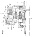
- Fig. 1 shows the automatic transmission 1 thus assembled in a inoperative state
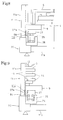
- Fig. 4 is a schematic typical view of the centrifugal friction clutch 10.
- the first spring bearing member 26 is provided on its inner circumference with a projection 26a.
- the projection 26a is spaced a predetermined distance B apart from the carrier 9 while the centrifugal friction clutch 10 is in an inoperative state.
- the deflection S1 (Free length) - (Set length) in a state where the centrifugal friction clutch 10 is inoperative is greater than the length A. Therefore, the centrifugal weights 20 are held in place by the resilience of the springs 25 at a stage of assembling shown in Fig. 7 and hence the centrifugal weights 20 and the springs 25 do not come off the clutch cover 11.
- the friction disks 14 and the clutch disks 15 are abraded and their thickness is reduced by an abrasion thickness loss C. While the abrasion thickness loss C is smaller than the length A, i.e., a distance by which the projections 27a are able to move axially in the circumferential grooves lid, the springs 25 are compressed and hence the springs 25 do not come off the clutch cover 11.
- the deflection S1 the length A and the abrasion thickness loss C must meet an inequality: S1 > A > C.
- the centrifugal friction clutch 10 While the centrifugal friction clutch 10 is in an inoperative state as shown in Figs. 1 and 4, the springs 25 are compressed slightly and the centrifugal friction clutch 10 is engaged lightly.
- the planetary gear 4 When the engine operates at a very low engine speed, the planetary gear 4 is driven by the driving torque of the engine and the component helical gears of the planetary gear 4 produce thrust. Consequently, the friction disks 14 are separated from the clutch disks 15 and hence the centrifugal friction clutch is disengaged.
- the rotation of the input shaft 2 is transmitted to the ring gear 5, the ring gear 5 drives the planet pinions 7 for rotation and revolution around the sun gear 6 which is permitted to rotate only in one direction by the one-way clutch 6a. Consequently, the outer carrier 9 rotates together with the clutch cover 11 and the output member 3.
- the output member 3 (the outer carrier 9) rotates at a rotating speed lower than that of the input shaft 2 (ring gear 5) while the centrifugal friction clutch 10 is disengaged
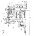
- the centrifugal weights 20 When the rotating speed of the outer carrier 9 is increased to increase traveling speed, the centrifugal weights 20 are turned radially outward as shown in Fig. 2 by centrifugal force and the base portions 20b of the centrifugal weights 20 push and displace the first spring bearing 26 axially against the resilience of the springs 25 as shown in Fig. 2.
- the projection 26a Upon the axial movement of the first spring bearing member 26 by the distance B, the projection 26a comes into contact with the outer carrier 9 restrained from axial movement.
- the centrifugal weights 20 turn further on edges of the inner extremities of the base portions 20b in contact with the first spring bearing member 26, so that outer portions of the base portions 20b in contact with the annular end wall 11b of the clutch cover 11 pushes the clutch cover 11 to the left, as viewed in Fig. 2. Consequently, the clutch cover 11 is moved together with the output member 3 to the left, as viewed in Fig. 1, to compress the friction disks 14 and the clutch disks 15 between the pressure receiving portion 9a of the outer carrier 9 and the pressing portion 3a of the output member 3, so that the centrifugal friction clutch 10 is engaged.
- the automatic transmission 1 is a two-speed transmission that can be set for a low speed when the centrifugal friction clutch 10 is disengaged and for a high speed when the centrifugal friction clutch 10 is engaged.
- the maximum deflection S2 of the springs 25 is determined so as to meet an inequality: S2 > B + C, where B is the distance of free travel of the first spring bearing member 26 and C is the abrasion thickness loss of the friction disks 14 and the clutch disks 15.
- an automatic transmission 31 provided with an centrifugal friction clutch 40 in a second embodiment according to the present invention will be described hereinafter.
- the ring gear 5 is an input member
- the outer carrier 9 is an output member
- the sun gear 6 coupled with the one-way clutch 6a is a fixed member.
- a sun gear is used as an input member and a ring gear is coupled with a one-way clutch and is used as a fixed member.
- the automatic transmission 31 is provided with a planetary gear 34 including a sun gear 35 formed integrally with an input shaft 32, a ring gear 36 connected through a one-way clutch 36a to a fixed member, planet pinions 37, and a carrier 38 supporting planet pinions 37 and formed integrally with an output shaft 33.
- a planetary gear 34 including a sun gear 35 formed integrally with an input shaft 32, a ring gear 36 connected through a one-way clutch 36a to a fixed member, planet pinions 37, and a carrier 38 supporting planet pinions 37 and formed integrally with an output shaft 33.
- the centrifugal friction clutch 40 includes an input member 41 mounted on the input shaft 32 for rotation together with the input shaft 32, friction disks 42 mounted on the input member 41, a clutch cover 45 supported for axial movement on an outer carrier 39 on the outer side of the planet pinions 37, clutch disks 46 arranged on the clutch cover 45, and a pressing member 47 fitted in one end of a cylindrical wall of the clutch cover 45 and retained in place with a snap ring 48.
- the friction disks 42 and the clutch disks 46 are arranged alternately.
- a plurality of rectangular openings are formed in portions of the cylindrical wall of the clutch cover 45 near an annular end wall covering the other end of the cylindrical wall.
- Centrifugal weights 50 are fitted in the rectangular openings, respectively.
- the centrifugal weights 50 are held in place by springs 55 held between a first spring bearing member 56 and a second spring bearing member 57, and placed between the outer carrier 39 and the annular end wall of the clutch cover 45.
- the second spring bearing member 57 is provided on its outer circumference with projections 57a.
- the projections 57a similarly to the projections 27a of the second spring bearing member 27 of the first embodiment, are received in circumferential grooves 45d formed in the inner surface of the clutch cover 45 so as to be axially movable in the circumferential grooves 45d to hold the springs 55 in the clutch cover 45.
- the centrifugal weights 50 are held on the clutch cover 45 by the springs 55 during work for disassembling and assembling the automatic transmission 31, which facilitates work for disassembling and assembling the automatic transmission 31.
- a centrifugal friction clutch 60 in a third embodiment according to the present invention included in an automatic transmission will be described with reference to Figs. 11 and 12, in which parts like or corresponding to those of the first embodiment are denoted by the same reference characters and the description thereof will be omitted.
- the projections 27a of the second spring bearing member 27 are inserted in the circumferential grooves lid to retain the second spring bearing member 27 on the clutch cover 11 such that the springs 25 are compressed and the centrifugal weights 20 are held in place.
- the second spring bearing member 62 is restrained from coming off a clutch cover 61 by a snap ring 63, i.e., second retaining means, put in an annular groove formed in the inner circumference of the clutch cover 61.
- centrifugal friction clutch 60 While the centrifugal friction clutch 60 is in an inoperative state as shown in Fig. 11, the centrifugal friction clutch 60 is engaged lightly because the springs 25 are compressed slightly.
- the planetary gear 4 When the engine operates at a very low engine speed, the planetary gear 4 is driven by the driving torque of the engine and the component helical gears of the planetary gear 4 produce thrust. Consequently, the centrifugal friction clutch 60 is disengaged.
- the output member 3 rotates at a rotating speed lower than that of the input shaft 2 while the centrifugal friction clutch 10 is disengaged.
- a centrifugal friction clutch 70 in a fourth embodiment according to the present invention included in an automatic transmission will be described with reference to Figs. 13 and 14, in which parts like or corresponding to those of the centrifugal friction clutch 10 in the first embodiment are denoted by the same reference characters and the description thereof will be omitted.
- the outer carrier 9 pushes the second spring bearing member 27.
- the position of the outer carrier 9 may be determined so that an appropriate clearance CL can be secured between the outer carrier 9 and the clutch plate 15 nearest to the outer carrier 9.
- an appropriate clearance CL can be secured between the outer carrier 9 and the clutch plate 15 nearest to the outer carrier 9.
- the centrifugal weights 20 are turned radially outward by centrifugal force as shown in Fig. 14 and the clutch cover 71 is moved relative to the outer carrier 9 to reduce the clearance CL to naught, so that the friction disks 14 and the clutch plates 15 are compressed to engage the centrifugal friction clutch 70.
- centrifugal friction clutch 80 in a fifth embodiment according to the present invention is shown in Fig. 15.
- the centrifugal friction clutch 80 is similar to the centrifugal friction clutch 70 in the fourth embodiment and hence parts of the former like or corresponding to those of the latter are denoted by the same reference characters and the description thereof will be omitted.
- the projections 27a of the second spring bearing member 27 are received in the circumferential grooves 71d formed in the inner circumference of the clutch cover 71 to hold the springs 25 on the clutch cover 71.
- a second spring bearing member 83 are retained on a clutch cover 81 by a snap ring 82 as shown in Fig. 15 to hold the springs 25 on the clutch cover 81.
- the second spring bearing member 27 of the fourth embodiment is capable of retaining itself on the clutch cover 71 and hence any part to retain the second spring bearing member 27 on the clutch cover 71 is not necessary.
- the second spring bearing member 27 and the outer carrier 9 have complicated shapes, respectively.
- the fifth embodiment needs the snap ring 82 additionally, the component members have simple shapes, respectively, and hence can be manufactured at low manufacturing costs.
- the first spring bearings 26 and 56 for holding the centrifugal weights 20 and 50 at initial positions have the projections that come into contact with the corresponding outer carriers 9, 39 and 84, and the centrifugal weights 20 and 50 are turned radially outward by centrifugal force to press the first spring bearings 26 and 56 against the outer carriers 9, 39 and 84 restrained from axial movement, respectively, to determine supporting points about which the centrifugal weights 20 and 50 pivot.
- the supporting points about which the centrifugal weights 20 and 50 pivot may be determined without using the first spring bearing members 26 and 56, and the base portions of the centrifugal weights 20 and 50 may be connected by some other members to determine the supporting points for the same.
- connecting members may be extended axially slidably through the first spring bearing 26 and the second spring bearing 27 between the base portions 20b of the centrifugal weights 20 and the outer carrier 9 to press the connecting members by the base portions 20b of the centrifugal weights 20 against the outer carrier 9 restrained from axial movement so that the base portions 20b of the centrifugal weights 20 are supported at support points on outer ends of the connecting members for pivotal movement.
- the connecting members may be those formed integrally with the base portions 20b of the centrifugal weights 20, respectively, or may be those fixed to the outer carrier 9.
- a centrifugal friction clutch for an automatic transmission comprises: friction elements supported on an input member so as to be axially movable and to be rotated together with the input member; clutch cover supported on an output member so as to be axially movable relative to the output member and to rotate together with the output member; clutch elements supported on the clutch cover so as to be axially slidable; centrifugal weights disposed at predetermined positions on the clutch cover; spring members holding the centrifugal weights in place; and first retaining means put in place on the clutch cover to press the friction members and the clutch members against each other so that power can be transmitted when the centrifugal weights are displaced by centrifugal force to move the clutch cover relative to the output member.
- a first spring bearing member placed in contact with one end of each of the spring members urges the centrifugal weights toward their initial positions, and a second spring bearing member placed in contact with the other end of each of the spring members is held in place on the clutch cover by second retaining means engaging the clutch cover.
Landscapes
- Engineering & Computer Science (AREA)
- General Engineering & Computer Science (AREA)
- Mechanical Engineering (AREA)
- One-Way And Automatic Clutches, And Combinations Of Different Clutches (AREA)
Abstract
Description
A plurality of
Claims (3)
- A centrifugal friction clutch for an automatic transmission, comprising:wherein a first spring bearing member placed in contact with one end of each of the spring members urges the centrifugal weights toward their respective predetermined initial positions, and a second spring bearing member placed in contact with the other end of each of the spring members is held in place on the clutch cover by second retaining means engaging the clutch cover.friction elements supported on an input member so as to be axially movable and to be rotated together with the input member;a clutch cover supported on an output member so as to be axially movable relative to the output member and to rotate together with the output member;clutch elements supported on the clutch cover so as to be axially slidable;centrifugal weights disposed at predetermined positions on the clutch cover;spring members holding the centrifugal weights in place on the clutch cover; andfirst retaining means put in place on the clutch cover to press the friction members and the clutch members against each other so that power can be transmitted when the centrifugal weights are displaced by centrifugal force to move the clutch cover relative to the output member;
- The centrifugal friction clutch according to claim 1, wherein the second retaining means is formed integrally with the second spring bearing member.
- The centrifugal friction clutch according to claim 1, wherein the second spring bearing member is not in contact with the output member and is supported on the clutch cover such that a clearance is secured between the output member and the first retaining means.
Applications Claiming Priority (2)
| Application Number | Priority Date | Filing Date | Title |
|---|---|---|---|
| JP36002799A JP2001173683A (en) | 1999-12-17 | 1999-12-17 | Centrifugal friction clutch for automatic transmission |
| JP36002799 | 1999-12-17 |
Publications (3)
| Publication Number | Publication Date |
|---|---|
| EP1108915A2 true EP1108915A2 (en) | 2001-06-20 |
| EP1108915A3 EP1108915A3 (en) | 2003-07-16 |
| EP1108915B1 EP1108915B1 (en) | 2006-05-31 |
Family
ID=18467529
Family Applications (1)
| Application Number | Title | Priority Date | Filing Date |
|---|---|---|---|
| EP00123008A Expired - Lifetime EP1108915B1 (en) | 1999-12-17 | 2000-10-23 | Centrifugal friction clutch for automatic transmission |
Country Status (4)
| Country | Link |
|---|---|
| US (1) | US6422371B1 (en) |
| EP (1) | EP1108915B1 (en) |
| JP (1) | JP2001173683A (en) |
| DE (1) | DE60028329T2 (en) |
Families Citing this family (5)
| Publication number | Priority date | Publication date | Assignee | Title |
|---|---|---|---|---|
| CN100504097C (en) * | 2006-03-28 | 2009-06-24 | 浙江吉利变速器有限公司 | Channel-type clutch |
| US7815539B2 (en) * | 2008-02-27 | 2010-10-19 | The Gates Corporation | Planetary transmission |
| US8047958B2 (en) * | 2009-01-23 | 2011-11-01 | GM Global Technology Operations LLC | Multi-speed transmission having two planetary gear sets |
| CN105247235A (en) * | 2013-05-28 | 2016-01-13 | 舍弗勒技术股份两合公司 | Wedge one-way clutch with gear thrust activation |
| TWI582316B (en) * | 2015-04-24 | 2017-05-11 | yu-xiu Yang | Coaxial fixed surface contact with the passive clutch of the saddle car with dry clutch |
Family Cites Families (10)
| Publication number | Priority date | Publication date | Assignee | Title |
|---|---|---|---|---|
| US2003324A (en) * | 1930-10-15 | 1935-06-04 | Automatic Drive And Transmissi | Automatic clutch device |
| GB401889A (en) * | 1932-11-16 | 1933-11-23 | Noel Banner Newton | Improvements in or relating to centrifugally operated friction clutches |
| US1950581A (en) * | 1933-01-30 | 1934-03-13 | Reo Motor Car Co | Variable speed transmission mechanism |
| US4111291A (en) * | 1977-06-15 | 1978-09-05 | Horstman Manufacturing Co., Inc. | Centrifugal friction mechanism |
| US4732251A (en) * | 1986-09-22 | 1988-03-22 | Tipton Kenneth L | Motorcycle adjustable slider clutch |
| US5409428A (en) * | 1990-02-28 | 1995-04-25 | Antonov Automotive North America B.V. | Centrifugal clutch in a planetary transmission device |
| FR2682646B1 (en) * | 1991-10-18 | 1994-01-14 | Roumen Antonov | AUTOMATIC CLUTCH CONTROL METHOD AND AUTOMATIC TRANSMISSION DEVICE RELATING THERETO. |
| FR2723775A1 (en) * | 1994-08-18 | 1996-02-23 | Antonov Automotive Europ | TRANSMISSION DEVICE, PARTICULARLY FOR VEHICLE, AND DRIVING METHOD RELATING THERETO. |
| FR2729726B1 (en) * | 1995-01-23 | 1997-04-18 | Antonov Automotive Europ | MULTI-DISC CLUTCH, AUTOMATIC TRANSMISSION THUS EQUIPPED AND METHOD FOR PRODUCING THE SAME |
| JP3207719B2 (en) * | 1995-06-30 | 2001-09-10 | 本田技研工業株式会社 | Centrifugal friction clutch for automatic transmission |
-
1999
- 1999-12-17 JP JP36002799A patent/JP2001173683A/en active Pending
-
2000
- 2000-10-23 DE DE60028329T patent/DE60028329T2/en not_active Expired - Fee Related
- 2000-10-23 EP EP00123008A patent/EP1108915B1/en not_active Expired - Lifetime
- 2000-11-02 US US09/703,680 patent/US6422371B1/en not_active Expired - Fee Related
Also Published As
| Publication number | Publication date |
|---|---|
| JP2001173683A (en) | 2001-06-26 |
| EP1108915B1 (en) | 2006-05-31 |
| DE60028329D1 (en) | 2006-07-06 |
| DE60028329T2 (en) | 2006-11-02 |
| US6422371B1 (en) | 2002-07-23 |
| EP1108915A3 (en) | 2003-07-16 |
Similar Documents
| Publication | Publication Date | Title |
|---|---|---|
| US4594915A (en) | Cycloid transmission assembly | |
| US5853073A (en) | Ratchet one-way clutch assembly | |
| US20220364612A1 (en) | Power Transmission Device | |
| US4457185A (en) | Rotational speed controlling device for automatic transmissions using sliding engagement piece | |
| KR0185772B1 (en) | Continuously variable transmission | |
| JP3772736B2 (en) | Planetary gear unit | |
| EP3892878A1 (en) | Power transmission device | |
| JP4135345B2 (en) | Automatic clutch release device and clutch device | |
| EP1108915B1 (en) | Centrifugal friction clutch for automatic transmission | |
| JPS629028A (en) | Vehicle clutch device | |
| JP2620490B2 (en) | Belt converter | |
| US6024197A (en) | Support structure for clutch hub | |
| US4947969A (en) | Center load clutch brake | |
| US5642958A (en) | Engagement structure of connecting shell | |
| JPS5839868A (en) | Belt type automatic speed change gear | |
| US5976049A (en) | Supporting wall structure of toroidal type infinitely variable automatic transmission | |
| EP0028140A1 (en) | Automatic transmissions | |
| JP2001200911A (en) | Axial positioning structure of fixed member | |
| US20040180742A1 (en) | Power transmission device | |
| US7007781B2 (en) | One-way clutch unit and one-way clutch therefor | |
| EP0283855B1 (en) | Auxiliary drive apparatus | |
| JP2836319B2 (en) | Fluid transmission with lock-up clutch | |
| JPS6335850B2 (en) | ||
| JPH08121548A (en) | Two-speed transmission | |
| JP2554336Y2 (en) | Automatic centrifugal clutch |
Legal Events
| Date | Code | Title | Description |
|---|---|---|---|
| PUAI | Public reference made under article 153(3) epc to a published international application that has entered the european phase |
Free format text: ORIGINAL CODE: 0009012 |
|
| AK | Designated contracting states |
Kind code of ref document: A2 Designated state(s): AT BE CH CY DE DK ES FI FR GB GR IE IT LI LU MC NL PT SE |
|
| AX | Request for extension of the european patent |
Free format text: AL;LT;LV;MK;RO;SI |
|
| PUAL | Search report despatched |
Free format text: ORIGINAL CODE: 0009013 |
|
| AK | Designated contracting states |
Designated state(s): AT BE CH CY DE DK ES FI FR GB GR IE IT LI LU MC NL PT SE |
|
| AX | Request for extension of the european patent |
Extension state: AL LT LV MK RO SI |
|
| 17P | Request for examination filed |
Effective date: 20030630 |
|
| AKX | Designation fees paid |
Designated state(s): DE FR GB |
|
| GRAP | Despatch of communication of intention to grant a patent |
Free format text: ORIGINAL CODE: EPIDOSNIGR1 |
|
| GRAS | Grant fee paid |
Free format text: ORIGINAL CODE: EPIDOSNIGR3 |
|
| GRAA | (expected) grant |
Free format text: ORIGINAL CODE: 0009210 |
|
| AK | Designated contracting states |
Kind code of ref document: B1 Designated state(s): DE FR GB |
|
| REG | Reference to a national code |
Ref country code: GB Ref legal event code: FG4D |
|
| REF | Corresponds to: |
Ref document number: 60028329 Country of ref document: DE Date of ref document: 20060706 Kind code of ref document: P |
|
| PGFP | Annual fee paid to national office [announced via postgrant information from national office to epo] |
Ref country code: GB Payment date: 20061018 Year of fee payment: 7 |
|
| PGFP | Annual fee paid to national office [announced via postgrant information from national office to epo] |
Ref country code: DE Payment date: 20061019 Year of fee payment: 7 |
|
| ET | Fr: translation filed | ||
| PLBE | No opposition filed within time limit |
Free format text: ORIGINAL CODE: 0009261 |
|
| STAA | Information on the status of an ep patent application or granted ep patent |
Free format text: STATUS: NO OPPOSITION FILED WITHIN TIME LIMIT |
|
| 26N | No opposition filed |
Effective date: 20070301 |
|
| GBPC | Gb: european patent ceased through non-payment of renewal fee |
Effective date: 20071023 |
|
| PG25 | Lapsed in a contracting state [announced via postgrant information from national office to epo] |
Ref country code: DE Free format text: LAPSE BECAUSE OF NON-PAYMENT OF DUE FEES Effective date: 20080501 |
|
| REG | Reference to a national code |
Ref country code: FR Ref legal event code: ST Effective date: 20080630 |
|
| PGFP | Annual fee paid to national office [announced via postgrant information from national office to epo] |
Ref country code: FR Payment date: 20061010 Year of fee payment: 7 |
|
| PG25 | Lapsed in a contracting state [announced via postgrant information from national office to epo] |
Ref country code: GB Free format text: LAPSE BECAUSE OF NON-PAYMENT OF DUE FEES Effective date: 20071023 |
|
| PG25 | Lapsed in a contracting state [announced via postgrant information from national office to epo] |
Ref country code: FR Free format text: LAPSE BECAUSE OF NON-PAYMENT OF DUE FEES Effective date: 20071031 |