EP1108867A2 - Three-way valve - Google Patents
Three-way valve Download PDFInfo
- Publication number
- EP1108867A2 EP1108867A2 EP00126745A EP00126745A EP1108867A2 EP 1108867 A2 EP1108867 A2 EP 1108867A2 EP 00126745 A EP00126745 A EP 00126745A EP 00126745 A EP00126745 A EP 00126745A EP 1108867 A2 EP1108867 A2 EP 1108867A2
- Authority
- EP
- European Patent Office
- Prior art keywords
- way valve
- throttle body
- valve
- internal combustion
- combustion engine
- Prior art date
- Legal status (The legal status is an assumption and is not a legal conclusion. Google has not performed a legal analysis and makes no representation as to the accuracy of the status listed.)
- Withdrawn
Links
Images


Classifications
-
- F—MECHANICAL ENGINEERING; LIGHTING; HEATING; WEAPONS; BLASTING
- F01—MACHINES OR ENGINES IN GENERAL; ENGINE PLANTS IN GENERAL; STEAM ENGINES
- F01P—COOLING OF MACHINES OR ENGINES IN GENERAL; COOLING OF INTERNAL-COMBUSTION ENGINES
- F01P7/00—Controlling of coolant flow
- F01P7/14—Controlling of coolant flow the coolant being liquid
- F01P7/16—Controlling of coolant flow the coolant being liquid by thermostatic control
- F01P7/167—Controlling of coolant flow the coolant being liquid by thermostatic control by adjusting the pre-set temperature according to engine parameters, e.g. engine load, engine speed
-
- F—MECHANICAL ENGINEERING; LIGHTING; HEATING; WEAPONS; BLASTING
- F16—ENGINEERING ELEMENTS AND UNITS; GENERAL MEASURES FOR PRODUCING AND MAINTAINING EFFECTIVE FUNCTIONING OF MACHINES OR INSTALLATIONS; THERMAL INSULATION IN GENERAL
- F16K—VALVES; TAPS; COCKS; ACTUATING-FLOATS; DEVICES FOR VENTING OR AERATING
- F16K11/00—Multiple-way valves, e.g. mixing valves; Pipe fittings incorporating such valves
- F16K11/02—Multiple-way valves, e.g. mixing valves; Pipe fittings incorporating such valves with all movable sealing faces moving as one unit
- F16K11/08—Multiple-way valves, e.g. mixing valves; Pipe fittings incorporating such valves with all movable sealing faces moving as one unit comprising only taps or cocks
- F16K11/087—Multiple-way valves, e.g. mixing valves; Pipe fittings incorporating such valves with all movable sealing faces moving as one unit comprising only taps or cocks with spherical plug
- F16K11/0873—Multiple-way valves, e.g. mixing valves; Pipe fittings incorporating such valves with all movable sealing faces moving as one unit comprising only taps or cocks with spherical plug the plug being only rotatable around one spindle
-
- G—PHYSICS
- G05—CONTROLLING; REGULATING
- G05D—SYSTEMS FOR CONTROLLING OR REGULATING NON-ELECTRIC VARIABLES
- G05D23/00—Control of temperature
- G05D23/01—Control of temperature without auxiliary power
- G05D23/13—Control of temperature without auxiliary power by varying the mixing ratio of two fluids having different temperatures
- G05D23/1393—Control of temperature without auxiliary power by varying the mixing ratio of two fluids having different temperatures characterised by the use of electric means
-
- F—MECHANICAL ENGINEERING; LIGHTING; HEATING; WEAPONS; BLASTING
- F01—MACHINES OR ENGINES IN GENERAL; ENGINE PLANTS IN GENERAL; STEAM ENGINES
- F01P—COOLING OF MACHINES OR ENGINES IN GENERAL; COOLING OF INTERNAL-COMBUSTION ENGINES
- F01P7/00—Controlling of coolant flow
- F01P7/14—Controlling of coolant flow the coolant being liquid
- F01P2007/143—Controlling of coolant flow the coolant being liquid using restrictions
-
- F—MECHANICAL ENGINEERING; LIGHTING; HEATING; WEAPONS; BLASTING
- F01—MACHINES OR ENGINES IN GENERAL; ENGINE PLANTS IN GENERAL; STEAM ENGINES
- F01P—COOLING OF MACHINES OR ENGINES IN GENERAL; COOLING OF INTERNAL-COMBUSTION ENGINES
- F01P7/00—Controlling of coolant flow
- F01P7/14—Controlling of coolant flow the coolant being liquid
- F01P2007/146—Controlling of coolant flow the coolant being liquid using valves
Definitions
- the invention is based on a three-way valve according to the preamble of claim 1.
- DE 41 09 498 A1 describes an apparatus and a method for a very sensitive regulation of the temperature of a Internal combustion engine known.
- a control device several input signals, e.g. the temperature of the Internal combustion engine, the speed and load of the internal combustion engine, the vehicle speed, the operating state of a Air conditioning or the heating of the vehicle and the temperature of the cooling water.
- a setpoint generator of Control device determines taking into account the input signals a temperature setpoint for the internal combustion engine. According to a comparison of the actual values with the The control device acts on a three-way valve that in the mouth area of a bypass line in a Pipe between the internal combustion engine and a cooler is arranged. Depending on the position of the three-way valve, the Inlet flow divided between the cooling branch and the bypass.
- chick valves in the form of ball valves for setting a specific one Mixing ratio known. They are usually external driven.
- a valve plug, a throttle body is preferably with a spherical surface and with at least provided a distribution channel.
- the throttle body is in a geometrically aligned bearing bed in a valve body stored.
- the spherical throttle body is with a Drive shaft connected to the outside of the valve body is guided and is adjustable by a drive. Corresponding the position of the throttle body, the paths to the outgoing lines released, throttled or blocked.
- the ball valves are made up of individual Components assembled, with the body made of various stainless steel alloys, Gray cast iron, nodular cast iron, stainless steel cast iron, cast steel, aluminum alloys, PVC, PP, PVDF, PTFE, titanium or brass can exist. At the connection points to the lines there are seals made of fluoroplastic, ceramic, nitrile rubber, Pure elastic graphite or POM, which in turn is in Combination with different body materials a high Generate frictional torque so that high positioning forces are required and the setting is delayed.
- the throttle body of the three-way valve formed as a valve plug at least one has it penetrating distribution channel and is powered by an electric motor about the axis of rotation corresponding to one of the control unit assigned map adjustable.
- a three-way valve whose Throttle body has a spherical surface and an inner one Has distribution channel. This runs across the axis of rotation and is on a lateral surface essentially parallel to the axis of rotation open while the opposite lateral surface is closed is.
- the so formed sideways Ball valve flowing towards the axis of rotation has a comparison a more ideal solution for the ball valves flowing from below Mixing characteristic. This can be due to favorable deflection effects by the inclination of the baffle on the throttle body in returned to the areas between 60 ° and 120 ° ball rotation become. Due to the favorable characteristics and flow conditions the three-way valve is suitable for cooling circuits with electrically operated pumps. These can be smaller be dimensioned so that their power consumption is reduced and the overall efficiency improves.
- the three-way valve is operated by an electric motor via a drive shaft operated.
- This is non-rotatable with the throttle body connected; expediently it is directly on the throttle body molded while its free end is detachable with the Electric motor is connected.
- the three-way valve is advantageously a flange valve executed and mounted directly on the internal combustion engine, e.g. on the cylinder head.
- This arrangement eliminates Hose connections and the assembly effort is low. in the The area of the connections faces the valve body to the throttle body out seals made of plastic, which at the same time to Serve the throttle body.
- a spring element in shape of elastomer element, disc spring, star spring or variants of this, keeps the sealing bandage under a defined preload. On the one hand, this ensures a good seal and on the other hand tolerances or wear be balanced.
- the three-way valve is preferably in the assembly injection molding process manufactured, namely the throttle body with the Drive shaft in a first production step as an injection molded part made of thermoplastic.
- the part remains in the injection molding machine and comes with a release agent sprayed, so that in a second injection molding process introduced thermoplastic for the valve body does not connect to the throttle body and this in later valve body is rotatably mounted.
- the use of a two-component injection molding process is also possible in principle. This method is applied to by different material properties of the two injection molded parts e.g. a better friction pairing or to achieve a cheaper valve.
- a metallic one Throttle body with drive shaft or a throttle body made of plastic, which with a suitable plastic overmolded is also conceivable.
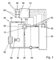
- An inlet line 34 leads from an internal combustion engine 50 for coolant to a cooler 62 which is electrically connected to a driven blower 66 cooperates.
- a return line 36 in which an electrically driven pump 64 is arranged connects the cooler 62 to the internal combustion engine 50 and thus closes a cooling circuit 48.
- On the cooling circuit 48 can a heating circuit, not shown a vehicle heating or air conditioning system.
- a bypass line 38 connects the inlet line 34 to the Return line 36. It bridges the cooler 62 and opens upstream of the pump 64 in the return line 36. Die Coolant flow is indicated by arrows.
- a three-way valve 10 is provided in the form of a plug valve, the throttle body 12 (Fig. 2) by an electric motor 54 is adjustable. This is done by a control unit 52 controlled, which via signal lines 68 with numerous, different sensors 60 is connected. The sensors 60 record operating parameters and environmental parameters of the Internal combustion engine 50 and the cooling / heating circuit 48. Off the input variables are assigned with the help of at least one Characteristic map generated a manipulated variable for the electric motor 54.
- the three-way valve 10 essentially consists from a valve body 14 and the throttle body 12 (Fig. 2). In the embodiment shown, it has a spherical shape Surface. But there are also other surface shapes conceivable, such as cylindrical or conical.
- the throttle body 12 is advantageously an injection molded part made of a thermoplastic.
- a drive shaft 16 is injection molded in one operation and an inner distribution channel 30 and a bore 42 for receiving a temperature sensor 18 formed by insert parts, which are inserted into the mold before injection molding.
- the temperature sensor 18, which is diametrical to the drive shaft 16 is arranged and protrudes into the distribution channel 30 is on easily integrated and detected in the three-way valve 10 the coolant temperature immediately in this range, i.e. in the immediate vicinity of the engine 50 if that Three-way valve 10 by means of screws passing through screw holes 70 are guided in the valve body 14, at a coolant outlet opening flanged to the internal combustion engine 50 is.
- the distribution channel 30 extends transversely to an axis of rotation 20 of the Throttle body 12 and is on a substantially to the axis of rotation 20 parallel lateral surface 56 open while he at the opposite lateral surface 58 is closed.
- the throttle body 12 can also be a core made of a metallic Have material that e.g. manufactured in the die casting process and has a plastic coating.
- the valve body 14 forms the outer part of the three-way valve 10 and is conveniently injection molded by assembly made of thermoplastic.
- the valve body 14 has a connection 22 for the Internal combustion engine 50 coming part of the feed line 34, a connection 24 for the part leading to the cooler 62 Inlet line 34 and a connection 26 for the bypass line 38.
- the connections 22, 24, 26 are perpendicular in one plane to the axis of rotation 20. You are in a simple manner by insert parts molded in the injection mold.
- the valve body 14 in the embodiment according to FIG. 4 towards the throttle body 12 separate sealing rings 32, which are preferably made of tetrafluoroethylene exist and at the same time as storage for the throttle body 12 serve.
- the sealing ring 32 is in the area of Port 26 held by a sleeve 40 which on a End face 44 abuts the sealing ring 32.
- the sleeve 40 will again by a coil spring 28, which is located on a contact surface 46 is supported on the valve body 14, on the sealing ring 32 pressed.
- Fig. 2 and Fig. 3 show the principle of action of a side flow Three-way valve 10.
- the throttle body When the throttle body is in position 12 in Fig. 2, the maximum flow is achieved by the connection 22 through which the coolant flows, both with the connection 24 to the cooler 62 as well as with the connection 26 is connected to the bypass line 38.
- the connection 24 to the cooler 62 When the The throttle body 12 in FIG. 3 is the connection 24 to the cooler 62 blocked and the entire coolant flow is via the bypass line 38 headed. Intermediate positions are also possible so that the coolant flow arbitrarily on a circuit branch via the cooler 62 and a circuit branch via the bypass line 38 according to an associated map can be divided.
Abstract
Description
Die Erfindung geht von einem Dreiwegeventil nach dem Oberbegriff des Anspruchs 1 aus.The invention is based on a three-way valve according to the preamble of claim 1.
Aus der DE 41 09 498 A1 ist eine Vorrichtung und ein Verfahren zu einer sehr feinfühligen Regelung der Temperatur einer Brennkraftmaschine bekannt. Hierzu werden einer Steuereinrichtung mehrere Eingangssignale, wie z.B. die Temperatur der Brennkraftmaschine, die Drehzahl und Last der Brennkraftmaschine, die Fahrzeuggeschwindigkeit, der Betriebszustand einer Klimaanlage bzw. der Heizung des Fahrzeugs und die Temperatur des Kühlwassers, zugeleitet. Ein Sollwertgeber der Steuereinrichtung ermittelt unter Berücksichtigung der Eingangssignale einen Temperatursollwert für die Brennkraftmaschine. Entsprechend einem Vergleich der Istwerte mit den Sollwerten wirkt die Steuereinrichtung auf ein Dreiwegeventil, das im Mündungsbereich einer Bypassleitung in einer Rohrleitung zwischen der Brennkraftmaschine und einem Kühler angeordnet ist. Je nach Stellung des Dreiwegeventils wird der Zulaufstrom auf den Kühlzweig und auf den Bypass aufgeteilt. Damit wird eine Kühlung der Brennkraftmaschine nicht nur in Abhängigkeit von unmittelbar für die Temperaturentwicklung wichtigen Betriebsparametern erfaßt, sondern auch in Abhängigkeit von Parametern von Zusatzaggregaten, die die Temperatur nur mittelbar beeinflussen. Weiterhin werden die Möglichkeiten der Einstellung der optimalen Temperatur wesentlich erweitert, weil auch Störungen erfaßt und berücksichtigt werden können. Durch die Zuordnung verschiedener Einsatzbedingungen zu unterschiedlichen Bereichen von Temperatursollwerten ist eine schnelle Einstellung der gewünschten Temperatur möglich, was durch unterschiedliche Prioritäten der Einsatzbedingungen weiter verfeinert werden kann.DE 41 09 498 A1 describes an apparatus and a method for a very sensitive regulation of the temperature of a Internal combustion engine known. For this purpose, a control device several input signals, e.g. the temperature of the Internal combustion engine, the speed and load of the internal combustion engine, the vehicle speed, the operating state of a Air conditioning or the heating of the vehicle and the temperature of the cooling water. A setpoint generator of Control device determines taking into account the input signals a temperature setpoint for the internal combustion engine. According to a comparison of the actual values with the The control device acts on a three-way valve that in the mouth area of a bypass line in a Pipe between the internal combustion engine and a cooler is arranged. Depending on the position of the three-way valve, the Inlet flow divided between the cooling branch and the bypass. This does not only cool the internal combustion engine Dependence on immediate for temperature development important operating parameters, but also dependent of parameters of auxiliary units that determine the temperature influence only indirectly. The possibilities continue the setting of the optimal temperature is essential expanded because faults are also recorded and taken into account can. By assigning different operating conditions to different ranges of temperature setpoints is a quick setting of the desired temperature possible, due to different priorities of the operating conditions can be further refined.
Es ist weiterhin bekannt, im Kühlkreislauf der Brennkraftmaschine die Kühlmitteltemperatur mit Hilfe eines Thermostatventils zu regeln. Dabei wird das Mischverhältnis zwischen einer Zulaufleitung zum Kühler und einer Bypassleitung durch ein dehnstoffgetriebenes Thermostatventil in Abhängigkeit der Kühlmitteltemperatur eingestellt. Nachteilig ist allerdings, daß die Regelung träge ist und nur über die Kühlmitteltemperatur und nicht extern bzw. von einer übergeordneten Steuereinheit erfolgt. Viele Einflußgrößen werden dadurch erst nach der Veränderung der Kühlmitteltemperatur und demzufolge mit Verzögerung wirksam.It is also known in the cooling circuit of the internal combustion engine the coolant temperature using a thermostatic valve to regulate. The mixing ratio between an inlet line to the cooler and a bypass line an expansion-driven thermostatic valve depending on the Coolant temperature set. The disadvantage is that the control is slow and only on the coolant temperature and not externally or from a higher-level control unit he follows. This means that many influencing factors only become apparent the change in coolant temperature and consequently with Delay effective.
Aus anderen Bereichen, wie beispielsweise der Chemie, der Papierherstellung oder der Mineralölförderung, sind Kükenventile in Form von Kugelventilen zur Einstellung eines bestimmten Mischverhältnisses bekannt. Sie werden in der Regel extern angetrieben. Ein Ventilküken, ein Drosselkörper, ist vorzugsweise mit einer kugelförmigen Oberfläche und mit mindestens einem Verteilerkanal versehen. Der Drosselkörper ist in einem geometrisch angeglichenen Lagerbett in einem Ventilkörper gelagert. Der kugelförmige Drosselkörper ist mit einer Antriebswelle verbunden, die aus dem Ventilkörper nach außen geführt ist und durch einen Antrieb verstellbar ist. Entsprechend der Stellung des Drosselkörpers werden die Wege zu den weiterführenden Leitungen freigegeben, gedrosselt bzw. versperrt. In der Regel werden die Kugelventile aus einzelnen Komponenten montiert, wobei die Körper aus diversen Edelstahllegierungen, Grauguß, Sphäroguß, Niroguß, Stahlguß, Aluminiumlegierungen, PVC, PP, PVDF, PTFE, Titan oder Messing bestehen können. An den Verbindungsstellen zu den Leitungen befinden sich Dichtungen aus Fluorkunststoff, Keramik, Nitrilkautschuk, Reinstelastikgraphit oder POM, die wiederum in Kombination mit verschiedenen Körperwerkstoffen ein hohes Reibmoment erzeugen, so daß hohe Stellkräfte erforderlich sind und die Einstellung verzögert wird.From other areas, such as chemistry, the Papermaking or mineral oil production are chick valves in the form of ball valves for setting a specific one Mixing ratio known. They are usually external driven. A valve plug, a throttle body, is preferably with a spherical surface and with at least provided a distribution channel. The throttle body is in a geometrically aligned bearing bed in a valve body stored. The spherical throttle body is with a Drive shaft connected to the outside of the valve body is guided and is adjustable by a drive. Corresponding the position of the throttle body, the paths to the outgoing lines released, throttled or blocked. As a rule, the ball valves are made up of individual Components assembled, with the body made of various stainless steel alloys, Gray cast iron, nodular cast iron, stainless steel cast iron, cast steel, aluminum alloys, PVC, PP, PVDF, PTFE, titanium or brass can exist. At the connection points to the lines there are seals made of fluoroplastic, ceramic, nitrile rubber, Pure elastic graphite or POM, which in turn is in Combination with different body materials a high Generate frictional torque so that high positioning forces are required and the setting is delayed.
Nach der Erfindung ist der Drosselkörper des Dreiwegeventils als Ventilküken ausgebildet, weist mindestens einen ihn durchdringenden Verteilerkanal auf und ist durch einen Elektromotor um die Drehachse entsprechend einem der Steuereinheit zugeordneten Kennfeld verstellbar.According to the invention, the throttle body of the three-way valve formed as a valve plug, at least one has it penetrating distribution channel and is powered by an electric motor about the axis of rotation corresponding to one of the control unit assigned map adjustable.
Im Gegensatz zu magnetisch betätigten Ventilen, arbeitet das erfindungsgemäße Dreiwegeventil geräuschlos. Ferner besitzt es über den Stellwinkel des Drosselkörpers eine nahezu lineare Kennlinie des Volumenstroms und des Mischungsverhältnisses, so daß über ein zugeordnetes Kennfeld die Position für einen optimalen Kühlmittelvolumenstrom und die Kühlmitteltemperatur angesteuert werden kann. Dadurch kann die Wärmeregelung, die häufig durch lange Todzeiten im allgemeinen träge ist, wesentlich beschleunigt werden. In contrast to solenoid operated valves, it works Three-way valve according to the invention noiseless. Also owns it is almost linear over the setting angle of the throttle body Characteristic curve of the volume flow and the mixing ratio, so that the position for an optimal coolant volume flow and the coolant temperature can be controlled. Thereby the heat control, which is generally sluggish due to long periods of death is significantly accelerated.
Besonders eignet sich hierfür ein Dreiwegeventil, dessen Drosselkörper eine kugelförmige Oberfläche und einen inneren Verteilerkanal hat. Dieser verläuft quer zur Drehachse und ist an einer im wesentlichen zur Drehachse parallelen Mantelfläche offen, während die gegenüberliegende Mantelfläche geschlossen ist. Durch Drehen der Kugel wird entweder der Kreislauf über den Kühler oder der Kreislauf über die Bypassleitung mehr oder weniger freigegeben. Das so gebildete seitlich zur Drehachse angeströmte Kugelventil weist im Vergleich zu den von unten angeströmten Kugelventilen eine idealere Mischkennlinie auf. Dies kann auf günstige Umlenkeffekte durch die Schrägstellung der Prallfläche am Drosselkörper in den Bereichen zwischen 60° und 120° Kugeldrehung zurückgeführt werden. Durch die günstigen Kennlinien und Strömungsverhältnisse eignet sich das Dreiwegeventil für Kühlkreisläufe mit elektrisch betriebenen Pumpen. Diese können kleiner dimensioniert werden, so daß sich ihre Leistungsaufnahme verringert und sich der Gesamtwirkungsgrad verbessert.A three-way valve, whose Throttle body has a spherical surface and an inner one Has distribution channel. This runs across the axis of rotation and is on a lateral surface essentially parallel to the axis of rotation open while the opposite lateral surface is closed is. By turning the ball either Circuit via the cooler or the circuit via the bypass line released more or less. The so formed sideways Ball valve flowing towards the axis of rotation has a comparison a more ideal solution for the ball valves flowing from below Mixing characteristic. This can be due to favorable deflection effects by the inclination of the baffle on the throttle body in returned to the areas between 60 ° and 120 ° ball rotation become. Due to the favorable characteristics and flow conditions the three-way valve is suitable for cooling circuits with electrically operated pumps. These can be smaller be dimensioned so that their power consumption is reduced and the overall efficiency improves.
Das Dreiwegeventil wird von einem Elektromotor über eine Antriebswelle betätigt. Diese ist drehfest mit dem Drosselkörper verbunden; zweckmäßigerweise ist sie unmittelbar am Drosselkörper angespritzt, während ihr freies Ende lösbar mit dem Elektromotor verbunden wird.The three-way valve is operated by an electric motor via a drive shaft operated. This is non-rotatable with the throttle body connected; expediently it is directly on the throttle body molded while its free end is detachable with the Electric motor is connected.
Vorteilhafterweise ist das Dreiwegeventil als Flanschventil ausgeführt und direkt an der Brennkraftmaschine montiert, z.B. am Zylinderkopf. Durch diese Anordnung entfallen Schlauchverbindungen und der Montageaufwand ist gering. Im Bereich der Anschlüsse weist der Ventilkörper zum Drosselkörper hin Dichtungen aus Kunststoff auf, die gleichzeitig zur Lagerung des Drosselkörpers dienen. Ein Federelement, in Form von Elastomerelement, Tellerfeder, Sternfeder oder Varianten davon, hält den Dichtverband unter einer definierten Vorspannung. Dadurch ist einerseits eine gute Abdichtung gewährleistet und andererseits können Toleranzen bzw. der Verschleiß ausgeglichen werden.The three-way valve is advantageously a flange valve executed and mounted directly on the internal combustion engine, e.g. on the cylinder head. This arrangement eliminates Hose connections and the assembly effort is low. in the The area of the connections faces the valve body to the throttle body out seals made of plastic, which at the same time to Serve the throttle body. A spring element, in shape of elastomer element, disc spring, star spring or variants of this, keeps the sealing bandage under a defined preload. On the one hand, this ensures a good seal and on the other hand tolerances or wear be balanced.
Das Dreiwegeventil wird vorzugsweise im Montagespritzgußverfahren hergestellt, und zwar wird der Drosselkörper mit der Antriebswelle in einem ersten Fertigungsschritt als Spritzgußteil aus thermoplastischem Kunststoff erzeugt. Das Teil verbleibt in der Spritzgußmaschine und wird mit einem Trennmittel besprüht, damit sich der in einem zweiten Spritzgießprozeß eingebrachte thermoplastische Kunststoff für den Ventilkörper nicht mit dem Drosselkörper verbindet und dieser im späteren Ventilkörper drehbar gelagert ist. Vorzugsweise werden für dieses Verfahren gleiche Kunststoffe für die Spritzgußteile verwendet, um eine sortenreine Wiederverwertung zu gewährleisten. Der Einsatz eines Zweikomponenten-Spritzgußverfahrens ist prinzipiell aber auch möglich. Dieses Verfahren wird angewendet, um durch unterschiedliche Materialeigenschaften der beiden Spritzgußteile z.B. eine bessere Reibpaarung oder ein kostengünstigeres Ventil zu erzielen. Ein metallischer Drosselkörper mit Antriebswelle oder ein Drosselkörper aus Kunststoff, welche mit einem geeigneten Kunststoff umspritzt werden, ist ebenfalls denkbar.The three-way valve is preferably in the assembly injection molding process manufactured, namely the throttle body with the Drive shaft in a first production step as an injection molded part made of thermoplastic. The part remains in the injection molding machine and comes with a release agent sprayed, so that in a second injection molding process introduced thermoplastic for the valve body does not connect to the throttle body and this in later valve body is rotatably mounted. Preferably be same plastics for the injection molded parts for this process used to separate recycling guarantee. The use of a two-component injection molding process is also possible in principle. This method is applied to by different material properties of the two injection molded parts e.g. a better friction pairing or to achieve a cheaper valve. A metallic one Throttle body with drive shaft or a throttle body made of plastic, which with a suitable plastic overmolded is also conceivable.
Wenn auf separate Dichtungen nicht verzichtet werden kann, können diese vor dem Spritzgießvorgang im Werkzeug positioniert und teilweise umspritzt werden. Durch das vorgeschlagene Verfahren entfallen Montagearbeiten und der Fertigungsaufwand der Bauteile reduziert sich wesentlich, zumal wenn der Ventilkörper und der Drosselkörper ohne spanende Fertigungsverfahren produziert werden. Das Fertigungsverfahren ist besonders für Ventilküken mit einer kugelförmigen Oberfläche vorteilhaft, die sonst nur aufwendig herzustellen sind.If there is no need for separate seals, can be positioned in the mold before the injection molding process and partially overmolded. Through the proposed There is no need for assembly work and manufacturing costs the components are significantly reduced, especially if the Valve body and the throttle body without machining processes to be produced. The manufacturing process is special for valve blocks with a spherical surface advantageous, which are otherwise only expensive to manufacture.
Weitere Vorteile ergeben sich aus der folgenden Zeichnungsbeschreibung. In der Zeichnung ist ein Ausführungsbeispiel der Erfindung dargestellt. Die Zeichnung, die Beschreibung und die Ansprüche enthalten zahlreiche Merkmale in Kombination. Der Fachmann wird die Merkmale zweckmäßigerweise auch einzeln betrachten und zu sinnvollen weiteren Kombinationen zusammenfassen.Further advantages result from the following description of the drawing. In the drawing, an embodiment of the Invention shown. The drawing, the description and the claims contain numerous features in combination. The person skilled in the art will also expediently use the features individually consider and combine them into meaningful further combinations.
Es zeigen:
- Fig. 1
- einen schematisch dargestellten Kühlkreislauf einer Brennkraftmaschine,
- Fig. 2
- eine schematische Darstellung des Dreiwegeventils in der Mittelstellung,
- Fig. 3
- eine schematische Darstellung des Dreiwegeventils in einer Endstellung und
- Fig. 4
- eine perspektivische, teilweise geschnittene Darstellung eines erfindungsgemäßen Dreiwegeventils.
- Fig. 1
- a schematically illustrated cooling circuit of an internal combustion engine,
- Fig. 2
- a schematic representation of the three-way valve in the middle position,
- Fig. 3
- a schematic representation of the three-way valve in an end position and
- Fig. 4
- a perspective, partially sectioned illustration of a three-way valve according to the invention.
Von einer Brennkraftmaschine 50 führt eine Zulaufleitung 34
für Kühlmittel zu einem Kühler 62, der mit einem elektrisch
angetriebenen Gebläse 66 zusammenarbeitet. Eine Rücklaufleitung
36 , in der eine elektrisch angetriebene Pumpe 64 angeordnet
ist, verbindet den Kühler 62 mit der Brennkraftmaschine
50 und schließt so einen Kühlkreislauf 48. An dem Kühlkreislauf
48 kann ein nicht näher dargestellter Heizkreislauf
einer Fahrzeugheizung oder Klimaanlage angeschlossen sein.
Eine Bypassleitung 38 verbindet die Zulaufleitung 34 mit der
Rücklaufleitung 36. Sie überbrückt den Kühler 62 und mündet
stromaufwärts der Pumpe 64 in die Rücklaufleitung 36. Die
Kühlmittelströmung ist durch Pfeile angedeutet.An
An der Abzweigung der Bypassleitung 38 von der Zulaufleitung
34 ist ein Dreiwegeventil 10 in Form eines Kükenventils vorgesehen,
dessen Drosselkörper 12 (Fig. 2) durch einen Elektromotor
54 verstellbar ist. Dieser wird von einer Steuereinheit
52 angesteuert, die über Signalleitungen 68 mit zahlreichen,
unterschiedlichen Sensoren 60 verbunden ist. Die Sensoren
60 erfassen Betriebsparameter und Umgebungsparameter der
Brennkraftmaschine 50 und des Kühl-/Heizkreislaufs 48. Aus
den Eingangsgrößen wird mit Hilfe mindestens eines zugeordneten
Kennfeldes eine Stellgröße für den Elektromotor 54 erzeugt.At the branch of the
Das erfindungsgemäße Dreiwegeventil 10 besteht im wesentlichen
aus einem Ventilkörper 14 und dem Drosselkörper 12 (Fig.
2). In der dargestellten Ausführung besitzt er eine kugelförmige
Oberfläche. Es sind aber auch andere Oberflächenformen
denkbar, wie beispielsweise zylindrische oder konische.The three-
Der Drosselkörper 12 ist zweckmäßigerweise ein Spritzgußteil
aus einem thermoplastischen Kunststoff. Vorzugsweise wird
eine Antriebswelle 16 in einem Arbeitsgang angespritzt und
ein innerer Verteilerkanal 30 sowie eine Bohrung 42 zur Aufnahme
eines Temperatursensors 18 durch Einlegeteile ausgeformt,
die vor dem Spritzguß in das Werkzeug eingelegt werden.
Der Temperatursensor 18, der diametral zur Antriebswelle
16 angeordnet ist und in den Verteilerkanal 30 ragt, ist auf
einfache Weise in das Dreiwegeventil 10 integriert und erfaßt
die Kühlmitteltemperatur unmittelbar in diesem Bereich, d.h.
in unmittelbarer Nähe der Brennkraftmaschine 50, wenn das
Dreiwegeventil 10 mittels Schrauben, die durch Schraubenlöcher
70 im Ventilkörper 14 geführt sind, an einer Kühlmittelaustrittsöffnung
an der Brennkraftmaschine 50 angeflanscht
ist.The
Der Verteilerkanal 30 verläuft quer zu einer Drehachse 20 des
Drosselkörpers 12 und ist an einer im wesentlichen zur Drehachse
20 parallelen Mantelfläche 56 offen, während er an der
gegenüberliegende Mantelfläche 58 geschlossen ist. Der Drosselkörper
12 kann aber auch einen Kern aus einem metallischen
Werkstoff haben, der z.B. im Druckgußverfahren hergestellt
ist und eine Kunststoffbeschichtung trägt.The
Der Ventilkörper 14 bildet den äußeren Teil des Dreiwegeventils
10 und wird zweckmäßigerweise durch Montagespritzgießen
aus thermoplastischem Kunststoff erzeugt. Hierzu wird die
Oberfläche des Drosselkörpers 12 mit einer Trennschicht versehen,
so daß sich der Werkstoff des Ventilkörpers 14 beim
anschließenden Montagespritzgießen nicht mit dem Werkstoff
des Drosselkörpers 12 verbindet. Es entstehen so enge Bewegungs-
und Dichtspalte, so daß in der Regel auf separate Lager-
und Dichtelemente verzichtet werden kann.The
Der Ventilkörper 14 besitzt einen Anschluß 22 für den von der
Brennkraftmaschine 50 kommenden Teil der Zulaufleitung 34,
einen Anschluß 24 für den zum Kühler 62 führenden Teil der
Zulaufleitung 34 und einen Anschluß 26 für die Bypassleitung
38. Die Anschlüsse 22, 24, 26 liegen in einer Ebene senkrecht
zur Drehachse 20. Sie werden in einfacher Weise durch Einlegeteile
im Spritzgußwerkzeug ausgeformt.The
Im Bereich der Anschlüsse 24 und 26, die diametral zueinander
liegen oder unter einem kleineren Winkel zueinander und zum
Anschluß (22) angeordnet sein können, weist der Ventilkörper
14 in der Ausführung nach Fig. 4 zum Drosselkörper 12 hin
separate Dichtringe 32 auf, die vorzugsweise aus Tetrafluoräthylen
bestehen und gleichzeitig als Lagerung für den Drosselkörper
12 dienen. Der Dichtring 32 wird im Bereich des
Anschlusses 26 durch eine Hülse 40 gehalten, die an einer
Stirnfläche 44 am Dichtring 32 anliegt. Die Hülse 40 wird
wiederum durch eine Schraubenfeder 28, die sich an einer Anlagefläche
46 am Ventilkörper 14 abstützt, an den Dichtring
32 gepreßt. Auf diese Art wird der Verschleiß an den Dichtringen
32 kompensiert und eine ausreichende Abdichtung über
die gesamte Produktlebensdauer sichergestellt. Wird das Dreiwegeventil
10 im Montagespritzgußverfahren hergestellt, werden
die Dichtringe 32, die Hülse 40 und die Schraubenfeder 28
vor dem Spritzgießen des Ventilkörpers 14 mit einer Trennschicht
umgeben im Werkzeug positioniert und beim Spritzgußvorgang
umspritzt.In the area of the
Fig. 2 und Fig. 3 zeigen das Wirkprinzip eines seitlich angeströmten
Dreiwegeventils 10. Bei der Stellung des Drosselkörpers
12 in Fig. 2 wird der maximale Durchfluß erreicht, indem
der Anschluß 22, durch den das Kühlmittel zuströmt, sowohl
mit dem Anschluß 24 zum Kühler 62 als auch mit dem Anschluß
26 zur Bypassleitung 38 verbunden ist. Bei der Stellung des
Drosselkörpers 12 in Fig. 3 ist der Anschluß 24 zum Kühler 62
gesperrt und der gesamte Kühlmittelstrom wird über die Bypassleitung
38 geleitet. Zwischenstellungen sind auch möglich,
so daß der Kühlmittelstrom beliebig auf einen Kreislaufzweig
über den Kühler 62 und einen Kreislaufzweig über
die Bypassleitung 38 entsprechend einem zugehörigen Kennfeld
aufgeteilt werden kann. Fig. 2 and Fig. 3 show the principle of action of a side flow
Three-
- 1010th
- DreiwegeventilThree-way valve
- 1212th
- DrosselkörperThrottle body
- 1414
- VentilkörperValve body
- 1616
- Antriebswelledrive shaft
- 1818th
- TemperatursensorTemperature sensor
- 2020th
- DrehachseAxis of rotation
- 2222
- AnschlußConnection
- 2424th
- AnschlußConnection
- 2626
- AnschlußConnection
- 2828
- SchraubenfederCoil spring
- 3030th
- VerteilerkanalDistribution channel
- 3232
- DichtringSealing ring
- 3434
- ZulaufleitungInlet pipe
- 3636
- RücklaufleitungReturn line
- 3838
- BypassleitungBypass line
- 4040
- HülseSleeve
- 4242
- Bohrungdrilling
- 4444
- StirnflächeFace
- 4646
- AnlageflächeContact surface
- 4848
- Kühl-/HeizkreislaufCooling / heating circuit
- 5050
- BrennkraftmaschineInternal combustion engine
- 5252
- SteuereinheitControl unit
- 5454
- ElektromotorElectric motor
- 5656
- MantelflächeLateral surface
- 5858
- MantelflächeLateral surface
- 6060
- Sensorsensor
- 6262
- Kühlercooler
- 6464
- Pumpepump
- 6666
- Gebläsefan
- 6868
- SignalleitungSignal line
- 7070
- SchraubenlochScrew hole
Claims (12)
Applications Claiming Priority (2)
| Application Number | Priority Date | Filing Date | Title |
|---|---|---|---|
| DE19960931 | 1999-12-17 | ||
| DE1999160931 DE19960931A1 (en) | 1999-12-17 | 1999-12-17 | Three-way valve |
Publications (2)
| Publication Number | Publication Date |
|---|---|
| EP1108867A2 true EP1108867A2 (en) | 2001-06-20 |
| EP1108867A3 EP1108867A3 (en) | 2003-01-29 |
Family
ID=7933050
Family Applications (1)
| Application Number | Title | Priority Date | Filing Date |
|---|---|---|---|
| EP00126745A Withdrawn EP1108867A3 (en) | 1999-12-17 | 2000-12-06 | Three-way valve |
Country Status (2)
| Country | Link |
|---|---|
| EP (1) | EP1108867A3 (en) |
| DE (1) | DE19960931A1 (en) |
Cited By (14)
| Publication number | Priority date | Publication date | Assignee | Title |
|---|---|---|---|---|
| WO2003042517A1 (en) * | 2001-11-10 | 2003-05-22 | Robert Bosch Gmbh | Valve having an emergency function |
| EP1529937A1 (en) * | 2003-11-06 | 2005-05-11 | ITW Automotive Products GmbH & Co. KG | Cooling system for internal combustion engines, especially for motor vehicles |
| EP1881246A2 (en) * | 2006-07-17 | 2008-01-23 | MHA Zentgraf Merziger Hochdruck Armaturen GmbH & Co. KG | Distributor for distributing a fluid |
| WO2008020282A2 (en) * | 2006-08-16 | 2008-02-21 | Itw Automotive Products Gmbh & Co. Kg | Thermostat valve |
| WO2008151462A1 (en) * | 2007-06-11 | 2008-12-18 | Guosheng Liang | Temperature regulator for internal combustion engine |
| EP2799685A2 (en) | 2013-05-03 | 2014-11-05 | Behr Thermot-tronik GmbH | Electrically driven valve for regulating the volumetric flow rate for a heating and/or cooling system of a motor vehicle |
| CN104685275A (en) * | 2012-07-11 | 2015-06-03 | 伊利诺斯工具制品有限公司 | Thermostat valve |
| EP2647805A3 (en) * | 2012-04-04 | 2015-11-25 | Behr Thermot-tronik GmbH | Thermostatic valve for a combustion engine |
| WO2016037921A1 (en) * | 2014-09-12 | 2016-03-17 | Mahle International Gmbh | Valve for controlling volumetric flows |
| US9429064B2 (en) | 2011-09-22 | 2016-08-30 | Mikuni Corporation | Coolant control valve apparatus |
| WO2017034456A1 (en) * | 2015-08-25 | 2017-03-02 | Scania Cv Ab | Thermostat device |
| EP3730821A1 (en) * | 2019-04-23 | 2020-10-28 | Vitesco Technologies GmbH | Multi-port valve |
| WO2020145921A3 (en) * | 2019-01-10 | 2020-11-12 | Kirpart Otomotiv Parcalari Sanayi Ve Ticaret A.S | A smart thermal management module for engine cooling |
| US20230341062A1 (en) * | 2022-04-25 | 2023-10-26 | Delta Electronics, Inc. | Ball valve |
Families Citing this family (8)
| Publication number | Priority date | Publication date | Assignee | Title |
|---|---|---|---|---|
| DE10127711B4 (en) * | 2001-06-07 | 2007-02-01 | Robert Bosch Gmbh | Three-way valve |
| DE10345614A1 (en) | 2003-09-29 | 2005-05-12 | Bosch Gmbh Robert | Three-way valve |
| DE102005046117B4 (en) * | 2005-09-27 | 2015-06-25 | Robert Bosch Gmbh | Multiway valve for a coolant circuit of an internal combustion engine |
| DE102009009854B4 (en) | 2009-02-20 | 2012-05-24 | Audi Ag | Coolant circuit for an internal combustion engine |
| DE102009025351B4 (en) * | 2009-06-18 | 2015-06-11 | Schaeffler Technologies AG & Co. KG | Control valve for controlling a coolant circuit of an internal combustion engine |
| DE102011003430B3 (en) | 2011-02-01 | 2012-05-31 | Continental Automotive Gmbh | Method and device for checking a control device |
| DE102017117680B4 (en) | 2017-08-03 | 2019-06-27 | M + S Armaturen Gmbh | switching valve |
| DE102017130226A1 (en) | 2017-12-15 | 2019-06-19 | BorgWarner Esslingen GmbH | Control device for a fluid and method for its production |
Citations (1)
| Publication number | Priority date | Publication date | Assignee | Title |
|---|---|---|---|---|
| DE4109498A1 (en) | 1991-03-22 | 1992-09-24 | Bosch Gmbh Robert | Electronic control of IC engine temp. - uses electronically controlled valve in place of thermostat and electronically controlled fan |
Family Cites Families (4)
| Publication number | Priority date | Publication date | Assignee | Title |
|---|---|---|---|---|
| FR2388994A1 (en) * | 1977-04-29 | 1978-11-24 | Sev Marchal | Cooling water circuit for IC engine - has control set by vehicle computer with temp. inputs regulating variable speed motors |
| EP0557113B1 (en) * | 1992-02-19 | 1999-05-26 | Honda Giken Kogyo Kabushiki Kaisha | Engine cooling system |
| JP3644262B2 (en) * | 1998-07-29 | 2005-04-27 | 株式会社デンソー | Cooling device for liquid-cooled internal combustion engine |
| DE10016405A1 (en) * | 2000-04-01 | 2001-10-11 | Bosch Gmbh Robert | Cooling circuit |
-
1999
- 1999-12-17 DE DE1999160931 patent/DE19960931A1/en not_active Ceased
-
2000
- 2000-12-06 EP EP00126745A patent/EP1108867A3/en not_active Withdrawn
Patent Citations (1)
| Publication number | Priority date | Publication date | Assignee | Title |
|---|---|---|---|---|
| DE4109498A1 (en) | 1991-03-22 | 1992-09-24 | Bosch Gmbh Robert | Electronic control of IC engine temp. - uses electronically controlled valve in place of thermostat and electronically controlled fan |
Cited By (27)
| Publication number | Priority date | Publication date | Assignee | Title |
|---|---|---|---|---|
| WO2003042517A1 (en) * | 2001-11-10 | 2003-05-22 | Robert Bosch Gmbh | Valve having an emergency function |
| EP1529937A1 (en) * | 2003-11-06 | 2005-05-11 | ITW Automotive Products GmbH & Co. KG | Cooling system for internal combustion engines, especially for motor vehicles |
| EP1881246A2 (en) * | 2006-07-17 | 2008-01-23 | MHA Zentgraf Merziger Hochdruck Armaturen GmbH & Co. KG | Distributor for distributing a fluid |
| EP1881246A3 (en) * | 2006-07-17 | 2008-01-30 | MHA Zentgraf Merziger Hochdruck Armaturen GmbH & Co. KG | Distributor for distributing a fluid |
| WO2008020282A3 (en) * | 2006-08-16 | 2008-05-08 | Itw Automotive Prod Gmbh & Co | Thermostat valve |
| DE102006038213A1 (en) * | 2006-08-16 | 2008-02-21 | Itw Automotive Products Gmbh & Co. Kg | thermostatic valve |
| DE102006038213B4 (en) * | 2006-08-16 | 2010-11-11 | Itw Automotive Products Gmbh & Co. Kg | thermostatic valve |
| CN101484738B (en) * | 2006-08-16 | 2011-05-25 | Itw汽车产品有限两合公司 | Thermostat valve |
| US7963455B2 (en) | 2006-08-16 | 2011-06-21 | Itw Automotive Products Gmbh & Co. Kg | Thermostat valve |
| WO2008020282A2 (en) * | 2006-08-16 | 2008-02-21 | Itw Automotive Products Gmbh & Co. Kg | Thermostat valve |
| WO2008151462A1 (en) * | 2007-06-11 | 2008-12-18 | Guosheng Liang | Temperature regulator for internal combustion engine |
| US9429064B2 (en) | 2011-09-22 | 2016-08-30 | Mikuni Corporation | Coolant control valve apparatus |
| EP2647805A3 (en) * | 2012-04-04 | 2015-11-25 | Behr Thermot-tronik GmbH | Thermostatic valve for a combustion engine |
| US9951878B2 (en) | 2012-07-11 | 2018-04-24 | Illinois Tool Works Inc. | Thermostat valve |
| CN104685275A (en) * | 2012-07-11 | 2015-06-03 | 伊利诺斯工具制品有限公司 | Thermostat valve |
| DE102013208193A1 (en) | 2013-05-03 | 2014-11-06 | Behr Thermot-Tronik Gmbh | Electrically driven valve for controlling volume flows in a heating and / or cooling system of a motor vehicle |
| EP2799685A2 (en) | 2013-05-03 | 2014-11-05 | Behr Thermot-tronik GmbH | Electrically driven valve for regulating the volumetric flow rate for a heating and/or cooling system of a motor vehicle |
| DE102014218386A1 (en) | 2014-09-12 | 2016-03-17 | Mahle International Gmbh | Valve for a regulation of volume flows |
| WO2016037921A1 (en) * | 2014-09-12 | 2016-03-17 | Mahle International Gmbh | Valve for controlling volumetric flows |
| WO2017034456A1 (en) * | 2015-08-25 | 2017-03-02 | Scania Cv Ab | Thermostat device |
| WO2020145921A3 (en) * | 2019-01-10 | 2020-11-12 | Kirpart Otomotiv Parcalari Sanayi Ve Ticaret A.S | A smart thermal management module for engine cooling |
| EP3730821A1 (en) * | 2019-04-23 | 2020-10-28 | Vitesco Technologies GmbH | Multi-port valve |
| WO2020216610A1 (en) * | 2019-04-23 | 2020-10-29 | Vitesco Technologies GmbH | Multi-way valve |
| CN113710938A (en) * | 2019-04-23 | 2021-11-26 | 纬湃技术有限公司 | Multi-way valve |
| CN113710938B (en) * | 2019-04-23 | 2023-10-24 | 纬湃技术有限公司 | Multi-way valve |
| US11885255B2 (en) | 2019-04-23 | 2024-01-30 | Vitesco Technologies GmbH | Multiport valve |
| US20230341062A1 (en) * | 2022-04-25 | 2023-10-26 | Delta Electronics, Inc. | Ball valve |
Also Published As
| Publication number | Publication date |
|---|---|
| DE19960931A1 (en) | 2001-06-28 |
| EP1108867A3 (en) | 2003-01-29 |
Similar Documents
| Publication | Publication Date | Title |
|---|---|---|
| EP1108867A2 (en) | Three-way valve | |
| DE60127465T2 (en) | ABRASIVE CURRENT PROCESSING DEVICE AND METHOD | |
| DE102006053310A1 (en) | Volume flow controlling valve for heating and/or cooling system of motor vehicle, has valve body including passage openings with rotating angle-dependent opening characteristics, where openings are attached to inlet and outlet channels | |
| DE2705073A1 (en) | THROTTLE VALVE FOR RELEASING THE REFRIGERANT IN THE REFRIGERANT CIRCUIT OF A VEHICLE AIR CONDITIONING SYSTEM | |
| DE102005026685A1 (en) | Inlet manifold and method for its production | |
| EP1272747B1 (en) | Cooling circuit | |
| DE102009025341A1 (en) | Control valve for regulating coolant circuit of internal combustion engine, has two feed connections arranged on valve housing for cooling water of bypass circuit and for cooling water of cooling circuit | |
| DE69817213T2 (en) | THERMOSTAT VALVE | |
| EP2992255B1 (en) | Electrical actuated valve for volume flow control in a heating or cooling system of a vehicle | |
| DE69829374T2 (en) | METHOD AND DEVICE FOR A CIRCULATING PUMP | |
| DE10127711B4 (en) | Three-way valve | |
| EP0165395B1 (en) | Control valve for the cooling medium circuit of an internal combuston engine | |
| WO2016037921A1 (en) | Valve for controlling volumetric flows | |
| DE2448383C2 (en) | Temperature controlled valve | |
| EP1519090A1 (en) | Three-way valve | |
| DE3824846A1 (en) | VALVE BASE WITH INTEGRATED POWER VALVES | |
| DE4329164C2 (en) | Hydraulic control valve block | |
| DE10354230A1 (en) | Electrically controlled multi-way valve for regulating temperature of internal combustion engine has bypass channel with electrically operated emergency running valve that closes bypass channel when carrying current and opens it otherwise | |
| EP1045120B1 (en) | Valve arrangement for controlling and maintaining the pressure | |
| DE10335743A1 (en) | Control valve, especially for cooling circuit, has choke body in form of squeezing body driven by motor via spindle and hose section that presses against counter body or opposing choke body | |
| DE3538643A1 (en) | Device for controlling the pressure of a hydrostatic drive | |
| DE3048149A1 (en) | Oil flow control valve through cooler - has movable plunger connected to oil circuit via thermostat | |
| DE19646786C2 (en) | Blow-off valve for an internal combustion engine | |
| DE19858860B4 (en) | Valve for a heat transfer medium circuit of a motor vehicle | |
| DE102018006548B4 (en) | Thermostatic device for a cooling system |
Legal Events
| Date | Code | Title | Description |
|---|---|---|---|
| PUAI | Public reference made under article 153(3) epc to a published international application that has entered the european phase |
Free format text: ORIGINAL CODE: 0009012 |
|
| AK | Designated contracting states |
Kind code of ref document: A2 Designated state(s): AT BE CH CY DE DK ES FI FR GB GR IE IT LI LU MC NL PT SE TR |
|
| AX | Request for extension of the european patent |
Free format text: AL;LT;LV;MK;RO;SI |
|
| PUAL | Search report despatched |
Free format text: ORIGINAL CODE: 0009013 |
|
| AK | Designated contracting states |
Designated state(s): AT BE CH CY DE DK ES FI FR GB GR IE IT LI LU MC NL PT SE TR |
|
| AX | Request for extension of the european patent |
Extension state: AL LT LV MK RO SI |
|
| AKX | Designation fees paid | ||
| REG | Reference to a national code |
Ref country code: DE Ref legal event code: 8566 |
|
| STAA | Information on the status of an ep patent application or granted ep patent |
Free format text: STATUS: THE APPLICATION IS DEEMED TO BE WITHDRAWN |
|
| 18D | Application deemed to be withdrawn |
Effective date: 20030730 |