EP1108617A1 - Operation panel reversing mechanism for on-vehicle sound equipment - Google Patents
Operation panel reversing mechanism for on-vehicle sound equipment Download PDFInfo
- Publication number
- EP1108617A1 EP1108617A1 EP00940892A EP00940892A EP1108617A1 EP 1108617 A1 EP1108617 A1 EP 1108617A1 EP 00940892 A EP00940892 A EP 00940892A EP 00940892 A EP00940892 A EP 00940892A EP 1108617 A1 EP1108617 A1 EP 1108617A1
- Authority
- EP
- European Patent Office
- Prior art keywords
- operation panel
- panel
- housing
- supporting member
- audio equipment
- Prior art date
- Legal status (The legal status is an assumption and is not a legal conclusion. Google has not performed a legal analysis and makes no representation as to the accuracy of the status listed.)
- Withdrawn
Links
- 230000037431 insertion Effects 0.000 description 4
- 238000003780 insertion Methods 0.000 description 4
- 230000000717 retained effect Effects 0.000 description 2
- 230000005540 biological transmission Effects 0.000 description 1
- 230000005484 gravity Effects 0.000 description 1
- 238000004519 manufacturing process Methods 0.000 description 1
- 230000007306 turnover Effects 0.000 description 1
Images




Classifications
-
- H—ELECTRICITY
- H04—ELECTRIC COMMUNICATION TECHNIQUE
- H04B—TRANSMISSION
- H04B1/00—Details of transmission systems, not covered by a single one of groups H04B3/00 - H04B13/00; Details of transmission systems not characterised by the medium used for transmission
- H04B1/06—Receivers
- H04B1/08—Constructional details, e.g. cabinet
- H04B1/082—Constructional details, e.g. cabinet to be used in vehicles
-
- G—PHYSICS
- G11—INFORMATION STORAGE
- G11B—INFORMATION STORAGE BASED ON RELATIVE MOVEMENT BETWEEN RECORD CARRIER AND TRANSDUCER
- G11B31/00—Arrangements for the associated working of recording or reproducing apparatus with related apparatus
- G11B31/003—Arrangements for the associated working of recording or reproducing apparatus with related apparatus with radio receiver
-
- G—PHYSICS
- G11—INFORMATION STORAGE
- G11B—INFORMATION STORAGE BASED ON RELATIVE MOVEMENT BETWEEN RECORD CARRIER AND TRANSDUCER
- G11B33/00—Constructional parts, details or accessories not provided for in the other groups of this subclass
- G11B33/02—Cabinets; Cases; Stands; Disposition of apparatus therein or thereon
- G11B33/027—Covers
Definitions
- the present invention relates to vehicle mount audio equipment, and more particularly, to an operation panel turnabout mechanism for vehicle mount audio equipment which is useful for concealing the equipment to prevent it from being stolen when the user leaves the vehicle.
- Figure 8 is a perspective view of an example of a conventional mechanism which prevents vehicle mount audio equipment from being stolen.
- an operation panel 1 is rotatably supported by a fixed arm 17, which is secured to a housing, and urged by a spring, not shown, to rotate forward. As shown in FIG. 8(a), the operation panel 1 covers the front of the housing when in use. In this state, the operation panel 1 is retained against spring elasticity by a lock mechanism, not shown, as shown in the figure.
- the above-described conventional mechanism requires an operation panel to be removed and brought out to prevent vehicle mount audio equipment from being stolen. This is troublesome and may cause the operation panel to be lost. Moreover, the back of the operation panel cannot be used for various kinds of displays.
- the applicant has proposed a drive mechanism which drives the operation panel to conceal the vehicle mount audio equipment by turning over the panel in such a manner that the panel faces backward.
- Japanese Patent Application No. 7-303412 Japanese Patent Application Laid-Open No. 9-123842
- the applicant proposed vehicle mount audio equipment in which a lever which is rotatably installed on the audio equipment body supports an operation panel at the side ends thereof via a shaft so that the panel rotates freely, a first gear is secured to the operation panel so that the shaft is at the center thereof, a second gear is rotatably supported on a shaft which is provided in the middle of the lever, and a third gear is secured to the audio equipment body so that the center of rotation of the lever is at the center thereof, the first and second gears are engaged with each other, the second and third gears are engaged with each other, and the lever is rotationally driven.
- the operation panel drive mechanism which rotates the operation panel about the shaft at the end of the panel with the gears, has a problem that, since gravity applied to the operation panel acts as a load to a driving torque of the gears, the transmission torque of the driving mechanism increases, so that the apparatus becomes large-scale.
- the operation panel is at a substantially middle level, thus preventing a large space from being provided for recording medium insertion and discharge when the operation panel takes a horizontal position to open a rear recording medium inlet, because the shaft about which the operation panel rotates moves in an arc about the axis of a chassis and the ratio of the speed of the shaft to the speed of rotation of the operation panel is constant.
- Japanese Patent Application No. 8-103935 Japanese Patent Application Laid-Open No. 9-267699
- the applicant proposed a vehicle mount audio equipment, wherein a lever which supports a shaft at the end of the operation panel of the vehicle mount audio equipment is rotatably supported by a lever which, in turn, is rotatably supported by a chassis, and an operation panel is let to rotate about a shaft, using gears secured to the operation panel while these two levers are rotated.
- Such a structure allows a large space to be provided for recording medium insertion and discharge, with the operation panel positioned below when the operation panel takes a horizontal position to open a rear recording medium inlet.
- a panel supporting member which rotatably supports an operation panel is provided to freely project from a housing and urged in the direction of projection using elasticity of a spring, the operation panel is manually made to face backward with the panel supporting member projected from the housing, and the panel supporting member is moved back against elasticity of the spring to allow the operation panel to be installed on the front surface of the housing when the operation panel faces backward.
- the operation panel turnabout mechanism for vehicle mount audio equipment is adapted so that the panel supporting member rotates, thus projecting from the housing and that a convexity provided in the operation panel is guided along a guide slit in the housing or a member secured to the housing.
- an operation panel supporting member which rotatably supports an operation panel is rotatably supported on a housing, the operation panel supporting member is manually rotated by rotating the operation panel in such a direction that the panel moves away from the housing to face the operation panel backward and then the operation panel is rotated toward the housing to allow the operation panel to be installed on the front surface of the housing when the operation panel faces backward.
- Figure 1 is an exploded perspective view of a first embodiment of the present invention, or an operation panel turnabout mechanism for vehicle mount audio equipment.
- a rear base plate 2, a right base plate 3, and a left base plate 4 are secured to a housing.
- a panel supporting member 6 is supported by supporting shafts 6a and 6b, provided in an upright position on the member, through the left and right base plates 4 and 3, respectively so that the member can rotate with respect to the housing.
- a torsion coil spring 14 urges the panel supporting member 6 counterclockwise, as viewed from the lower right corner of the figure.
- a main gear 11 is secured to the shaft 6b, so that the gear is integrated with the panel supporting member 6.
- An idler gear 12 is rotatably supported by the right base plate 3 and engaged with the main gear 11 and a gear damper 13, which is installed to the right base plate 3.
- the gear damper 13 rotates, thus reducing the speed of rotation of the panel supporting member 6.
- An operation panel 1 is clamped by a panel bracket 5 through leaf springs 7, 7, so that the panel is integrated with the panel bracket 5.
- Shafts 5a, 5a which are provided in an upright position on the panel bracket 5, each fit 5 into holes in the panel supporting member 6.
- the panel bracket 5 and operation panel 1 are rotatably supported by the panel supporting member 6 through the shafts 5a, 5a.
- Rollers 8, 8 which are fit over shafts 5b, 5b provided in an upright position on the panel supporting member 6 pass through guide slits 3a and 4a in the right and left base plates 3 and 4, respectively, thus limiting the position of rotation of the panel bracket 5 with respect to the panel supporting member 6.
- a lock arm 10 which is installed to the rear base plate 2 locks the lower part of the operation panel 1 when the operation panel 1 as shown in Figure 1 faces forward.
- a push lock 9 which is installed to the rear base plate 2 locks a lib 1b of the operation panel 1 provided on the operation panel 1 when the panel faces backward. Pressing a panel open button 1 provided on the operation panel 1 causes the lock by the lock arm 10 to be released. Pushing the operation panel 1 causes the lock by the push lock 9 to be released.
- FIGS 2(a) and 2(b) show the mechanism in normal operating condition.
- the lower part of the operation panel 1 is retained by the lock arm 10.
- pressing the panel open button la causes the lock by the lock arm 10 to be released, thus allowing the lower part of the operation panel 1 to project forward.
- the panel supporting member 6 rotates forward due to elasticity produced by the torsion coil spring 14.
- the angle of slant of the operation panel 1 is determined by the rollers 8, which are guided by the guide slits 3a and 4a.
- Figures 3(a) and 3(b) show the panel supporting member 6 which has rotated forward.
- the operation panel 1 there is a wide space above the operation panel 1, so that a recording medium can be inserted into, or discharged from, the housing.
- a recording medium To turn over the operation panel 1, it should be pushed toward the housing, being rotated clockwise when the panel is as shown in Figures 3(a) and 3(b).
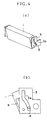
- Figures 4(a) and 4(b) show the operation panel 1 as it is being pushed as described above. Pushing the operation panel 1 toward the housing while rotating the operation panel 1 counterclockwise allows the panel to be returned to the condition in Figures 2(a) and 2(b).
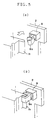
- FIG. 5(a) shows the operation panel 1 as observed immediately before the panel is installed on the front surface of the housing when the panel faces backward.
- a retainer 9a of the push lock 9 rotates counterclockwise as viewed from above.
- Pushing the operation panel 1 causes the retainer 9a of the push lock 9 to slightly move back and rotate clockwise, so that the operation panel is locked. Then releasing the locked operation panel 1 causes the retainer 9a to slightly move forward. However, the retainer keeps locking the operation panel 1, thus retaining the lib 1b of the operation panel 1 as shown in Figure 5(b), so that the operation panel 1 is kept faced backward.
- Pressing the operation panel 1 as shown in Figure 5(b) causes the retainer 9a to slightly move back and rotate counterclockwise, thus unlocking the operation panel.
- the operation panel 1 slants due to elasticity of the torsion coil spring 14 until the panel reaches the position in Figures 3(a) and 3(b).
- a push lock is commercially available which shuts when pressed and opens when repressed.
- operation panel 1 can be made to face forward as shown in Figures 2(a) and 2(b) and face backward as shown in Figures 4(a) and 4(b), starting in the condition in Figures 3(a) and 3(b).
- the above-described embodiment does not require the operation panel to be removed to prevent the panel from being stolen when it faces backward, it is not likely to lose the panel.
- the embodiment moves the operation panel to produce a wide space above the operation panel, thus complicating the path of the operation panel.
- the operation panel is manually moved, the mechanism is simplified, and a wide space is provided for recording medium insertion and discharge.
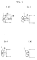
- FIG. 6 is a schematic side view showing the structure of a second embodiment, or a panel turnabout mechanism for vehicle mount audio equipment.
- a panel supporting member 15 is supported on a housing so that the member freely projects and urged in the direction of projection by a spring 18.
- the panel supporting member 15 supports the operation panel 1 so that the panel freely rotates.
- Figure 6(a) shows the operation panel 1 as installed on the front surface of the housing when the panel faces forward.
- the operation panel 1 is locked by a lock mechanism, not shown.
- the lock mechanism is unlocked, the panel supporting member 15 is pushed out due to elasticity of the spring 18 as shown in Figure 6(b).
- the operation panel 1 can manually be faced backward as shown in Figure 6(c). After faced backward, the operation panel 1 can manually be pushed in to install the operation panel 1 on the front surface of the housing when the panel faces backward.
- the operation panel 1 is also locked by a lock mechanism, not shown.
- Figure 7 shows a third embodiment of the present invention, or a panel turnabout mechanism for vehicle mount audio equipment.
- a panel supporting member 16 is supported on a housing so that the member freely rotates about an axis.
- the member supports the operation panel 1 so that it freely rotates.
- Figure 7(a) shows how audio equipment is used.
- the operation panel 1 is installed on the front surface of a housing when the panel faces forward. In this state, the operation panel 1 is locked by a lock mechanism, not shown.
- the operation panel 1 When the lock mechanism is unlocked, the operation panel 1 is rotated due to elasticity of a spring, not shown, so that the panel moves away from the front of the housing as shown in Figure 7(b). After the operation panel 1 is rotated 180° in a direction A in the figure together with the panel supporting member 16, rotating the operation panel 1 toward the front of the housing allows the operation panel 1 to be installed on the front surface of the housing when the panel faces backward as shown in Figure 7(c). The operation panel 1 is also locked by a lock mechanism, not shown.
- the above-described embodiment does not require the operation panel to be removed to prevent the panel from being stolen when it faces backward, it is not likely to lose the panel. Because the operation panel is manually moved, the mechanism is simplified, and a wide space is provided for recording medium insertion and discharge.
- An operation panel turnabout mechanism for vehicle mount audio equipment of the present invention allows two types of operation panels on the back of which a display is provided to be used. If an operation panel whose back is blank is used, the panel can be made to face backward without removing it, thus preventing it from being stolen, so that it is not likely to lose the panel.
- the operation panel is manually moved, no motor is needed, the mechanism is simplified, and its manufacturing cost is reduced. Moreover, because of the simple mechanism, a narrower space is needed, and the equipment is reduced in weight.
Landscapes
- Engineering & Computer Science (AREA)
- Computer Networks & Wireless Communication (AREA)
- Signal Processing (AREA)
- Multimedia (AREA)
- Fittings On The Vehicle Exterior For Carrying Loads, And Devices For Holding Or Mounting Articles (AREA)
- Casings For Electric Apparatus (AREA)
Abstract
Description
Claims (3)
- An operation panel turnabout mechanism for vehicle mount audio equipment, characterized in that a panel supporting member which rotatably supports an operation panel is provided to freely project from a housing and urged in the direction of projection using elasticity of a spring, the operation panel is manually made to face backward with the panel supporting member being projected from the housing, and the panel supporting member is moved back against elasticity of the spring to allow the operation panel to be installed on the front surface of the housing when the operation panel faces backward.
- The operation panel turnabout mechanism for vehicle mount audio equipment according to claim 1, characterized in that the mechanism is configured so that the panel supporting member projects from the housing by rotation, and that a convexity provided in the operation panel is guided along a guide slit provided in the housing or a member secured to the housing.
- An operation panel turnabout mechanism for vehicle mount audio equipment, characterized in that an operation panel supporting member which rotatably supports an operation panel is rotatably supported on a housing, the operation panel is rotated in such a direction that the panel moves away from the housing, the operation panel supporting member is manually rotated to face the operation panel backward, and then the operation panel is rotated toward the housing to allow the operation panel to be installed on the front surface of the housing when the operation panel faces backward.
Applications Claiming Priority (3)
| Application Number | Priority Date | Filing Date | Title |
|---|---|---|---|
| JP18275299A JP3477551B2 (en) | 1999-06-29 | 1999-06-29 | Operation panel reversing mechanism for in-vehicle audio equipment |
| JP18275299 | 1999-06-29 | ||
| PCT/JP2000/004314 WO2001000451A1 (en) | 1999-06-29 | 2000-06-29 | Operation panel reversing mechanism for on-vehicle sound equipment |
Publications (2)
| Publication Number | Publication Date |
|---|---|
| EP1108617A1 true EP1108617A1 (en) | 2001-06-20 |
| EP1108617A4 EP1108617A4 (en) | 2008-09-03 |
Family
ID=16123825
Family Applications (1)
| Application Number | Title | Priority Date | Filing Date |
|---|---|---|---|
| EP00940892A Withdrawn EP1108617A4 (en) | 1999-06-29 | 2000-06-29 | Operation panel reversing mechanism for on-vehicle sound equipment |
Country Status (5)
| Country | Link |
|---|---|
| US (1) | US6659405B1 (en) |
| EP (1) | EP1108617A4 (en) |
| JP (1) | JP3477551B2 (en) |
| DE (1) | DE1108617T1 (en) |
| WO (1) | WO2001000451A1 (en) |
Cited By (3)
| Publication number | Priority date | Publication date | Assignee | Title |
|---|---|---|---|---|
| EP1236617A1 (en) * | 2001-02-17 | 2002-09-04 | Dr.Ing. h.c.F. Porsche Aktiengesellschaft | Display Unit for a Vehicle |
| GB2379074A (en) * | 2001-08-09 | 2003-02-26 | Bosch Gmbh Robert | Driver's information device |
| GB2410120A (en) * | 2004-01-13 | 2005-07-20 | Giga Byte Tech Co Ltd | Multi-media player having a rotatable panel that can be restored automatically |
Families Citing this family (10)
| Publication number | Priority date | Publication date | Assignee | Title |
|---|---|---|---|---|
| JP4251765B2 (en) * | 2000-10-03 | 2009-04-08 | アルパイン株式会社 | Automotive electronics |
| JP2002254991A (en) * | 2001-03-01 | 2002-09-11 | Kenwood Corp | Case with front panel and on-vehicle acoustic device |
| US20020162932A1 (en) * | 2001-05-04 | 2002-11-07 | Poorman Richard N. | Accessory mounting bracket |
| US7568663B2 (en) * | 2002-09-10 | 2009-08-04 | Kabushiki Kaisha Kenwood | Electronic apparatus |
| US7356954B2 (en) * | 2003-12-01 | 2008-04-15 | Fujitsu Ten Limited | In-vehicle display apparatus |
| JP4092505B2 (en) * | 2004-06-10 | 2008-05-28 | 日産自動車株式会社 | Cockpit module mounting structure |
| US7543871B2 (en) * | 2006-12-22 | 2009-06-09 | Chrysler Llc | Center console |
| JP2016210266A (en) | 2015-05-07 | 2016-12-15 | パナソニックIpマネジメント株式会社 | Panel opening/closing device |
| CN109343400A (en) * | 2018-10-22 | 2019-02-15 | 广东浪庭电器科技有限公司 | A kind of circuit control panel of open air intelligent sound |
| US20220097618A1 (en) * | 2020-09-30 | 2022-03-31 | Nissan North America, Inc. | Vehicular Electronics Module Installation and Removal |
Family Cites Families (12)
| Publication number | Priority date | Publication date | Assignee | Title |
|---|---|---|---|---|
| JPH06103874B2 (en) | 1992-04-13 | 1994-12-14 | 三井金属鉱業株式会社 | Correlation circuit unit for spread spectrum signal reception |
| JPH0629947U (en) * | 1992-09-28 | 1994-04-19 | 株式会社ケンウッド | In-vehicle electronic device panel device |
| JP3322781B2 (en) * | 1995-10-30 | 2002-09-09 | 株式会社ケンウッド | Automotive electronics |
| JP3274964B2 (en) * | 1996-03-29 | 2002-04-15 | 株式会社ケンウッド | Automotive electronics |
| JP3348211B2 (en) * | 1996-07-04 | 2002-11-20 | 株式会社ケンウッド | Electronics |
| JP3172683B2 (en) * | 1996-10-09 | 2001-06-04 | 株式会社ケンウッド | Automotive electronics |
| JPH10313179A (en) * | 1997-05-14 | 1998-11-24 | Alpine Electron Inc | Front panel opening/closing mechanism of car-borne equipment |
| DE69916669T2 (en) * | 1998-01-07 | 2005-04-28 | Clarion Co., Ltd. | Vehicle-mounted record carrier reproducing apparatus |
| JPH11213646A (en) * | 1998-01-20 | 1999-08-06 | Kenwood Corp | On-vehicle electronic apparatus |
| JP3568185B2 (en) * | 1998-02-10 | 2004-09-22 | 株式会社ケンウッド | Operation panel drive mechanism for in-vehicle electronic devices |
| US6474431B1 (en) * | 2000-06-30 | 2002-11-05 | Caterpillar Inc | Rotatable instrument panel assembly |
| JP2002254991A (en) * | 2001-03-01 | 2002-09-11 | Kenwood Corp | Case with front panel and on-vehicle acoustic device |
-
1999
- 1999-06-29 JP JP18275299A patent/JP3477551B2/en not_active Expired - Fee Related
-
2000
- 2000-06-29 DE DE1108617T patent/DE1108617T1/en active Pending
- 2000-06-29 US US09/763,874 patent/US6659405B1/en not_active Expired - Fee Related
- 2000-06-29 WO PCT/JP2000/004314 patent/WO2001000451A1/en not_active Ceased
- 2000-06-29 EP EP00940892A patent/EP1108617A4/en not_active Withdrawn
Cited By (5)
| Publication number | Priority date | Publication date | Assignee | Title |
|---|---|---|---|---|
| EP1236617A1 (en) * | 2001-02-17 | 2002-09-04 | Dr.Ing. h.c.F. Porsche Aktiengesellschaft | Display Unit for a Vehicle |
| GB2379074A (en) * | 2001-08-09 | 2003-02-26 | Bosch Gmbh Robert | Driver's information device |
| GB2379074B (en) * | 2001-08-09 | 2003-08-06 | Bosch Gmbh Robert | Driver's information device |
| GB2410120A (en) * | 2004-01-13 | 2005-07-20 | Giga Byte Tech Co Ltd | Multi-media player having a rotatable panel that can be restored automatically |
| GB2410120B (en) * | 2004-01-13 | 2006-01-18 | Giga Byte Tech Co Ltd | Multi-media player having a rotatable panel that can be restored automatically |
Also Published As
| Publication number | Publication date |
|---|---|
| DE1108617T1 (en) | 2002-02-21 |
| JP2001010414A (en) | 2001-01-16 |
| EP1108617A4 (en) | 2008-09-03 |
| JP3477551B2 (en) | 2003-12-10 |
| WO2001000451A1 (en) | 2001-01-04 |
| US6659405B1 (en) | 2003-12-09 |
Similar Documents
| Publication | Publication Date | Title |
|---|---|---|
| US6659405B1 (en) | Operation panel reversing mechanism for on-vehicle sound equipment | |
| US5185804A (en) | Operating device of an electronic equipment mounted on a motor vehicle | |
| EP1550582A1 (en) | Electronic apparatus | |
| JP3227329B2 (en) | Anti-theft device for in-vehicle electronic devices | |
| JP3172683B2 (en) | Automotive electronics | |
| JP3268476B2 (en) | Panel attachment / detachment mechanism | |
| JP3322781B2 (en) | Automotive electronics | |
| JP3001794B2 (en) | In-vehicle display device | |
| JP3274964B2 (en) | Automotive electronics | |
| JP3353271B2 (en) | Automotive electronics | |
| JPH09246735A (en) | Panel opener | |
| JP2021020666A (en) | Bracket for on-vehicle equipment and holding device for on-vehicle equipment | |
| JP3186966B2 (en) | In-vehicle audio-visual equipment | |
| JP3938268B2 (en) | Electronics | |
| JP3095987B2 (en) | In-vehicle display device | |
| JPH0939675A (en) | In-vehicle display device | |
| JP3568185B2 (en) | Operation panel drive mechanism for in-vehicle electronic devices | |
| JP2777526B2 (en) | In-vehicle display device | |
| JP2576053Y2 (en) | Power transmission mechanism | |
| JPH11213646A (en) | On-vehicle electronic apparatus | |
| JP2806371B2 (en) | Head carriage lock mechanism | |
| JPH0939674A (en) | On-vehicle display device | |
| JPH11126466A (en) | Mechanism of attaching/detaching tiltable control panel for on-vehicle acoustic equipment | |
| JPH0737986Y2 (en) | Vehicle storage device | |
| JPH11123991A (en) | Electronic equipment mounting device |
Legal Events
| Date | Code | Title | Description |
|---|---|---|---|
| PUAI | Public reference made under article 153(3) epc to a published international application that has entered the european phase |
Free format text: ORIGINAL CODE: 0009012 |
|
| 17P | Request for examination filed |
Effective date: 20010226 |
|
| AK | Designated contracting states |
Kind code of ref document: A1 Designated state(s): AT BE CH CY DE DK ES FI FR GB GR IE IT LI LU MC NL PT SE |
|
| EL | Fr: translation of claims filed | ||
| DET | De: translation of patent claims | ||
| RBV | Designated contracting states (corrected) |
Designated state(s): DE FR GB |
|
| A4 | Supplementary search report drawn up and despatched |
Effective date: 20080804 |
|
| RAP1 | Party data changed (applicant data changed or rights of an application transferred) |
Owner name: KABUSHIKI KAISHA KENWOOD |
|
| 17Q | First examination report despatched |
Effective date: 20090422 |
|
| RAP1 | Party data changed (applicant data changed or rights of an application transferred) |
Owner name: JVC KENWOOD CORPORATION |
|
| STAA | Information on the status of an ep patent application or granted ep patent |
Free format text: STATUS: THE APPLICATION HAS BEEN WITHDRAWN |
|
| 18W | Application withdrawn |
Effective date: 20130718 |