EP1108567A1 - Pneumatic tire - Google Patents
Pneumatic tire Download PDFInfo
- Publication number
- EP1108567A1 EP1108567A1 EP00913070A EP00913070A EP1108567A1 EP 1108567 A1 EP1108567 A1 EP 1108567A1 EP 00913070 A EP00913070 A EP 00913070A EP 00913070 A EP00913070 A EP 00913070A EP 1108567 A1 EP1108567 A1 EP 1108567A1
- Authority
- EP
- European Patent Office
- Prior art keywords
- tyre
- point
- centre
- line
- axial direction
- Prior art date
- Legal status (The legal status is an assumption and is not a legal conclusion. Google has not performed a legal analysis and makes no representation as to the accuracy of the status listed.)
- Granted
Links
Images


Classifications
-
- B—PERFORMING OPERATIONS; TRANSPORTING
- B60—VEHICLES IN GENERAL
- B60C—VEHICLE TYRES; TYRE INFLATION; TYRE CHANGING; CONNECTING VALVES TO INFLATABLE ELASTIC BODIES IN GENERAL; DEVICES OR ARRANGEMENTS RELATED TO TYRES
- B60C17/00—Tyres characterised by means enabling restricted operation in damaged or deflated condition; Accessories therefor
-
- B—PERFORMING OPERATIONS; TRANSPORTING
- B60—VEHICLES IN GENERAL
- B60C—VEHICLE TYRES; TYRE INFLATION; TYRE CHANGING; CONNECTING VALVES TO INFLATABLE ELASTIC BODIES IN GENERAL; DEVICES OR ARRANGEMENTS RELATED TO TYRES
- B60C3/00—Tyres characterised by the transverse section
- B60C3/04—Tyres characterised by the transverse section characterised by the relative dimensions of the section, e.g. low profile
-
- B—PERFORMING OPERATIONS; TRANSPORTING
- B60—VEHICLES IN GENERAL
- B60C—VEHICLE TYRES; TYRE INFLATION; TYRE CHANGING; CONNECTING VALVES TO INFLATABLE ELASTIC BODIES IN GENERAL; DEVICES OR ARRANGEMENTS RELATED TO TYRES
- B60C9/00—Reinforcements or ply arrangement of pneumatic tyres
- B60C9/02—Carcasses
- B60C9/0292—Carcass ply curvature
Definitions
- the present invention relates to a pneumatic tyre in which run-flat performance can be improved while suppressing increase of tyre weight.
- the desire is growing for a tyre on which a driver can drive a car by himself/herself to the nearest gas station or automobile repair shop when a tyre deflation has occurred while running such that the driver does not have to replace the tyre at a road shoulder on an express way at midnight, in bad weather, or the like.
- the rigidity of the whole tyre is normally increased so as to improve durability.
- the number of plies of the carcass that is the framework of the tyre is increased or the thickness of rubber is increased, for example. Because these means have been embodied substantially empirically, the weight of the tyre has been increased by a large amount.
- the present invention has been accomplished with the above circumstances in view and it is an object of the present invention to provide a pneumatic tyre in which run-flat performance as continuous travelling performance after deflation can be improved based on considering a model of stress analysis of a tyre and improving the sectional shape of the tyre to obtain an optimal sectional shape by which maximum stress applied to the tyre can be reduced while minimising increase in tyre weight.
- a pneumatic tyre comprising a carcass extending from a tread portion through sidewall portions to bead cores in bead portions and satisfying the following expressions (1) to (4): Ra/D ⁇ 0.08 Rb/D ⁇ 0.08 0 ⁇ a ⁇ 50° and 0 ⁇ b ⁇ 50° where, in a tyre meridional section in a standard state in which the tyre is mounted on a standard wheel rim, inflated to standard inner pressure, and not loaded, Ra is a radius of curvature of a first arc having a centre Oa on a tyre axial direction line X passing through a midpoint between a first point A and a second point B and on a tyre inner cavity side and in contact with a tyre centre line at the first point A, the first point A being a point where a tyre radial direction line Y passing through a wheel rim width position of the standard wheel rim intersects
- each the sidewall portion on the tyre axial direction line X is 0.008 to 0.022 times the outer diameter D of the tyre.
- a pneumatic tyre comprising a carcass extending from a tread portion through sidewall portions to bead cores in bead portions, wherein a tyre section constant J per a unit circumferential length defined by the following expression (9) is 0.8 or smaller: where, in a tyre meridional section in a standard state in which the tyre is mounted on a standard wheel rim, inflated to standard inner pressure, and not loaded, Ra is a radius of curvature of a first arc having a centre Oa on a tyre axial direction line X passing through a midpoint between a first point A and a second point B and on a tyre inner cavity side and in contact with a tyre centre line at the first point A, the first point A being a point where a tyre radial direction line Y passing through a wheel rim width position of the standard wheel rim intersects the tyre centre
- the thickness h of each the sidewall portion on the tyre axial direction line X is 0.01 to 0.022 times an outer diameter D of the tyre in the' standard state and that an arc coefficient C of the tyre defined by the following expression (10) is 5.0 or smaller:
- the distance H in the radial direction of the tyre is preferably 0.085 times the outer diameter D of the tyre in the standard state or smaller.
- FIG. 1 shows a tyre meridional section including a tyre axis of a pneumatic tyre 1 of the present embodiment and shows a radial tyre of a tubeless type (205/55R15) for passenger cars including a carcass 6 extending from a tread portion 2 through sidewall portions 3 to bead cores 5 in bead portions 4 and a belt layer 7 disposed on a radially outside of the tyre of the carcass 6 and having an inner liner rubber on a tyre inner cavity face i as an example.
- a tyre meridional section including a tyre axis of a pneumatic tyre 1 of the present embodiment and shows a radial tyre of a tubeless type (205/55R15) for passenger cars including a carcass 6 extending from a tread portion 2 through sidewall portions 3 to bead cores 5 in bead portions 4 and a belt layer 7 disposed on a radi
- the tyre is illustrated as an assembly formed of the tyre and a wheel rim in a standard state in which the tyre is mounted on a standard wheel rim J, inflated to standard inner pressure (180kPa), and not loaded and the tyre section width SW is 223.0 mm and the tyre section height TH is 112.0 mm.
- the "standard wheel rim” is a wheel rim specified for each tyre by a standard in a standard system including the standard on which the tyre is based and is a normal wheel rim when specified by JATMA, a design rim by TRA, and a measuring rim by ETRTO, for example.
- the "standard inner pressure” is air pressure specified for each tyre by each standard in a standard system including a standard on which the tyre is based and is defined as the highest air pressure when specified by JATMA, the maximum value in a table "TYRE LOAD LIMITS AT VARIOUS COLD INFLATION PRESSURES" by TRA, and inflation pressure by ETRTO.
- the "standard inner pressure” is 180 kPa uniformly.
- the carcass 6 is formed of one or more (one, in this example) carcass plies 6A with a radial structure formed by arranging the carcass cords at angles in a range of 75° to 90° with respect to the tyre equator C.
- the carcass cords organic fibre cords of nylon, rayon, polyester, and the like can be used.
- the carcass ply 6A having a main portion 6a extending from the tread portion 2 through the sidewall portions 3 to the bead cores 5 in the bead portions 4 and turned-up portions 6b extending from the main portions 6a and turned up around the bead cores 5 is shown as an example.
- bead apexes 10 extending outward in a radial direction of the tyre from the bead cores 5 and made of hard rubber are disposed to reinforce the bead portions 4.
- the tyre including wheel rim protectors 4a extending to cover outsides in the radial direction of the tyre of rim flanges JF at the bead portions 4 is shown as an example.
- the belt layer 7 is formed by placing at least two (inner and outer two, in this example) belt plies 7A and 7B with one on the other.
- Each the belt ply is formed of cords arranged at small angles of 15 to 40°, for example, with respect to the tyre equator.
- the belt piles 7A and 7B are placed such that the cords are in directions crossing each other.
- steel cords are used as the belt cords in this example, organic fibre cords with high elasticity such as aramid and rayon can be also used if necessary.
- a band layer arranged at an angle of 5° or smaller with respect to the tyre equator C may be provided on an outside in the radial direction of the tyre of the belt layer 7.
- rubber reinforcing layers having substantially crescent sectional shapes are not provided to inner faces of the sidewall portions 3 in the present embodiment, it is possible to provide the rubber reinforcing layers to further reinforce the sidewall portions 3 and to set the hardness and coefficient of elasticity of the rubber disposed at the sidewall portions 3 so as to improve the run-flat performance.
- FIG. 2 shows an outline of a tyre meridional section (right half portion) including a tyre axis in a standard state of the pneumatic tyre 1.
- a tyre centre line CL passing through a centre of a thickness of the tyre is shown by a one-dot dashed line.
- the "tyre centre line” is specified based on the outline (shown by a dotted line) of the bead portion 4 that does not include patterns on a tyre outer surface and the projection of the wheel rim protector 4a formed at the bead portion 4, i.e., excluding the wheel rim protector 4a in this example.
- a first point where a tyre radial direction line Y passing through a wheel rim width position (an inner face position of the wheel rim flange JF) of the standard wheel rim J intersects the tyre centre line CL on a tread portion 2 side is defined as A and a second point where the tyre radial direction line Y intersects the tyre centre line CL on a bead portion 4 side is defined as B.
- a radius of curvature of a first arc Ca having a centre Oa on a tyre axial direction line X passing through a midpoint between the first point A and the second point B and on a tyre inner cavity side and in contact with the tyre centre line CL at the first point A is defined as Ra and a radius of curvature of a second arc Cb having a centre Ob on the tyre axial direction line X and on the tyre inner cavity side and in contact with the tyre centre line CL at the second point B is defined as Rb.
- the centres Oa and Ob of the respective arcs Ca and Cb can be determined respectively as points where normals perpendicular to tangents to the tyre cenbre line CL at the first point A and the second point B intersect the tyre axial direction line X.
- An intersection point P of the tyre centre line CL and the tyre axial direction line X on an outside in the tyre axial direction of the arcs Ca and Cb on the tyre axial direction line X is shown as an example.
- an angle formed by the tyre axial direction line X and a straight line Oa-A connecting the centre Oa and the first point A is defined as ⁇ a (deg) and an angle formed by the tyre axial direction line X and a straight line Ob-B connecting the centre Ob and the second point B is defined as ⁇ b (deg).
- D an outer diameter of the tyre in a standard state
- the pneumatic tyre 1 is characterised in that it satisfies the following expressions (1) to (4).
- Ra and D are of the same unit).
- FIG. 6(B) that is a sectional view taken along a line Z-Z in FIG. 6(A)
- h represents a thickness of the beam in the section Z-Z
- b represents the width
- the radius R of curvature of the curved beam and its central angle ⁇ + should be reduced to reduce the maximum stress ⁇ m without increasing the thickness h of the beam. If this is applied to the tyre, the radius R of curvature and the central angle ⁇ of the curved beam respectively correspond to a radius of curvature and its central angle of ,the sidewall portion 3 of the tyre. Therefore, by controlling the radius of curvature and the central angle (sectional height) of the sidewall portion 3 of the tyre so as to reduce them, the maximum stress would be reduced without increasing the rubber thickness of the tyre, and so for example, durability would be improved, and a continuous travelling distance after deflation can be increased.
- the radius Ra of curvature of the first arc Ca and the radius Rb of curvature of the second arc Cb may be the same as each other or may be different from each other.
- ⁇ a and ⁇ b may be the same as each other or may be different from each other.
- the inventors made a considerable number of tyres by way of test.
- the outline shapes of the sidewall portions 3 were varied to obtain varying radiuses Ra, Rb of curvature and varying central angles ⁇ a and ⁇ b and the inventors studied the continuous travelling distances after deflation of the tyres.
- limiting the shape of the tyre to satisfy the above expressions (1) to (4) regardless of the tyre size and the like was shown to be particularly preferable so as to improve durability in run-flat travelling.
- Ra/D is generally set at a value greater than 0.08 and a value of this ratio Ra/D (or Rb/D) is set at a value smaller than that in prior-art in the present invention.
- Z h 2 /6
- h is a thickness of the sidewall portion on the tyre axial direction line X and unit of Ra, Rb, D, and h is (mm).
- FIG. 3 shows a graph of a result obtained by making the tyres with varying tyre constant T by way of test and testing the run-flat performance of each the tyre.
- the run-flat performance was obtained by mounting each of the tyres in two sizes, 215/45ZR17 and 205/55R15 on a wheel rim with an inner pressure of 0kPa, mounting it on the front right side of a domestically produced passenger car, causing the car to travel a test course, testing a continuous travelling distance travelled by the tyre running deflated until the tyre could no longer be used for travelling, and making it an index.
- the test course included a straight portion and a corner portion and the test was conducted on the same condition that the travelling speed in the straight portion was 50km/H and that the travelling speed in the corner portion was 40km/H.
- the test was conducted while the thickness h of the sidewall portion on the tyre axial direction line X of every tyre was set at 13 mm.
- the run-flat performance tended to reduce as the tyre constant T increased.
- the run-flat performance was found to be kept at a satisfactorily high level by setting the tyre constant T at 1.6 ⁇ 10 -3 or smaller and it was more desirable to set the tyre constant T at 1.0 ⁇ 10 -3 or smaller and still more desirable at 0.6 ⁇ 10 -3 or smaller.
- a lower limit of the tyre constant T is preferably set at 0.4 ⁇ 10 -3 , for example.
- FIG. 4 shows a relationship between the thickness h of the sidewall portion 3 on the tyre axial direction line X and tyre weight (index) of one tyre. If the thickness h of the sidewall portion is too small, absolute rigidity of the sidewall portion 3 tends to reduce. Therefore, it is desirable to set the thickness h at 5 mm or greater and more desirable at 8 mm or greater. If the thickness h of the sidewall portion 3 is too large, the tyre weight tends to increase considerably. Therefore, the thickness h is preferably set at 13 mm or smaller, for example.
- the concrete thickness is preferably set such that a ratio (h/D) between the thickness h and the tyre outer diameter D is about 0.008 to 0.022.
- the above expression (8) is multiplied by Z to eliminate an element of the thickness h of the sidewall portion, expressed by a parameter, a curvature constant V of the tyre so as to test an influence of a sectional shape of the sidewall portion 3, and defined by the following expression (6).
- Setting the curvature constant V of the tyre at 10 ⁇ 10 -3 or smaller was found to be preferable.
- V (Ra/D) ⁇ 1-cos( ⁇ a/2) ⁇ +(Rb/D) ⁇ 1-cos( ⁇ b/2) ⁇
- FIG. 5 shows the result of testing the run-flat performance when the curvature constant V of the tyre was varied.
- the run-flat performance was tested by a test similar to the above test.
- the run-flat performance tends to reduce as the curvature constant V of the tyre increases.
- the run-flat performance can be kept at a satisfactorily high level by setting the curvature constant V of the tyre at 10.0 ⁇ 10 -3 or smaller and it is more desirable to set the constant V at 9.0 ⁇ 10 -3 or smaller and still more desirable at 8.0 ⁇ 10 -3 or smaller.
- a lower limit of the curvature constant V is preferably set at 6.0 ⁇ 10 -3 , for example.
- Table 1 shows an example of the respective values Ra, Rb, ⁇ a, ⁇ b, h, T, and V.
- tyres A, B, tyres C, D, tyres E, F with the varying thickness h of the sidewall portion 3 are compared with each other, the tyre constant T is reduced by increasing h, and it can be seen from FIG. 3 that the run-flat performance is improved. If the tyres A and C, for example, with the same thickness h of the sidewall portion 3 are compared with each other, the smaller Ra and Rb are, the more the tyre constant T can be reduced. Furthermore, if the tyres A and E, for example, with the same thickness h of the sidewall portion 3 are compared with each other, the smaller ⁇ a and ⁇ b are, the more the tyre constant T can be reduced.
- a first point where a tyre radial direction line Y passing through a wheel rim width position (an inner face position of the wheel rim flange JF) of the standard wheel rim J intersects a tyre centre line CL on a tread portion 2 side is defined as A and a second point where the tyre radial direction line Y intersects the tyre centre line CL on a bead portion 4 side is defined as B.
- a radius of curvature of a first arc Ca having a centre Oa on a tyre axial direction line X passing through a midpoint between the first point A and the second point B and on a tyre inner cavity side and in contact with the tyre centre line CL at the first point A is defined as Ra and a radius of curvature of a second arc Cb having a centre Ob on the tyre axial direction line X and on the tyre inner cavity side and in contact with the tyre centre line CL at the second point B is defined as Rb.
- a distance in the tyre radial direction from the first point A to the second point B is defined as H.
- a tyre section constant J per a unit circumferential length defined by the following expression (9) is set at 0.8 or smaller.
- Z h 2 /6 and h is the thickness of the sidewall portion on the tyre axial direction line X.
- the unit of Ra, Rb, H, and h is (mm).
- H' a distance between points of application of the loads W, W is defined as H'
- H' the distance between points of application of the loads W, W is defined as H'
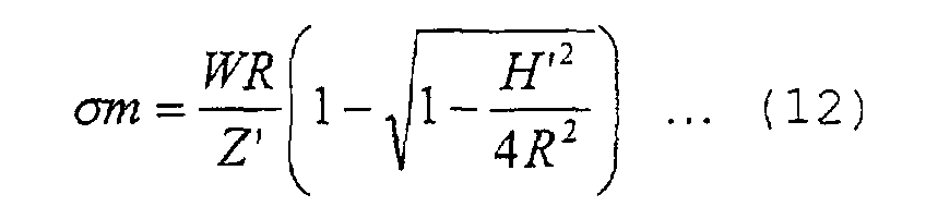
- the maximum stress ⁇ m in the section Z-Z can be expressed by an expression (12).
- the maximum stress ⁇ m can be obtained as the sum of respective maximum stresses ⁇ mb and ⁇ ma on inner and outer sides of the tyre axial direction line X.
- the radius R of curvature of the curved beam can be approximately applied to the radiuses Ra and Rb of the tyre.
- H' of the curved beam can be applied as a half of the distance H in the radial direction of the tyre between the first point A and the second point B of the sidewall portion 3 of the tyre. Therefore, the expression (12) can be applied to the pneumatic tyre in a phantom manner as the following expression (13).
- Z represents a sectional coefficient "h 2 /6" of the sidewall portion per a unit circumferential length and h represents a thickness of the sidewall portion on the tyre axial direction line X.
- This expression (13) approximately expresses the maximum stress ⁇ m applied to the Z-Z section of the sidewall portion 3 of the pneumatic tyre with respect to a certain load W. What is obtained by dividing this expression by the load W is expressed by a parameter, a tyre section constant J per a unit circumferential length in the present specification and is defined by the above expression (9).
- the inventors made a considerable number of tyres by way of test outline shapes of the sidewall portions 3 of which were varied to obtain varying radiuses Ra, Rb of curvature and varying distance H in the radius direction of the tyre and studied the continuous travelling distances after deflation of the tyres.
- limiting the tyre section constant J defined by the above expression (9) was found to be particularly preferable so as to improve durability in the run-flat travelling.
- FIG. 7 shows a graph of a result obtained by making the tyres with varying tyre section constant J by way of test and testing the run-flat performance of each the tyre.
- the run-flat performance was measured on the same condition as before.
- the run-flat performance tended to reduce as the tyre section constant J increased.
- the run-flat performance was found to be kept at a satisfactorily high level by setting the tyre section constant J at 0.8 or smaller and it is more desirable to set the tyre section constant J at 0.7 or smaller, still more desirable at a value 0.5 or smaller, and yet more desirable at 0.1 to 0.5.
- the tyre section constant J is generally set at a value greater than 0.8 and particularly at 1.0 or greater in many cases.
- the radiuses Ra and Rb of curvature and the distance H such that the tyre section constant J can be reduced as compared with prior art, it is possible to reduce the maximum stress applied to the sidewall portion 3 as compared with prior art without increasing the thickness of the sidewall portion 3, for example.
- durability of the tyre can be improved and the continuous travelling distance after deflation can be increased.
- influence of the sectional shape of the sidewall portion 3 was tested by using a parameter, an arc coefficient C (defined by the above expression (10)) of the tyre obtained by multiplying the above expression (9) by "Z" to eliminate an element of the thickness h of the sidewall portion 3 of the tyre.
- Setting the arc coefficient C of the tyre at 5.0 or smaller was found to be preferable (unit of Ra, Rb, and H is mm).
- FIG. 8 shows the result of testing of the run-flat performance when the arc coefficient C of the tyre was varied.
- the run-flat performance was tested by a test similar to the above test. As is clear from FIG. 8, the run-flat performance tended to reduce as the arc coefficient C of the tyre increased. However, the run-flat performance could be kept at an allowable high level by settings the arc coefficient C at 5.0 or smaller and it was more desirable to set the arc coefficient C at 4.0 or smaller and more desirable at 2.5 to 4.0.
- FIG. 9 shows a graph with the arc coefficient C plotted on a vertical axis and the tyre section constant J on a horizontal axis.
- the run-flat performance (index) and the thickness h of the sidewall portion on the tyre axial direction line X of each the tyre to be tested are plotted.
- the tyre that satisfies both J ⁇ 0.8 and C ⁇ 5.0 had remarkably satisfactory run-flat performance.
- FIG. 4 shows a relationship between the thickness h of the sidewall portion 3 on the tyre axial direction line X and the tyre weight (index) of one tyre.
- the thickness h of the sidewall portion 3 is set at 13 mm or smaller, for example, so as to prevent significant increase of the tyre weight and particularly to obtain a weight increase of 110% or less. Therefore, in the present embodiment, it is also preferable to set the thickness h of the sidewall portion 3 at 6.13 to 13mm.
- Such a specific thickness is set such that a ratio (h/D) between the thickness h and the tyre outer diameter D is about 0.01 to 0.022.
- FIG. 10 shows a model of a long column that receives a load in an axial direction.
- Pk n ⁇ 2 ⁇ E ⁇ A/(L/k) 2
- FIG. 11 shows a result obtained by testing the run-flat performance while varying the distance H.
- a ratio (H/D) obtained by dividing the distance H by the outer diameter D of the tyre in the standard state so as to eliminate the influence of the tyre size is plotted in a horizontal axis.
- the run-flat performance was tested by a test similar to the above test. The thickness h of the sidewall portion of every tyre was set at 13 mm. From FIG. 11, it can be seen that the run-flat performance tends to reduce as the distance H of the tyre increases. However, the run-flat performance was found to be kept at a high level by setting the ratio (H/D) at 0.85 or smaller and it is more desirable to set the ratio (H/D) at 0.8 or smaller.
- the pneumatic tyre of the present invention based on controlling the outline shape of the sidewall portion in the standard state in a certain range, it is possible to reduce the maximum stress applied to the sidewall portion as compared with prior art and it is possible to improve the run-flat performance while suppressing increase of tyre weight, for example.
- Pneumatic tyres of tyre size of 215/45R16 and shown in Table 2 were made (Embodiments 1 to 4) and the run-flat performance, tyre weight, rolling resistance, and the like were measured.
- tyres not of the present invention were also made and tested. Tyres of comparison examples 1 and 2 are of the same size as above and tyres of a comparison example 3 and prior-art are of a tyre size of 205/55R15.
- the tyre weight and rolling resistance were measured.
- weight of one tyre was measured and was expressed by an index in which weight of the prior art was assumed to be 100. The smaller the value is, the more desirable the weight is.
- the tyre to be tested was mounted on a standard wheel rim and inflated to an inner pressure of 180kPa and the rolling resistance value was measured by using a drum-type tyre rolling resistance tester with a drum diameter of 1707.6mm while causing the tyre to travel under a load of 275kg per a tyre at a speed of 80km/H.
- a result of evaluation ' is expressed by an index in which the rolling resistance of the prior art is assumed to be 100. The smaller the value is, the smaller the rolling resistance is.
Landscapes
- Engineering & Computer Science (AREA)
- Mechanical Engineering (AREA)
- Tires In General (AREA)
Abstract
Description
h = a thickness of each sidewall portion on the tyre axial direction line X.


| Tyre size 215/45R17 | ||||||
| Tyre A | Tyre B | Tyre C | Tyre D | Tyre E | Tyre F | |
| Ra (mm) | 48 | 48 | 45 | 45 | 48 | 48 |
| Rb (mm) | 48 | 48 | 45 | 45 | 48 | 48 |
| Ra/D | 0.08 | 0.08 | 0.075 | 0.075 | 0.08 | 0.08 |
| Rb/D | 0.08 | 0.08 | 0.075 | 0.075 | 0.08 | 0.08 |
| a (deg) | 50 | 50 | 50 | 50 | 45 | 45 |
| b (deg) | 50 | 50 | 50 | 50 | 45 | 45 |
| Distance between A and B (mm) | 73.54 | 73.54 | 68.944 | 68.944 | 67.882 | 67.882 |
| D (mm) | 600 | 600 | 600 | 600 | 600 | 600 |
| h/D (×10-3) | 21.67 | 12.50 | 21.67 | 12.17 | 21.67 | 11.33 |
| Tyre constant T (×10-3) | 0.5322 | 1.5990 | 0.4990 | 1.5823 | 0.4324 | 1.5804 |
| Curvature constant V of tyre (×10-3) | 14.991 | 14.991 | 14.054 | 14.054 | 12.179 | 12.179 |



| Embodiment 1 | Embodiment 2 | Embodiment 3 | Embodiment 4 | Comparison example 1 | Comparison example 2 | Comparison examples 3 | Prior art | |
| Ra/D | 0.063 | 0.057 | 0.071 | 0.060 | 0.053 | 0.058 | 0.080 | 0.082 |
| Rb/D | 0.063 | 0.058 | 0.058 | 0.057 | 0.060 | 0.065 | 0.105 | 0.091 |
| a(deg) | 38 | 46 | 33 | 40 | 54.5 | 50.5 | 46 | 48.5 |
| b(deg) | 40 | 46 | 42 | 43 | 48 | 45 | 33 | 44 |
| D (mm) (JATMA design dimension) | 600 | 600 | 600 | 600 | 600 | 600 | 607 | 607 |
| h(mm) | 9.5 | 8 | 10 | 9 | 6 | 4 | 14 | 6 |
| Tyre constant T (×10-3) | 0.48 | 0.66 | 0.41 | 0.56 | 1.85 | 3.95 | 0.33 | 2.31 |
| Curvature constant V of the tyre (×10-3) | 7.27 | 9.14 | 6.79 | 7.56 | 11.11 | 10.52 | 10.67 | 13.87 |
| Run-flat performance (index) | 208 | 146 | 264 | 153 | 122 | 100 | 298 | 100 |
| Tyre weight (index) | 94 | 94 | 92 | 92 | 85 | 77 | 120 | 100 |
| Rolling resistance (index) | 97 | 97 | 96 | 99 | 95 | 87 | 108 | 100 |
| h/D(×10-3) | 15.83 | 13.33 | 16.67 | 15.00 | 10.00 | 6.667 | 23.06 | 9.885 |
| Embodiment 5 | Embodiment 6 | Embodiment 7 | Embodiment 8 | Comparison example 4 | Comparison examples 5 | Comparison examples 6 | Prior art 2 | |
| Ra(mm) | 38.0 | 34.0 | 42.5 | 36.0 | 32.0 | 35.0 | 48.6 | 50.0 |
| Rb(mm) | 38.0 | 35.0 | 35.0 | 34.0 | 36.0 | 39.0 | 63.5 | 55.0 |
| H(mm) | 48 | 50 | 46 | 46.5 | 52 | 54 | 69 | 75 |
| h(mm) | 9.5 | 8 | 10 | 9 | 6 | 4 | 14 | 6 |
| D(mm) | 600 | 600 | 600 | 600 | 600 | 600 | 607 | 607 |
| H/D | 0.080 | 0.083 | 0.077 | 0.078 | 0.087 | 0.090 | 0.114 | 0.124 |
| h/D | 0.0158 | 0.0133 | 0.0167 | 0.0150 | 0.0100 | 0.0067 | 0.0231 | 0.0099 |
| Tyre section constant J | 0.26 | 0.44 | 0.21 | 0.29 | 0.86 | 1.92 | 0.17 | 1.16 |
| Tyre arc coefficient C | 3.89 | 4.69 | 3.53 | 3.98 | 5.19 | 5.12 | 5.55 | 6.94 |
| Run-flat performance (index) | 208 | 146 | 264 | 153 | 122 | 100 | 298 | 100 |
| Tyre weight (index) | 94 | 94 | 92 | 92 | 85 | 77 | 120 | 100 |
| Rolling resistance (index) | 97 | 97 | 96 | 99 | 95 | 87 | 108 | 100 |
Claims (8)
- A pneumatic tyre comprising a carcass extending from a tread portion through sidewall portions to bead cores in bead portions characterised by satisfying the following expressions (1) to (4):Rb is a radius of curvature of a second arc having a centre Ob on said tyre axial direction line X and on said tyre inner cavity side and in contact with said tyre centre line at said second point B,a is an angle formed by said tyre axial direction line X and a straight line Oa-A connecting said centre Oa and said first point A,b is an angle formed by said tyre axial direction line X and a straight line Ob-B connecting said centre Ob and said second point B, andD is an outer diameter of said tyre in said standard state.
- A pneumatic tyre according to claim 1, characterised by a tyre constant T defined by the following expression (5) is 1.6×10⁻³ or smaller:
h is a thickness of each said sidewall portion on said tyre axial direction line X. - A pneumatic tyre according to claim 2, characterised in that said thickness h of each said sidewall portion on said tyre axial direction line X is 0.008 to 0.022 times said outer diameter D of said tyre.
- A pneumatic tyre according to any one of claims 1 to 3, characterised in that a tyre curvature constant V defined by the following expression (6) is 10×10-3 or smaller:
- A pneumatic tyre comprising a carcass extending from a tread portion through sidewall portions to bead cores in bead portions, characterised in that a tyre section constant J per a unit circumferential length defined by the following expression (9) is 0.8 or smaller:where, in a tyre meridional section in a standard state in which said tyre is mounted on a standard wheel rim, inflated to a standard inner pressure, and not loaded, Ra is a radius of curvature of a first arc having a centre Oa on a tyre axial direction line X passing through a midpoint between a first point A and a second point B and on a tyre inner cavity side and in contact with a tyre centre line at said first point A, said first point A being a point where a tyre radial direction line Y passing through a wheel rim width position of said standard wheel rim intersects said tyre centre line passing through a midpoint of a thickness of said tyre on a tread portion side and a second point B being a point where said tyre radial direction line Y intersects said tyre centre line on a bead portion side,
 Rb is a radius of curvature of a second arc having a centre Ob on said tyre axial direction line X and on said tyre inner cavity side and in contact with said tyre centre line at said second point B,H is a distance in a radial direction of said tyre from said first point A to said second point B,Z=h2/6, andh is a thickness of each said sidewall portion on said tyre axial direction line X.
 - A pneumatic tyre according to claim 5, characterised in that said thickness h of each said sidewall portion on said tyre axial direction line X is 0.01 to 0.022 times an outer diameter D of said tyre in said standard state.
- A pneumatic tyre according to claim 5 or 6, characterised in that an arc coefficient C of said tyre defined by the following expression (10) is 5.0 or smaller:

- A pneumatic tyre according to any one of claims 5 to 7, characterised in that said distance H in said radial direction of said tyre is 0.085 times said outer diameter D of said tyre in said standard state or smaller.
Applications Claiming Priority (5)
| Application Number | Priority Date | Filing Date | Title |
|---|---|---|---|
| JP9661199 | 1999-04-02 | ||
| JP09661199A JP3455693B2 (en) | 1999-04-02 | 1999-04-02 | Pneumatic tire |
| JP9661299 | 1999-04-02 | ||
| JP09661299A JP3455694B2 (en) | 1999-04-02 | 1999-04-02 | Pneumatic tire |
| PCT/JP2000/002134 WO2000059741A1 (en) | 1999-04-02 | 2000-03-31 | Pneumatic tire |
Publications (3)
| Publication Number | Publication Date |
|---|---|
| EP1108567A1 true EP1108567A1 (en) | 2001-06-20 |
| EP1108567A4 EP1108567A4 (en) | 2002-02-13 |
| EP1108567B1 EP1108567B1 (en) | 2006-11-29 |
Family
ID=26437787
Family Applications (1)
| Application Number | Title | Priority Date | Filing Date |
|---|---|---|---|
| EP00913070A Expired - Lifetime EP1108567B1 (en) | 1999-04-02 | 2000-03-31 | Pneumatic tire |
Country Status (4)
| Country | Link |
|---|---|
| US (2) | US6457503B1 (en) |
| EP (1) | EP1108567B1 (en) |
| DE (1) | DE60032103T2 (en) |
| WO (1) | WO2000059741A1 (en) |
Cited By (1)
| Publication number | Priority date | Publication date | Assignee | Title |
|---|---|---|---|---|
| EP2960076A4 (en) * | 2013-02-20 | 2016-11-02 | Bridgestone Corp | Pneumatic tire |
Families Citing this family (3)
| Publication number | Priority date | Publication date | Assignee | Title |
|---|---|---|---|---|
| JP5410038B2 (en) * | 2007-12-17 | 2014-02-05 | 株式会社ブリヂストン | Pneumatic tire |
| JP6853772B2 (en) * | 2017-12-20 | 2021-03-31 | 株式会社ブリヂストン | Pneumatic radial tires for aircraft |
| CN112288820B (en) * | 2020-12-29 | 2021-04-27 | 深圳市六合智能感知系统科技有限公司 | Contour calculation method, device and equipment for regular object and storage medium |
Family Cites Families (7)
| Publication number | Priority date | Publication date | Assignee | Title |
|---|---|---|---|---|
| JPH02147417A (en) * | 1988-11-30 | 1990-06-06 | Sumitomo Rubber Ind Ltd | Pneumatic safety tire |
| JPH0415111A (en) | 1990-05-07 | 1992-01-20 | Sumitomo Rubber Ind Ltd | Safety tire |
| US5388626A (en) * | 1991-06-17 | 1995-02-14 | Sumitomo Rubber Industries, Ltd. | Radial tire |
| US5427166A (en) * | 1994-01-18 | 1995-06-27 | Michelin Recherche Et Technique S.A. | Run-flat tire with three carcass layers |
| JP3064225B2 (en) | 1995-12-15 | 2000-07-12 | 住友ゴム工業株式会社 | Pneumatic tire for run flat |
| DE19707090A1 (en) * | 1997-02-24 | 1998-08-27 | Continental Ag | Pneumatic vehicle wheel |
| JP4015280B2 (en) | 1998-05-28 | 2007-11-28 | 住友ゴム工業株式会社 | Tire and rim assembly |
-
2000
- 2000-03-31 DE DE60032103T patent/DE60032103T2/en not_active Expired - Fee Related
- 2000-03-31 EP EP00913070A patent/EP1108567B1/en not_active Expired - Lifetime
- 2000-03-31 WO PCT/JP2000/002134 patent/WO2000059741A1/en not_active Ceased
- 2000-03-31 US US09/700,914 patent/US6457503B1/en not_active Expired - Fee Related
-
2002
- 2002-07-30 US US10/207,060 patent/US6651714B2/en not_active Expired - Fee Related
Cited By (1)
| Publication number | Priority date | Publication date | Assignee | Title |
|---|---|---|---|---|
| EP2960076A4 (en) * | 2013-02-20 | 2016-11-02 | Bridgestone Corp | Pneumatic tire |
Also Published As
| Publication number | Publication date |
|---|---|
| US6651714B2 (en) | 2003-11-25 |
| DE60032103D1 (en) | 2007-01-11 |
| EP1108567A4 (en) | 2002-02-13 |
| WO2000059741A1 (en) | 2000-10-12 |
| EP1108567B1 (en) | 2006-11-29 |
| US6457503B1 (en) | 2002-10-01 |
| DE60032103T2 (en) | 2007-04-12 |
| US20030051789A1 (en) | 2003-03-20 |
Similar Documents
| Publication | Publication Date | Title |
|---|---|---|
| US6237661B1 (en) | Run-flat tire with specified profile | |
| US9150051B2 (en) | Pneumatic tire | |
| US7036541B2 (en) | Pneumatic tire | |
| EP2112004B1 (en) | Pneumatic tire | |
| EP1867497A1 (en) | Run-flat tire | |
| US20080006359A1 (en) | Runflat tire | |
| US11254167B2 (en) | Pneumatic tyre | |
| US10870318B2 (en) | Pneumatic tire | |
| JPWO2002042094A1 (en) | Pneumatic safety tire | |
| US5871601A (en) | Pneumatic radial tire with load bearing rubber reinforcing layer | |
| GB2198996A (en) | Radial tyres | |
| EP1022162A1 (en) | Tire with improved run-flat design | |
| EP0393965B1 (en) | Pneumatic radial tires having improved running performances | |
| JP2001121917A (en) | Pneumatic radial tire | |
| EP1108567B1 (en) | Pneumatic tire | |
| JP3455693B2 (en) | Pneumatic tire | |
| EP1182060A2 (en) | Pneumatic tire | |
| EP3943660B1 (en) | Tire | |
| JPH11334315A (en) | Tire and rim assembly | |
| US20180244113A1 (en) | Run flat tire and method for manufacturing same | |
| JP3455694B2 (en) | Pneumatic tire | |
| US11667155B2 (en) | Pneumatic tire for heavy duty | |
| EP4410569A1 (en) | Pneumatic tire | |
| EP1013477B1 (en) | Pneumatic tyre | |
| JP2002528336A (en) | 2-ply run flat tire with reinforced tread |
Legal Events
| Date | Code | Title | Description |
|---|---|---|---|
| PUAI | Public reference made under article 153(3) epc to a published international application that has entered the european phase |
Free format text: ORIGINAL CODE: 0009012 |
|
| 17P | Request for examination filed |
Effective date: 20001130 |
|
| AK | Designated contracting states |
Kind code of ref document: A1 Designated state(s): DE FR GB |
|
| A4 | Supplementary search report drawn up and despatched |
Effective date: 20020102 |
|
| AK | Designated contracting states |
Kind code of ref document: A4 Designated state(s): DE FR GB |
|
| RIC1 | Information provided on ipc code assigned before grant |
Free format text: 7B 60C 17/00 A, 7B 60C 13/00 B, 7B 60C 3/04 B |
|
| GRAP | Despatch of communication of intention to grant a patent |
Free format text: ORIGINAL CODE: EPIDOSNIGR1 |
|
| GRAS | Grant fee paid |
Free format text: ORIGINAL CODE: EPIDOSNIGR3 |
|
| GRAA | (expected) grant |
Free format text: ORIGINAL CODE: 0009210 |
|
| AK | Designated contracting states |
Kind code of ref document: B1 Designated state(s): DE FR GB |
|
| REG | Reference to a national code |
Ref country code: GB Ref legal event code: FG4D |
|
| REF | Corresponds to: |
Ref document number: 60032103 Country of ref document: DE Date of ref document: 20070111 Kind code of ref document: P |
|
| PGFP | Annual fee paid to national office [announced via postgrant information from national office to epo] |
Ref country code: GB Payment date: 20070322 Year of fee payment: 8 |
|
| PGFP | Annual fee paid to national office [announced via postgrant information from national office to epo] |
Ref country code: DE Payment date: 20070531 Year of fee payment: 8 |
|
| ET | Fr: translation filed | ||
| PLBE | No opposition filed within time limit |
Free format text: ORIGINAL CODE: 0009261 |
|
| STAA | Information on the status of an ep patent application or granted ep patent |
Free format text: STATUS: NO OPPOSITION FILED WITHIN TIME LIMIT |
|
| 26N | No opposition filed |
Effective date: 20070830 |
|
| PGFP | Annual fee paid to national office [announced via postgrant information from national office to epo] |
Ref country code: FR Payment date: 20070319 Year of fee payment: 8 |
|
| GBPC | Gb: european patent ceased through non-payment of renewal fee |
Effective date: 20080331 |
|
| REG | Reference to a national code |
Ref country code: FR Ref legal event code: ST Effective date: 20081125 |
|
| PG25 | Lapsed in a contracting state [announced via postgrant information from national office to epo] |
Ref country code: DE Free format text: LAPSE BECAUSE OF NON-PAYMENT OF DUE FEES Effective date: 20081001 |
|
| PG25 | Lapsed in a contracting state [announced via postgrant information from national office to epo] |
Ref country code: FR Free format text: LAPSE BECAUSE OF NON-PAYMENT OF DUE FEES Effective date: 20080331 |
|
| PG25 | Lapsed in a contracting state [announced via postgrant information from national office to epo] |
Ref country code: GB Free format text: LAPSE BECAUSE OF NON-PAYMENT OF DUE FEES Effective date: 20080331 |