EP1108555A2 - Recording apparatus - Google Patents
Recording apparatus Download PDFInfo
- Publication number
- EP1108555A2 EP1108555A2 EP00127601A EP00127601A EP1108555A2 EP 1108555 A2 EP1108555 A2 EP 1108555A2 EP 00127601 A EP00127601 A EP 00127601A EP 00127601 A EP00127601 A EP 00127601A EP 1108555 A2 EP1108555 A2 EP 1108555A2
- Authority
- EP
- European Patent Office
- Prior art keywords
- roller
- friction surface
- low
- recording apparatus
- recording
- Prior art date
- Legal status (The legal status is an assumption and is not a legal conclusion. Google has not performed a legal analysis and makes no representation as to the accuracy of the status listed.)
- Granted
Links
Images



Classifications
-
- B—PERFORMING OPERATIONS; TRANSPORTING
- B65—CONVEYING; PACKING; STORING; HANDLING THIN OR FILAMENTARY MATERIAL
- B65H—HANDLING THIN OR FILAMENTARY MATERIAL, e.g. SHEETS, WEBS, CABLES
- B65H5/00—Feeding articles separated from piles; Feeding articles to machines
- B65H5/06—Feeding articles separated from piles; Feeding articles to machines by rollers or balls, e.g. between rollers
- B65H5/062—Feeding articles separated from piles; Feeding articles to machines by rollers or balls, e.g. between rollers between rollers or balls
-
- B—PERFORMING OPERATIONS; TRANSPORTING
- B41—PRINTING; LINING MACHINES; TYPEWRITERS; STAMPS
- B41J—TYPEWRITERS; SELECTIVE PRINTING MECHANISMS, i.e. MECHANISMS PRINTING OTHERWISE THAN FROM A FORME; CORRECTION OF TYPOGRAPHICAL ERRORS
- B41J13/00—Devices or arrangements of selective printing mechanisms, e.g. ink-jet printers or thermal printers, specially adapted for supporting or handling copy material in short lengths, e.g. sheets
- B41J13/0072—Handling wide cut sheets, e.g. using means for enabling or facilitating the conveyance of wide sheets
-
- B—PERFORMING OPERATIONS; TRANSPORTING
- B41—PRINTING; LINING MACHINES; TYPEWRITERS; STAMPS
- B41J—TYPEWRITERS; SELECTIVE PRINTING MECHANISMS, i.e. MECHANISMS PRINTING OTHERWISE THAN FROM A FORME; CORRECTION OF TYPOGRAPHICAL ERRORS
- B41J13/00—Devices or arrangements of selective printing mechanisms, e.g. ink-jet printers or thermal printers, specially adapted for supporting or handling copy material in short lengths, e.g. sheets
- B41J13/02—Rollers
-
- B—PERFORMING OPERATIONS; TRANSPORTING
- B65—CONVEYING; PACKING; STORING; HANDLING THIN OR FILAMENTARY MATERIAL
- B65H—HANDLING THIN OR FILAMENTARY MATERIAL, e.g. SHEETS, WEBS, CABLES
- B65H2404/00—Parts for transporting or guiding the handled material
- B65H2404/10—Rollers
- B65H2404/14—Roller pairs
-
- B—PERFORMING OPERATIONS; TRANSPORTING
- B65—CONVEYING; PACKING; STORING; HANDLING THIN OR FILAMENTARY MATERIAL
- B65H—HANDLING THIN OR FILAMENTARY MATERIAL, e.g. SHEETS, WEBS, CABLES
- B65H2404/00—Parts for transporting or guiding the handled material
- B65H2404/50—Surface of the elements in contact with the forwarded or guided material
- B65H2404/53—Surface of the elements in contact with the forwarded or guided material with particular mechanical, physical properties
- B65H2404/531—Surface of the elements in contact with the forwarded or guided material with particular mechanical, physical properties particular coefficient of friction
Definitions
- the present invention relates to a recording apparatus capable of recording on recording paper with a paper width of almost size A1 or B1 at the maximum and, more particularly, relates to a recording apparatus including a transport roller structure which is suitable for ensuring the stable transport of the paper at a center supporting portion which supports a long transport roller for transporting the recording paper at the center portion thereof to thereby suppress the occurrence of cockling phenomenon.
- a paper feeding section is disposed at the upper portion in the rear of the main body of the recording apparatus, recording paper is fed toward the front portion of the recording apparatus from the paper feeding section and transported to a recording section by way of a slanted paper transport path, then the paper subjected to the recording process is ejected in the slanted downward direction from a paper ejecting section, and the paper thus ejected is received by a receiving unit provided at the lower portion of the recording apparatus.
- the recording paper in the form of a paper in which paper is wound on a core, or a cut sheet is fed to the recording section and the recording is conducted by a recording head which is mounted on a carriage and moves reciprocally.
- a paper feeding section is constituted by a transport roller driven and rotated by a motor and a driven roller which rotates in accordance with the rotation of the transport roller.
- the paper feeding section is disposed near the recording head and arranged in a manner that the driven roller acts to press the recording paper against the transport roller thereby to transport the recording paper toward the recording area where the recording head exists.
- a large-sized recording apparatus accorded to the wide recording paper requires a long transport roller corresponding to the width of the recording paper, so that a paper feeding section thereof employs the structure that many driven rollers are disposed in parallel to the long transport roller.
- a spring member is provided at every driven roller so that a predetermined urging force is uniformly applied to the entire width of the recording paper to thereby push the recording paper against the transport roller.
- Such a long transport roller bends at the center portion thereof due to various reasons.
- the transport rollers bend slightly due to mechanical allowance or tolerance.
- the transport roller bends at its center portion due to its own weight.
- the degree of the flexure of the transport roller differs depending on that the roller is formed as a tubular member or a pillar member.
- the roller has such a nature that the thicker the wall thickness becomes, the less the roller bends.
- Such a bending phenomenon of the transport roller degrades the transporting accuracy of the recording paper and results in the degradation of the recording quality thereof.
- As a countermeasure for such a phenomenon when the diameter of the transport roller is made large to such a degree for preventing the bending of the roller caused by its own weight, there arises such a problem that a larger space for disposing such a transport roller is required and the size of a bearing portion also becomes large. Accordingly, such a transport roller with a large diameter is not practical.
- the transport roller since the transport roller is applied with pressure (load) from the driven rollers, the transport roller also bends due to this pressure.
- the latter amount is larger than the former amount.
- a bending amount becomes larger due to the multiplier effect of these bending phenomena, and this bending amount becomes larger as the length of the transport roller becomes longer and the diameter of the transport roller becomes smaller, so that the transporting accuracy of the recording paper is further influenced.
- an object of the invention is to provide a recording apparatus which can suppress the unstable transporting operation of papers at the center supporting portion of a transport roller and also suppress the generation of origin of cockling phenomenon.
- a recording apparatus comprising:
- a force for gripping the paper surely acts on the paper and so the paper can be transported stably even though the transport roller is provided with the low-friction surface which diameter is slightly smaller than that of the high-friction surface.
- the recording paper running between the driven roller and the low-friction surface of the transport roller is restricted in its position by the surface of the driven roller in a state that the surface of the driven roller extends over the low-friction surface and the high-friction surface at the boundary portions between the low-friction surface and.
- the high-friction surface and the elastically-deformed driven roller almost eliminates the gap with respect to the low-friction surface, so that the generation of origin of the cockling phenomenon at the low-friction surface portion can be suppressed.
- the supporting member is arranged so as to oppose to the second roller through the first roller.
- the roller surface of the second roller extends so as to oppose to an entire width of the first portion of the first roller.
- the surface of the driven roller is disposed in opposite to the entire width of the low-friction surface of the transport roller, the transporting stability of the recording paper which is transported while opposing to the low-friction surface can be further improved. Further, the generation of origin of the cockling phenomenon can be suppressed not only at the low-friction surface portion but over the entire width of the low-friction surface.
- the roller surface of the second roller extends so as to oppose to a part of the first portion of the first roller.
- the roller surface of the second roller opposes to both widthwise end portion of the first portion of the first roller.
- the second roller includes a plurality of individual rollers respective widths of which are identical with each other.
- the manufacturing cost of the apparatus can be reduced and the management cost also can be reduced due to the decrease of the number of kind of components.
- the second roller includes a plurality of individual driven rollers.
- a widthwise dimension of the individual driven roller opposing to the entire width of the first portion of the first roller is larger than another individual driven rollers.
- the surface of the second portion of the first roller is defined by a coating layer.
- the friction coefficient of the roller capable of obtaining high transporting accuracy can be fabricated easily.
- a thickness of the coating layer is within a range of 15 ⁇ m to 100 ⁇ m.
- the roller having efficiency suited to the. specification of the recording apparatus can be obtained by selecting the thickness of the coating layer.
- the difference between the first diameter and the second diameter is twice of the thickness of the coating layer.
- the second portion of the first roller is arranged in both sides portion of the first portion thereof, and urged by the second roller.
- the embodiment relates to a large sized recording apparatus capable of recording on recording paper with a paper width of almost size A1 or B1 at the maximum, to which the invention is applied.
- the recording apparatus 1 is formed by a paper feeding section 2, a recording section 3 and a paper ejecting section 4.
- the paper feeding section 2 is provided at the rear upper portion of the recording apparatus 1 so as to protrude upward.
- a roll-shaped recording paper 20 is set within the paper feeding section and a paper cover 21 is attached to the paper feeding section to cover the recording paper 20 so as to be able to open and close freely.
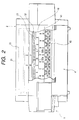
- the recording section 3 includes a carriage 30 having a recording head 31 mounted thereon, a transport roller 32 and driven rollers 33 which transports the recording paper 20 in the sub-scanning direction, an ink supplying unit for supplying ink to the recording head 31, a paper suction unit which sucks the open air from a suction opening 41 provided at a paper transport path 40 to suck the recording paper 20 to thereby prevent the recording paper from floating, and a control unit for executing the recording procedure etc.
- the recording section is provided with a top cover 36 and a front cover 37 so as to cover the carriage 30, a flat cable 34, ink tubes 35, the paper transport path and so on.
- the front cover 37 is rotatably supported at its lower portion positioned on the paper transport surface side.
- the carriage 30 is suspended through a roller from a rail 7 which is supported at its both ends by a side frame 39, and also coupled to a carriage belt 6.
- the belt 6 is operated by a carriage driver (not shown)
- the carriage 30 links with the movement of the carriage belt 6 and is guided by the rail 7 to thereby move reciprocally therealong.
- the recording head 31 is coupled to the flat cable 34 for sending a recording signal from the control unit to the recording head and also coupled to the ink tubes 35 for supplying ink to the recording head.
- the recording section 3 is provided at its front side with a cartridge holder 5 constituting the ink supplying device.
- a holder body 50 of the cartridge holder 5 accommodates ink cartridges 52 of six colors (yellow, light magenta, light cyan, magenta, cyan and black) in a manner that these ink cartridges are disposed side by side and so as to be able to be detachably inserted from the front side.
- the holder body 50 is provided with a holder cover 51 which is arranged to cover the inserted ink cartridges 52 and so as to be able to be closed and opened.
- the ink of the respective colors are supplied to the recording head 31 through the ink tube 35 and used for the recording on the recording paper 20.
- the recording operation of the recording apparatus 1 of this embodiment is performed in the following manner. That is, the recording paper 20 fed from the paper feeding section 2 is intermittently sent to a platen 48 side by the cooperative operation of the transport roller 32 and the driven roller 33, then the recording operation on the recording paper is performed by the reciprocal operation of the recording head 31, and the recording paper 20 thus recorded is ejected in the slanted downward direction from the recording apparatus 1 by an ejection roller 42 in the paper ejecting section 4.
- a cutter (not shown) for cutting the recording paper 20 is provided between the recording section 3 and the paper ejecting section 4 so that, after the completion of the recording operation, the recording paper is cut by the cutter and ejected.
- Fig. 4 is a plan view which is viewed from a line I-I in Fig. 2 and Fig. 5 is a section view taken along a line II-II in Fig. 4.
- the transport roller 32 has high rigidity and is pivotally supported at its both ends by the bearing portion (not shown) of the side frame 39.
- the transport roller 32 is. arranged in a manner that the surface thereof supported by a center supporting member 38 is formed as a low-friction surface 32a and the surface thereof except for the low-friction surface 32a is formed as a high-friction surface 32b whose diameter is made slightly larger than that of the low-friction surface 32a.
- the high-friction surface 32b is formed by the known ceramic coating process in which ceramic particles such as silicon carbide is dispersed uniformly.
- the low-friction surface 32a is formed by the polish finishing process, for example.
- the diameter of the high-friction surface 32b is made slightly larger than that of the low-friction surface 32a.
- the degree of the slightly large diameter means the degree sufficient for defining the low-friction surface.
- the diameter of the high-friction surface is made larger than that of the low-friction surface by almost the thickness of the ceramic coating.
- the diameter difference between the high-friction surface and the low-friction surface may be slightly smaller or larger than the thickness of the ceramic coating.
- the thickness of the coating forming the high-friction surface 32b is in a range of 15 ⁇ m to 100 ⁇ m. In view of the fact that the friction coefficient of the surface of the transport roller 32 is too small when the coating film is less than 15 ⁇ m and that the coating film becomes weak when the coating film is too thick, the thickness of the coating film is preferably about 30 ⁇ m.
- a gap (shown by G in Fig. 4) between a lower face of a shaft of the driven roller 33 and the high-friction surface 32b is in a range of 1.5 mm to 1.7 mm, which is quite larger as compared with the thickness of the coating film of the high-friction surface 32b.
- the driven roller 33 is disposed to oppose to the high-friction surface 32b and the low-friction surface 32a in a manner that the surface of the driven roller extends over the boundary portions 61.
- the surface of the driven roller 33 is slightly so deformed elastically as to be bent toward the low-friction surface 32a of the transport roller 32.
- the gap between the driven roller 33 and the low-friction surface 32a further reduced or almost eliminated over the entire width of the low-friction surface 32a.
- the recording paper running between the driven roller 33 and the low-friction surface 32a is restricted in a state that the paper extends over the low-friction surface 32a and the high-friction surface 32b by the surface of the driven roller 33 at the boundary portions 61 of the transport roller 32, and the elastically-deformed driven roller 33 almost eliminates the gap with respect to the low-friction surface 32a, so that the generation of origin of the cockling phenomenon at the low-friction surface 32a portion can be suppressed.
- the low-friction surface 32a of the transport roller 32 is disposed so as to oppose to the surface of the driven roller 33 having a width larger than the width w of the low-friction surface 32a.
- a rubber roller which surface is coated by fluorine, for example, is employed as the driven roller 33.
- the driven roller is always biased by a not-shown biasing member which provides pressure toward the transport roller 32.
- the difference (diameter difference) between the outer.diameter of the low-friction surface 32a and the outer diameter of the high-friction surface 32b is set to be the thickness (from 15 ⁇ m to 100 ⁇ m) of the coating forming the high-friction surface 32b, the gap between the low-friction surface 32a of the transport roller 32 and the driven roller 33 is made small and the generation of the origin of the cockling phenomenon at the low-friction surface 32a portion can be suppressed.
- the surfaces at the both end portions of the driven roller 33 provide pressure towards the high-friction surface 32b of the transport roller 32, so that the surface of the driven roller 33 opposing to the low-friction surface 32a of the transport roller 32 is partially and slightly so deformed elastically as to bent toward the low-friction surface 32a of the transport roller 32.
- the gap between the driven roller 33 and the low-friction surface 32a further reduced or almost eliminated over the entire width of the low-friction surface 32a.
- the paper feeding procedure is performed under such a circumference in a manner that the recording paper is pushed against the transport roller 32 by the driven roller 33, the transporting stability of the paper can not be degraded and the generation of the origin of cockling phenomenon at the low-friction surface 32a portion can be suppressed.
- the low-friction surface 32a of the transport roller 32 disposed on the opposite side of the driven roller 33 is pivotally supported by the center supporting member 38. Since the low-friction surface 32a of the transport roller 32 is rotatably supported at the center portion thereof,. the friction between the low-friction surface and the center supporting member 38 is small and hence the transport roller 32 can be rotated smoothly, and abrasion of the center supporting member 38 can be suppressed.
- the single driven roller having the length larger than the width of the low-friction surface 32a is employed as the surface of the driven roller 33 having the width larger than the width w of the low-friction surface 32a of the transport roller 32.
- the single driven roller having the length larger than the width of the low-friction surface 32a is employed as the surface of the driven roller 33 having the width larger than the width w of the low-friction surface 32a of the transport roller 32.
- such a surface of the driven roller having the width larger than the width w of the low-friction surface 32a may be formed by a plurality of the driven rollers.
- a plurality of the driven rollers may be arranged coaxially in a manner that the surfaces formed by these driven roller form a substantially continuous surface and the entire width of the continuous surface of these driven rollers exceeds the aforesaid width w if only it is satisfied the condition that the driven roller 33 is disposed to oppose to the high-friction surface 32b and the low-friction surface 32a in a manner that the surface the driven roller extends over the boundary portions 61.
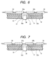
- FIG. 6 A second embodiment adopting such a configuration is shown in Fig. 6.
- the surfaces of adjacent two driven rollers 33a, 33b are disposed to oppose to a low-friction surface 32a and a high-friction surface 32b, respectively, and the two driven rollers 33a and 33b are separated to each other.
- reference numerals 51 depict the end portions of the low-friction surface 32a. In brief, it is required that the end portions 51 of the low-friction surface 32a oppose to the surfaces of the driven rollers 33.
- a length of a portion of the driven roller 33a opposing to one end portion 51 of the low-friction surface 32a is same. as a length of a portion of the driven roller 33b opposing to the other end portion 51 of the low-friction surface 32a.
- a length of a portion of the driven roller 33a opposing to one end portion 51 of the low-friction surface 32a may be arranged to differ from a length of a portion of the driven roller 33b opposing to the other end portion 51 of the low-friction surface 32a, which is a third embodiment of the present invention.
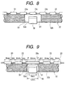
- a plurality of driven rollers 33 having the same width are provided in opposite to a transport roller 32 in a manner that the surfaces of three of these driven rollers 33a, 33b, 33c are opposed to a low-friction surface 32a, which is a fourth embodiment of the invention.
- Each of the two driven rollers 33a, 33b opposes at a part of its surface to the low-friction surface 32a, while the driven roller 33c is positioned between the two driven rollers 33a, 33b and the entire surface thereof opposes to the low-friction surface 32a.
- two or more driven rollers may be disposed between the driven rollers 33a, 33b which are disposed in an opposite manner.
- Fig. 9 shows a fifth embodiment which is a modification of the first embodiment shown in Fig. 4.
- This embodiment. is same as the first embodiment in a -point that the surface of a driven roller 33a opposing to a low-friction surface 32a is disposed so as to oppose to the entire width of the low-friction surface 32a of the transport roller 32 but differs in a point that the width of the driven roller 33a is lager than widths of other driven rollers 33 which do not oppose to the low-friction surface 32a.
- Fig. 9 shows a fifth embodiment which is a modification of the first embodiment shown in Fig. 4.
- This embodiment. is same as the first embodiment in a -point that the surface of a driven roller 33a opposing to a low-friction surface 32a is disposed so as to oppose to the entire width of the low-friction surface 32a of the transport roller 32 but differs in a point that the width of the driven roller 33a is lager than widths of other driven roller
- the with of portions of the driven roller 33a opposing to the low-friction surface 32a which is opposing to the high-friction surface 32b (in Fig. 9, the width of this portion is represented by P and so a total width of the left and right portions is 2P) can be made close to the width of the other driven rollers 33.
- the action affected on the transport roller 32 by the transport roller 32a opposing to the low-friction surface 32a becomes similar to the action affected on the transport roller 32 by the other driven rollers 33, the paper can be transported more stably.
- the total with 2Pof the portions of the driven roller 33a opposing to the low-friction surface 32a which is opposing to the high-friction surface 32b can be made equal to the width of each of the other driven rollers 33.
Landscapes
- Engineering & Computer Science (AREA)
- Mechanical Engineering (AREA)
- Delivering By Means Of Belts And Rollers (AREA)
- Electrostatic Charge, Transfer And Separation In Electrography (AREA)
- Registering, Tensioning, Guiding Webs, And Rollers Therefor (AREA)
- Handling Of Cut Paper (AREA)
- Photoreceptors In Electrophotography (AREA)
Abstract
Description
Claims (11)
- A recording apparatus comprising:a first roller arranged parallel with a main direction of a recording head for transporting a recording paper, the paper transporting roller including a first portion provided with a surface having a first friction coefficient and a first diameter, and a second portion provided with a surface having a second friction coefficient larger than the first friction coefficient and a second diameter larger than the first diameter;a second roller driven by the first roller while providing pressure to be applied onto the recording paper toward the first roller, the second roller opposed to the first roller such that a roller surface thereof extends over a boundary of the first portion and the second portion of the first roller; anda supporting member for supporting the first portion of the first roller rotatably thereon.
- The recording apparatus as set forth in claim 1, wherein the roller surface of the second roller extends so as to oppose to an entire width of the first portion of the first roller.
- The recording apparatus as set forth in claim 1, wherein the roller surface of the second roller extends so as to oppose to a part of the first portion of the first roller.
- The recording apparatus as set forth in claim 3, wherein the roller surface of the second roller opposes to both widthwise end portion of the first portion of the first roller.
- The recording apparatus as set forth in claim 1, wherein the second roller includes a plurality of individual rollers respective widths of which are identical with each other.
- The recording apparatus as set forth in claim 2, wherein the second roller includes a plurality of individual driven rollers; and
wherein a widthwise dimension of the individual driven roller opposing to the entire width of the first portion of the first roller is larger than another individual driven rollers. - The recording apparatus as set forth in claim 1, wherein the surface of the second portion of the first roller is defined by a coating layer.
- The recording apparatus as set forth in claim 7, wherein a thickness of the coating layer is within a range of 15 µm to 100 µm.
- The recording apparatus as set forth in claim 8, wherein the difference between the first diameter and the second diameter is twice of the thickness of the coating layer.
- The recording apparatus as set forth in claim 9, wherein the second portion of the first roller is arranged in both sides portion of the first portion thereof, and urged by the second roller.
- The recording apparatus as set forth in claim 1, wherein the supporting member is arranged so as to oppose to the second roller through the first roller.
Applications Claiming Priority (4)
| Application Number | Priority Date | Filing Date | Title |
|---|---|---|---|
| JP35835499 | 1999-12-17 | ||
| JP35835499 | 1999-12-17 | ||
| JP2000364740A JP3809765B2 (en) | 1999-12-17 | 2000-11-30 | Recording device |
| JP2000364740 | 2000-11-30 |
Publications (3)
| Publication Number | Publication Date |
|---|---|
| EP1108555A2 true EP1108555A2 (en) | 2001-06-20 |
| EP1108555A3 EP1108555A3 (en) | 2002-06-26 |
| EP1108555B1 EP1108555B1 (en) | 2003-07-30 |
Family
ID=26580770
Family Applications (1)
| Application Number | Title | Priority Date | Filing Date |
|---|---|---|---|
| EP00127601A Expired - Lifetime EP1108555B1 (en) | 1999-12-17 | 2000-12-15 | Recording apparatus |
Country Status (5)
| Country | Link |
|---|---|
| US (1) | US6540420B2 (en) |
| EP (1) | EP1108555B1 (en) |
| JP (1) | JP3809765B2 (en) |
| AT (1) | ATE246094T1 (en) |
| DE (1) | DE60004158T2 (en) |
Families Citing this family (11)
| Publication number | Priority date | Publication date | Assignee | Title |
|---|---|---|---|---|
| JP5338424B2 (en) * | 2009-03-25 | 2013-11-13 | セイコーエプソン株式会社 | Recording apparatus and conveying method |
| US8388094B2 (en) * | 2009-07-31 | 2013-03-05 | Zamtec Ltd | Wide format printer with input roller and movable media engagement output |
| US8485619B2 (en) | 2010-05-17 | 2013-07-16 | Zamtec Ltd | Method of priming printhead |
| TWI534015B (en) | 2010-05-17 | 2016-05-21 | 滿捷特科技公司 | System for reducing ink color mixing effects in printer |
| JP4998600B2 (en) | 2010-06-17 | 2012-08-15 | ブラザー工業株式会社 | Image recording device |
| JP2014151976A (en) * | 2013-02-05 | 2014-08-25 | Seiko Epson Corp | Medium transport device and recording apparatus |
| JP6095622B2 (en) * | 2014-09-11 | 2017-03-15 | ブラザー工業株式会社 | Image recording device |
| JP5892272B2 (en) * | 2015-02-12 | 2016-03-23 | ブラザー工業株式会社 | Image recording device |
| JP6341320B2 (en) * | 2017-06-08 | 2018-06-13 | ブラザー工業株式会社 | Image recording device |
| CN113276548B (en) * | 2020-01-31 | 2023-03-10 | 精工爱普生株式会社 | recording device |
| JP7452043B2 (en) | 2020-01-31 | 2024-03-19 | セイコーエプソン株式会社 | recording device |
Family Cites Families (9)
| Publication number | Priority date | Publication date | Assignee | Title |
|---|---|---|---|---|
| US4502804A (en) * | 1982-09-24 | 1985-03-05 | Willcox Frederick P | Paper feeding and guiding system |
| JP2751621B2 (en) * | 1990-10-31 | 1998-05-18 | ブラザー工業株式会社 | Printer |
| JP3028107B2 (en) * | 1991-04-11 | 2000-04-04 | ブラザー工業株式会社 | Printer continuous sheet switching device |
| EP0527040B1 (en) * | 1991-08-06 | 1997-01-22 | Canon Kabushiki Kaisha | Carrying roller for recording apparatus |
| JP2737492B2 (en) * | 1991-11-14 | 1998-04-08 | 日本電気株式会社 | Thermal transfer recording device |
| US5927702A (en) * | 1996-07-11 | 1999-07-27 | Canon Kabushiki Kaisha | Sheet feeder and image forming apparatus using the same |
| US6196672B1 (en) * | 1997-06-27 | 2001-03-06 | Brother Kogyo Kabushiki Kaisha | Hot-melt type ink jet printer having heating and cooling arrangement |
| EP0915050B1 (en) * | 1997-11-03 | 2002-09-04 | Gerber Scientific Products, Inc. | A web having alignment indicia and an associated web feeding and working apparatus |
| DE60028657T2 (en) * | 1999-05-14 | 2007-05-24 | Canon K.K. | Imaging device |
-
2000
- 2000-11-30 JP JP2000364740A patent/JP3809765B2/en not_active Expired - Fee Related
- 2000-12-15 DE DE60004158T patent/DE60004158T2/en not_active Expired - Lifetime
- 2000-12-15 AT AT00127601T patent/ATE246094T1/en not_active IP Right Cessation
- 2000-12-15 EP EP00127601A patent/EP1108555B1/en not_active Expired - Lifetime
- 2000-12-18 US US09/737,824 patent/US6540420B2/en not_active Expired - Lifetime
Also Published As
| Publication number | Publication date |
|---|---|
| US6540420B2 (en) | 2003-04-01 |
| DE60004158T2 (en) | 2004-04-22 |
| EP1108555B1 (en) | 2003-07-30 |
| EP1108555A3 (en) | 2002-06-26 |
| JP2001233493A (en) | 2001-08-28 |
| US20010021333A1 (en) | 2001-09-13 |
| DE60004158D1 (en) | 2003-09-04 |
| JP3809765B2 (en) | 2006-08-16 |
| ATE246094T1 (en) | 2003-08-15 |
Similar Documents
| Publication | Publication Date | Title |
|---|---|---|
| EP0838419B1 (en) | Sheet transporting device | |
| JP2945781B2 (en) | Inkjet printer | |
| US7887179B2 (en) | Inkjet recording apparatus | |
| EP1172222B1 (en) | Conveying apparatus and recording apparatus | |
| JP2001031286A (en) | Recording medium transport device | |
| EP1108555B1 (en) | Recording apparatus | |
| JP3870104B2 (en) | Paper feeding apparatus and recording apparatus provided with the same | |
| EP1798050B1 (en) | Paper roll feed mechanism and image forming apparatus | |
| US6786664B2 (en) | Active vacuum roller and method for advancing media | |
| US20020076250A1 (en) | Printer media alignment apparatus and method | |
| KR100810181B1 (en) | Sheet conveying device | |
| US6170817B1 (en) | Sheet feeding apparatus | |
| US6575459B1 (en) | Recording-medium transport device | |
| US11186459B2 (en) | Medium cutting device and image formation apparatus | |
| US6382857B1 (en) | Bearing mechanism and conveying apparatus and recording apparatus | |
| JP5219638B2 (en) | Inkjet recording device | |
| US12570098B2 (en) | Printing apparatus | |
| US11924388B2 (en) | Image recording apparatus and feed tray that includes a side guide inside a pair of sidewalls for roll paper | |
| JP2004175017A (en) | Recording medium guide mechanism and image forming apparatus provided with the mechanism | |
| US6345819B1 (en) | Paper feeding apparatus in a printer | |
| JP2000226130A (en) | Paper separation method, paper transport device, and inkjet recording device | |
| JP2002002979A (en) | Paper feeder and recording device | |
| JP2000136823A (en) | Bearing mechanism, roller holding device, transport device, and recording device | |
| JPS6260742A (en) | Sheet conveyer device for recording device | |
| JP2003118911A (en) | Sheet ejection mechanism |
Legal Events
| Date | Code | Title | Description |
|---|---|---|---|
| PUAI | Public reference made under article 153(3) epc to a published international application that has entered the european phase |
Free format text: ORIGINAL CODE: 0009012 |
|
| AK | Designated contracting states |
Kind code of ref document: A2 Designated state(s): AT BE CH CY DE DK ES FI FR GB GR IE IT LI LU MC NL PT SE TR |
|
| AX | Request for extension of the european patent |
Free format text: AL;LT;LV;MK;RO;SI |
|
| PUAL | Search report despatched |
Free format text: ORIGINAL CODE: 0009013 |
|
| AK | Designated contracting states |
Kind code of ref document: A3 Designated state(s): AT BE CH CY DE DK ES FI FR GB GR IE IT LI LU MC NL PT SE TR |
|
| AX | Request for extension of the european patent |
Free format text: AL;LT;LV;MK;RO;SI |
|
| 17P | Request for examination filed |
Effective date: 20020726 |
|
| GRAH | Despatch of communication of intention to grant a patent |
Free format text: ORIGINAL CODE: EPIDOS IGRA |
|
| AKX | Designation fees paid |
Designated state(s): AT BE CH CY DE DK ES FI FR GB GR IE IT LI LU MC NL PT SE TR |
|
| GRAH | Despatch of communication of intention to grant a patent |
Free format text: ORIGINAL CODE: EPIDOS IGRA |
|
| GRAA | (expected) grant |
Free format text: ORIGINAL CODE: 0009210 |
|
| AK | Designated contracting states |
Designated state(s): AT BE CH CY DE DK ES FI FR GB GR IE IT LI LU MC NL PT SE TR |
|
| PG25 | Lapsed in a contracting state [announced via postgrant information from national office to epo] |
Ref country code: IT Free format text: LAPSE BECAUSE OF FAILURE TO SUBMIT A TRANSLATION OF THE DESCRIPTION OR TO PAY THE FEE WITHIN THE PRESCRIBED TIME-LIMIT;WARNING: LAPSES OF ITALIAN PATENTS WITH EFFECTIVE DATE BEFORE 2007 MAY HAVE OCCURRED AT ANY TIME BEFORE 2007. THE CORRECT EFFECTIVE DATE MAY BE DIFFERENT FROM THE ONE RECORDED. Effective date: 20030730 Ref country code: FI Free format text: LAPSE BECAUSE OF FAILURE TO SUBMIT A TRANSLATION OF THE DESCRIPTION OR TO PAY THE FEE WITHIN THE PRESCRIBED TIME-LIMIT Effective date: 20030730 Ref country code: BE Free format text: LAPSE BECAUSE OF FAILURE TO SUBMIT A TRANSLATION OF THE DESCRIPTION OR TO PAY THE FEE WITHIN THE PRESCRIBED TIME-LIMIT Effective date: 20030730 Ref country code: TR Free format text: LAPSE BECAUSE OF FAILURE TO SUBMIT A TRANSLATION OF THE DESCRIPTION OR TO PAY THE FEE WITHIN THE PRESCRIBED TIME-LIMIT Effective date: 20030730 Ref country code: CH Free format text: LAPSE BECAUSE OF FAILURE TO SUBMIT A TRANSLATION OF THE DESCRIPTION OR TO PAY THE FEE WITHIN THE PRESCRIBED TIME-LIMIT Effective date: 20030730 Ref country code: NL Free format text: LAPSE BECAUSE OF FAILURE TO SUBMIT A TRANSLATION OF THE DESCRIPTION OR TO PAY THE FEE WITHIN THE PRESCRIBED TIME-LIMIT Effective date: 20030730 Ref country code: LI Free format text: LAPSE BECAUSE OF FAILURE TO SUBMIT A TRANSLATION OF THE DESCRIPTION OR TO PAY THE FEE WITHIN THE PRESCRIBED TIME-LIMIT Effective date: 20030730 Ref country code: AT Free format text: LAPSE BECAUSE OF FAILURE TO SUBMIT A TRANSLATION OF THE DESCRIPTION OR TO PAY THE FEE WITHIN THE PRESCRIBED TIME-LIMIT Effective date: 20030730 |
|
| REG | Reference to a national code |
Ref country code: GB Ref legal event code: FG4D |
|
| REG | Reference to a national code |
Ref country code: CH Ref legal event code: EP |
|
| REG | Reference to a national code |
Ref country code: IE Ref legal event code: FG4D |
|
| REF | Corresponds to: |
Ref document number: 60004158 Country of ref document: DE Date of ref document: 20030904 Kind code of ref document: P |
|
| PG25 | Lapsed in a contracting state [announced via postgrant information from national office to epo] |
Ref country code: GR Free format text: LAPSE BECAUSE OF FAILURE TO SUBMIT A TRANSLATION OF THE DESCRIPTION OR TO PAY THE FEE WITHIN THE PRESCRIBED TIME-LIMIT Effective date: 20031030 Ref country code: SE Free format text: LAPSE BECAUSE OF FAILURE TO SUBMIT A TRANSLATION OF THE DESCRIPTION OR TO PAY THE FEE WITHIN THE PRESCRIBED TIME-LIMIT Effective date: 20031030 Ref country code: DK Free format text: LAPSE BECAUSE OF FAILURE TO SUBMIT A TRANSLATION OF THE DESCRIPTION OR TO PAY THE FEE WITHIN THE PRESCRIBED TIME-LIMIT Effective date: 20031030 |
|
| PG25 | Lapsed in a contracting state [announced via postgrant information from national office to epo] |
Ref country code: ES Free format text: LAPSE BECAUSE OF FAILURE TO SUBMIT A TRANSLATION OF THE DESCRIPTION OR TO PAY THE FEE WITHIN THE PRESCRIBED TIME-LIMIT Effective date: 20031110 |
|
| NLV1 | Nl: lapsed or annulled due to failure to fulfill the requirements of art. 29p and 29m of the patents act | ||
| PG25 | Lapsed in a contracting state [announced via postgrant information from national office to epo] |
Ref country code: IE Free format text: LAPSE BECAUSE OF NON-PAYMENT OF DUE FEES Effective date: 20031215 Ref country code: LU Free format text: LAPSE BECAUSE OF NON-PAYMENT OF DUE FEES Effective date: 20031215 Ref country code: CY Free format text: LAPSE BECAUSE OF FAILURE TO SUBMIT A TRANSLATION OF THE DESCRIPTION OR TO PAY THE FEE WITHIN THE PRESCRIBED TIME-LIMIT Effective date: 20031215 |
|
| PG25 | Lapsed in a contracting state [announced via postgrant information from national office to epo] |
Ref country code: PT Free format text: LAPSE BECAUSE OF FAILURE TO SUBMIT A TRANSLATION OF THE DESCRIPTION OR TO PAY THE FEE WITHIN THE PRESCRIBED TIME-LIMIT Effective date: 20031230 |
|
| PG25 | Lapsed in a contracting state [announced via postgrant information from national office to epo] |
Ref country code: MC Free format text: LAPSE BECAUSE OF NON-PAYMENT OF DUE FEES Effective date: 20031231 |
|
| REG | Reference to a national code |
Ref country code: CH Ref legal event code: PL |
|
| ET | Fr: translation filed | ||
| PLBE | No opposition filed within time limit |
Free format text: ORIGINAL CODE: 0009261 |
|
| STAA | Information on the status of an ep patent application or granted ep patent |
Free format text: STATUS: NO OPPOSITION FILED WITHIN TIME LIMIT |
|
| 26N | No opposition filed |
Effective date: 20040504 |
|
| REG | Reference to a national code |
Ref country code: IE Ref legal event code: MM4A |
|
| REG | Reference to a national code |
Ref country code: FR Ref legal event code: PLFP Year of fee payment: 16 |
|
| REG | Reference to a national code |
Ref country code: FR Ref legal event code: PLFP Year of fee payment: 17 |
|
| REG | Reference to a national code |
Ref country code: FR Ref legal event code: PLFP Year of fee payment: 18 |
|
| PGFP | Annual fee paid to national office [announced via postgrant information from national office to epo] |
Ref country code: DE Payment date: 20171212 Year of fee payment: 18 Ref country code: FR Payment date: 20171113 Year of fee payment: 18 |
|
| PGFP | Annual fee paid to national office [announced via postgrant information from national office to epo] |
Ref country code: GB Payment date: 20171213 Year of fee payment: 18 |
|
| REG | Reference to a national code |
Ref country code: DE Ref legal event code: R119 Ref document number: 60004158 Country of ref document: DE |
|
| GBPC | Gb: european patent ceased through non-payment of renewal fee |
Effective date: 20181215 |
|
| PG25 | Lapsed in a contracting state [announced via postgrant information from national office to epo] |
Ref country code: DE Free format text: LAPSE BECAUSE OF NON-PAYMENT OF DUE FEES Effective date: 20190702 Ref country code: FR Free format text: LAPSE BECAUSE OF NON-PAYMENT OF DUE FEES Effective date: 20181231 |
|
| PG25 | Lapsed in a contracting state [announced via postgrant information from national office to epo] |
Ref country code: GB Free format text: LAPSE BECAUSE OF NON-PAYMENT OF DUE FEES Effective date: 20181215 |