EP1108476B1 - Low-pressure atomizing spray gun - Google Patents
Low-pressure atomizing spray gun Download PDFInfo
- Publication number
- EP1108476B1 EP1108476B1 EP99926841A EP99926841A EP1108476B1 EP 1108476 B1 EP1108476 B1 EP 1108476B1 EP 99926841 A EP99926841 A EP 99926841A EP 99926841 A EP99926841 A EP 99926841A EP 1108476 B1 EP1108476 B1 EP 1108476B1
- Authority
- EP
- European Patent Office
- Prior art keywords
- air
- paint
- spray gun
- paint nozzle
- nozzle
- Prior art date
- Legal status (The legal status is an assumption and is not a legal conclusion. Google has not performed a legal analysis and makes no representation as to the accuracy of the status listed.)
- Revoked
Links
- 239000007921 spray Substances 0.000 title claims description 73
- 239000003973 paint Substances 0.000 claims description 184
- 238000011144 upstream manufacturing Methods 0.000 claims description 2
- 238000000889 atomisation Methods 0.000 description 19
- 238000005507 spraying Methods 0.000 description 10
- 238000000576 coating method Methods 0.000 description 9
- 239000011248 coating agent Substances 0.000 description 7
- 238000012856 packing Methods 0.000 description 7
- 239000002245 particle Substances 0.000 description 7
- 230000007246 mechanism Effects 0.000 description 5
- 239000000203 mixture Substances 0.000 description 4
- 230000005484 gravity Effects 0.000 description 3
- 238000003915 air pollution Methods 0.000 description 2
- 238000010276 construction Methods 0.000 description 2
- 239000007788 liquid Substances 0.000 description 2
- 239000003595 mist Substances 0.000 description 2
- 230000009467 reduction Effects 0.000 description 2
- 230000000717 retained effect Effects 0.000 description 2
- 230000007480 spreading Effects 0.000 description 2
- 230000009471 action Effects 0.000 description 1
- 239000011362 coarse particle Substances 0.000 description 1
- 230000006872 improvement Effects 0.000 description 1
- 238000000034 method Methods 0.000 description 1
- 238000005457 optimization Methods 0.000 description 1
- 230000002265 prevention Effects 0.000 description 1
- 238000007789 sealing Methods 0.000 description 1
- 238000009827 uniform distribution Methods 0.000 description 1
Images






Classifications
-
- B—PERFORMING OPERATIONS; TRANSPORTING
- B05—SPRAYING OR ATOMISING IN GENERAL; APPLYING FLUENT MATERIALS TO SURFACES, IN GENERAL
- B05B—SPRAYING APPARATUS; ATOMISING APPARATUS; NOZZLES
- B05B7/00—Spraying apparatus for discharge of liquids or other fluent materials from two or more sources, e.g. of liquid and air, of powder and gas
- B05B7/02—Spray pistols; Apparatus for discharge
- B05B7/08—Spray pistols; Apparatus for discharge with separate outlet orifices, e.g. to form parallel jets, i.e. the axis of the jets being parallel, to form intersecting jets, i.e. the axis of the jets converging but not necessarily intersecting at a point
- B05B7/0807—Spray pistols; Apparatus for discharge with separate outlet orifices, e.g. to form parallel jets, i.e. the axis of the jets being parallel, to form intersecting jets, i.e. the axis of the jets converging but not necessarily intersecting at a point to form intersecting jets
- B05B7/0815—Spray pistols; Apparatus for discharge with separate outlet orifices, e.g. to form parallel jets, i.e. the axis of the jets being parallel, to form intersecting jets, i.e. the axis of the jets converging but not necessarily intersecting at a point to form intersecting jets with at least one gas jet intersecting a jet constituted by a liquid or a mixture containing a liquid for controlling the shape of the latter
-
- B—PERFORMING OPERATIONS; TRANSPORTING
- B05—SPRAYING OR ATOMISING IN GENERAL; APPLYING FLUENT MATERIALS TO SURFACES, IN GENERAL
- B05B—SPRAYING APPARATUS; ATOMISING APPARATUS; NOZZLES
- B05B7/00—Spraying apparatus for discharge of liquids or other fluent materials from two or more sources, e.g. of liquid and air, of powder and gas
- B05B7/02—Spray pistols; Apparatus for discharge
- B05B7/06—Spray pistols; Apparatus for discharge with at least one outlet orifice surrounding another approximately in the same plane
- B05B7/062—Spray pistols; Apparatus for discharge with at least one outlet orifice surrounding another approximately in the same plane with only one liquid outlet and at least one gas outlet
- B05B7/066—Spray pistols; Apparatus for discharge with at least one outlet orifice surrounding another approximately in the same plane with only one liquid outlet and at least one gas outlet with an inner liquid outlet surrounded by at least one annular gas outlet
-
- B—PERFORMING OPERATIONS; TRANSPORTING
- B05—SPRAYING OR ATOMISING IN GENERAL; APPLYING FLUENT MATERIALS TO SURFACES, IN GENERAL
- B05B—SPRAYING APPARATUS; ATOMISING APPARATUS; NOZZLES
- B05B7/00—Spraying apparatus for discharge of liquids or other fluent materials from two or more sources, e.g. of liquid and air, of powder and gas
- B05B7/02—Spray pistols; Apparatus for discharge
- B05B7/08—Spray pistols; Apparatus for discharge with separate outlet orifices, e.g. to form parallel jets, i.e. the axis of the jets being parallel, to form intersecting jets, i.e. the axis of the jets converging but not necessarily intersecting at a point
- B05B7/0807—Spray pistols; Apparatus for discharge with separate outlet orifices, e.g. to form parallel jets, i.e. the axis of the jets being parallel, to form intersecting jets, i.e. the axis of the jets converging but not necessarily intersecting at a point to form intersecting jets
- B05B7/0861—Spray pistols; Apparatus for discharge with separate outlet orifices, e.g. to form parallel jets, i.e. the axis of the jets being parallel, to form intersecting jets, i.e. the axis of the jets converging but not necessarily intersecting at a point to form intersecting jets with one single jet constituted by a liquid or a mixture containing a liquid and several gas jets
Definitions
- the present invention relates to a spray gun for atomization of a paint under a spraying air pressure of 0.07 MPa or less, and more particularly to a low-pressure air spray gun having an improved atomization mechanism used in a non-premixing type air spray gun in which a compressed air and a paint are mixed outside a spray head and which is capable of providing a spray pattern which assures an improved atomization of the paint.
- the non-mixing type air spray guns are widely used in the field of general industrial paint coating. They are defined as "spray gun” in the Japanese Industrial Standard (JIS) as well. According to the definition in JIS, the non-premixing type air spray gun is a one adapted to jet compressed air from an annular slit defined between a paint nozzle and air cap and around the paint nozzle at a high speed than the sound velocity under a specified spraying air pressure of 0.24 to 0.34 MPa and thus atomize and spray the paint to an object surface, thereby forming a paint coating on the object surface.
- This paint coating method has a widest applicability not depending upon any shape of an object surface to be coated and type of a paint used.
- the coating method is not advantageous in that much atomized paint is easily airborne or scattered and overspray causes a large loss of the paint. Because of the possible environment and air pollution by the airborne atomized paint with the conventional air spray guns, there has been a growing trend over the world to impose limitations on conditions of using the air spray gun.
- the low-pressure spray guns include some types based on different principles.
- One of the principles is to limit the spraying air pressure to less than the standard atmosphere to prevent paint particles from getting airborne or being scattered. With this spray gun, however, the limited spraying air pressure will lead to a reduced air speed, with the result that the paint atomization based on the difference in speed between gas and liquid flows, will be extremely poor.
- a low-pressure spray gun has been proposed in which the width of an air jet slit formed between a paint nozzle and air cap is increased to atomize the paint with a correspondingly increased amount of air.
- the mechanism of this low-pressure spray gun is basically the same as that of the conventional high-pressure spray guns. Namely, the air jet slit formed around the paint nozzle is designed wider to provide a larger amount of air jet even under a low pressure.
- the poor atomization of the paint due to the reduced spraying air pressure involves some problems which cannot be solved just by increasing the air amount. Namely, it has been pointed out, as such problems, that when the amount of paint flow is increased, the central portion of the paint flow will not sufficiently mix with the flow of air, resulting in an incomplete mixing, so that the paint flow in the center of the spray pattern cannot sufficiently be atomized, which is likely to take place with a paint having a slightly higher viscosity, and coarse paint particles will fly around the spray pattern when the width of the elliptic spray pattern is adjusted. That is, the reduction of the spraying air pressure will lead to a non-uniform atomization of the paint.
- the Applicant of the present invention has proposed to form a plurality of V-shaped air grooves in the tip of the paint nozzle as disclosed in his Japanese Patent Application No. 7-25907 (Japanese Unexamined Patent Publication No. 8-196950).
- Japanese Patent Application No. 7-25907 Japanese Unexamined Patent Publication No. 8-196950.
- this method was found practically not satisfactory and involves some problems to solve.
- compressed air will flow into a flow of paint yet in the paint nozzle, thereby improving the efficiency of paint atomization.
- paint and air flows will prematurely be mixed in the paint nozzle or just before the tip of the paint nozzle, the paint spray will be limited, resulting in a lower efficiency of the paint coating.
- the amount of paint spray will depend upon the pressure applied to the paint flow, independently of the pressure and amount of the compressed air jet from the aforementioned annular slit.
- the condition of jetting the compressed air to the paint delivery port will not only seriously influence the atomization but also the amount of paint spray, that is, the efficiency of coating and optimization of the spray gun itself.
- the present invention has an object to overcome the above-mentioned drawbacks of the prior art by providing a practically high efficiency spray gun.
- the present invention has a primary object to overcome the drawbacks, of the low-pressure atomization mechanism used in the conventional non-premixing type air spray gun, that atomization of a paint is partially insufficient due to a low pressure of an air flow, by providing a low-pressure atomizing spray gun including an atomization mechanism for a non-premixing type air spray gun, adapted to effectively mix low-pressure air jets, from an annular slit defined between the tip of a paint nozzle and a central opening in an air cap when the latter is fixed on the paint nozzle, with a paint flow from the paint nozzle and uniformly atomize the central portion of the pain flow, to thereby provide a uniform spray pattern without reduction in amount of the paint spray due to the attraction by the air jet.
- the present invention has another object to overcome the drawbacks of the prior art, that the sprayed paint particles easily adhere to the surface of the air cap depending upon a position where the mixed flow is diffused, the air cap surface has to be cleaned periodically and that it is necessary to prevent a paint coating once formed from being spoiled by the paint particles re-flying from the air cap surface.
- a low-pressure atomising spray gun as set out in Claim 1.
- Preferred features are set out in Claims 2 to 6.
- the compressed air is mixed with the paint flow deep to the centre of the latter, thereby permitting to atomize the paint completely and uniformly.
- the atomized paint flow is controlled against any further flying, amount of paint spray is prevented from being reduced under the action of the air inflow from the air grooves to limit the air jets, and the paint is prevented from adhering to the air cap, whereby assuring a stable spraying of the paint.
- the relatively thick air flow jet from the annular slit defined around the paint nozzle assures to uniformly atomize the paint.
- the low-pressure atomizing spray gun according to the present invention can effectively atomize the paint as with a high-pressure air spray gun, and addition of the atomization mechanism according to the present invention to the conventional low-pressure air spray gun based only on the increase of the central air flow, assures to atomize the paint with a reduced amount of air and a highly improved efficiency.
- FIG. 1 there is schematically illustrated the construction of a conventional low-pressure atomizing spray gun which will be illustrated and described by way of example herein for the better understanding of the present invention.
- the body of the spray gun is generally indicated with a reference 10.
- the spray gun body 10 includes a barrel 20 and grip 30.
- An air inlet fitting 31 is provided in the lower portion of the grip 30.
- the air inlet fitting communicates with an air passage 32. It is to be connected to a compressed air source. Compressed air supplied from the source through the air inlet fitting 31 is fed to the tip of the spray gun body 10 through an air valve chest 16 provided above the air passage 32.
- the air valve chest 16 includes an air valve seat 14, air valve 15 and packing set 19.
- the air valve chest 16 has also a coil spring 17 by which the air valve 15 is pressed to the air valve seat 14 of the air valve chest 16, whereby the air valve is sealed.
- the air valve 15 has a rod 15a extending to a trigger 13.
- a needle valve guide 5a is slid back to pull a needle valve 5 and the air valve 15 is opened slightly earlier than the needle valve 5 thus pulled, so that the compressed air will be fed slightly earlier than the paint is delivered from a paint nozzle 1.
- the needle valve guide 5a to pull the needle valve 5 linearly and also a guide chamber 23 to guide the needle valve guide 5a. Compressed air is fed around the guide chamber 23.
- the needle valve 5 is pressed by a coil spring 22 provided behind the needle valve guide 5a to the inner surface of a seat in a delivery port of the paint nozzle 1, whereby the needle valve 5 is sealed.
- the coil spring 22 is retained by a paint delivery control knob 21.
- a guide rod provided behind the needle valve guide 5a abuts the paint delivery control knob 21 to limit the sliding stroke of the needle valve 5, that is, the clearance between the seat of the delivery port 100 of the paint nozzle 1 and the needle valve 5, whereby the paint delivery can be controlled.
- a pattern divergence adjuster 24 to shunt the compressed air to the center and front end 2a of an air cap 2 and adjust the amount of air to the front end 2a.
- the pattern divergence adjuster 24 is screwed along with a pattern divergence adjusting valve 27 and pattern divergence control knob 25 to a pattern divergence adjustment guide 26.
- the pattern divergence control knob 25 By turning the pattern divergence control knob 25, the amount of compressed air to the lateral air holes 2c in the front end 2a of the air cap 2 screwed with an air cap cover 3 to the barrel 20 is adjusted in accordance with the clearance between the pattern divergence adjusting valve 27 and a valve seat 28 provided in the air passage and thus the divergence of a sector-like spray pattern is adjusted.
- a passage (not shown) of the compressed air fed from the air passage 32 formed in the grip 30 is formed in parallel to and alongside an air passage 9 provided in the seat 28 of the pattern divergence adjusting valve 27. Therefore, the air passage is branched out at the seat 28 into two of which one supplies the air to the center of the air cap 2 while the other supplies the air to the front end 2a. There is no control in the passage for the air supplied to the center of the air cap 2, and so an air pressure from the air passage 32 will be supplied at it is to the center of the air cap 2.
- FIG.2 there is illustrated in the form of a sectional view, enlarged in scale, the front end portion of the low-pressure spray gun according to the present invention.
- FIG. 2 the same or similar elements as in FIG. 1 will be indicated with the same or similar references as in FIG. 1.
- the paint nozzle 1 is screwed with a paint nozzle screw If to the barrel 20 of the spray gun body 10 and lower tapers le and 1g are connected to each other so that supply of the paint from the paint joint 8 is shut off and supply of the compressed air to the annular slit 4 and front end 2a is also shut off.
- the air cap 2 is installed to the barrel 20 with the air cap cover 3 under which a cover ring 7 is placed, to thereby cover the paint nozzle 1.
- An upper taper 1d is provided to shut off supply of the compressed air to the center and front end of the air cap as with the lower taper 1e.
- the inside of the paint nozzle 1 is sealed since an inner taper of the paint nozzle 1 is pressed by an end taper of the needle valve 5.
- the compressed air under a low pressure, shunted inside the barrel 20 and supplied through the air passage 9, is passed via a lateral air passage 2b in the front end 2a of the air cap 2 through a collar 6 and jetted out of symmetrically formed lateral air holes 2c to form an elliptic spray pattern.
- One or more lateral air hole 2c is provided in each of symmetrical positions in the front end of the air cap 2.
- the other air flow shunted inside the barrel 20 is passed from the air passage 32a to the center of the air cap 2 through a central air hole 1c formed in the paint nozzle 1.
- a central air hole 1c formed in the paint nozzle 1.
- the auxiliary air holes 2d are destined to balance the spray pattern correspondingly to the force of the air jet from the lateral air holes 2c.
- One or more such hole 2c is provided.
- the tip of the paint nozzle 1 is located in the central opening of the air cap 2 to define the annular slit 4, and the plurality of air grooves la formed in the tip of the paint nozzle 1 supplies radial air flows to the annular slit 4.
- the air grooves la are formed convergent from the outside diameter of the tip of the paint nozzle 1 towards the center of the delivery port 100 of the paint nozzle 1 and the bottom of each air groove 1 a is at the inside diameter of the paint nozzle 1.
- the angle of the convergence is within a range of 45 to 90 deg. whereby the air flows coming into the air grooves 1a collide with the paint flow from the paint nozzle so that even a low-pressure air flow can mix with the paint flow deep to the central of the latter, thus providing a complete atomization of the paint.
- the number of the air grooves 1a is not limited but when the difference (thickness) between the outside and inside diameters of the paint nozzle 1 is 0.5 to 2 times of the inside diameter, four air grooves la should suitably be provided.
- the compressed air jets from both sides are directed towards the center of the central spray flow to spread the spray perpendicularly to the compressed air.
- the air grooves should preferably be provided at 6 to 8 places.
- Each of the plurality of air grooves la is formed from a V-shaped groove 101 starting at a point 102 which is inside an inlet end 201 of the central opening of the air cap 2. See FIG. 4.
- the inlet end 201 of the central opening 200 in the air cap 2 adjoins a large angle-tapered surface 202 of the air cap 2.
- the junction of the inlet end 201 and taper surface 202 is rounded in some cases. In such a case, the compressed air flows into the central opening 200 substantially at the inlet end 201. Therefore, when the compressed air supplied into the air cap 2 flows into the central opening 200, portions thereof passing through the air grooves 1a will flow into the central hole 201 and thus effectively collide with the paint flow while increasing the area of gas-liquid contact.
- Divergently tapered guide walls 1b are provided at positions outer than the intersection of the air grooves la and inside diameter of the delivery port 100 of the paint nozzle tip.
- the angle of the divergence of the guide walls 1b is about 90 deg.
- the guide wall 1b extends from the delivery hole 100 to near the outside diameter of the paint nozzle tip to guide the paint flow at the same angle for a divergently wide spreading. Thus the paint flow will crossingly collide with the air flow jet from the annular slit 4.
- the starting points 102 of the plurality of air grooves 1a are positioned at or upstream of the inlet end 201 of the center hole 200 of the air cap 2, so that the compressed air under a relatively low pressure can cut into the paint flow deep to the center of the latter and disperse the paint, thereby assuring an improved atomization of the paint.
- the air grooves 1a extends to the inside diameter of the delivery hole 100 of the paint nozzle 1 and the guide walls 1b extend divergently in a conical form forward from the other end of the delivery hole 100, the paint flows colliding with each other and thus dispersed inside the delivery hole 100 of the paint nozzle 1 can be prevented from being diffused more than necessary and hence the paint flow can positively collide with the compressed air jet from the annular slit 4 and be atomized with a higher efficiency.
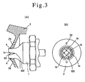
- FIG. 4A is an explanatory drawing, enlarged in scale, of the paint nozzle front end portion
- FIG. 4B is a projection view of the paint nozzle front end portion from the delivery port.
- FIG. 4A is a sectional view taken along the line A-O-B in FIG. 5B.
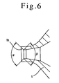
- FIG. 6 is an explanatory drawing, enlarged in scale, of the tip of the paint nozzle 1.
- the air grooves 1a each being a V-shaped one opened at an angle ⁇ of more than 45 deg. are formed to extend towards the center of the paint nozzle 1.
- the divergent angle ⁇ of the V-shaped groove is 90 deg. to which however the present invention is not limited.
- the reason why the air groove 1 a is formed as a V-shaped one is that the paint flow has to be split by the air flow directed to the center of the paint flow.
- the radius of curvature of the groove bottom should be smaller than the inside diameter of the delivery hole 100 of the paint nozzle 1, and preferably be smaller than a half of the inside diameter.
- the conical guide walls 1b are provided at the front end of the air grooves 1a.
- the guide wall 1b is divergent at an angle ⁇ . As shown, this angle ⁇ of the guide walls 1b is within 90 deg. since the guide walls 1b extend in a cylindrical form from the delivery hole 100 of the paint nozzle 1. Namely, the divergently conical spreading of the guide walls 1b makes more effective the paint atomization by the crossing collision of the paint flow with the compressed air jetted forward.
- the compressed air will mix with the point flow deep to the center of the latter and the paint will be dispersed.
- the thus dispersed and diverged flow of paint particles is controlled by the guide walls 1b in the flowing direction of the paint flow, the compressed air flow layer supplied from the annular slit 4 around the paint nozzle 1 and having a relatively large thickness will atomize the paint flow uniformly deep to the center of the latter.
- the paint will be atomized with a uniform distribution of the paint particles and a high efficiency.
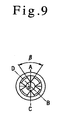
- FIGS. 7 and 8 show the flows of paint from the paint nozzle 1 and compressed air jet from the annular slit 4, and FIG. 9 is a projection view of the paint nozzle from the delivery port 100 in the paint nozzle 1.
- FIG. 7 is a sectional view taken along the line D-O-B in FIG. 9, and FIG. 8 is a sectional view taken along the line A-O-C in FIG. 9.
- the white arrow indicates the air flow while the black arrow indicates the paint flow.
- both the air flow from the annular slit 4 and those from the air grooves 1a around the paint nozzle 1 will cut into die paint flow deep to the center of the latter and contribute to the paint atomization.
- the air flows from the air grooves 1a can effectively cut into the paint flow.
- air grooves 1a V-shaped
- such air grooves if applied, in the conventional gravity type or suction type spray gun will limit the delivery of the compressed air, leading to a reduced delivery of paint spray.
- the convergent angle ⁇ of the air grooves 1a should desirably be as small as possible within a range of about 45 to 90 deg., and the geometrical relation between the paint nozzle 1 and air cap 2 is such that the tip of the paint nozzle 1 projects 0.3 to 0.8 mm from the central opening of the air cap 2.
- the starting point of the V-shaped groove 101 of the air groove 1a is located beyond the central opening 200 of the air cap 2, the paint flow will not effectively be atomized.
- a smaller the convergent angle ⁇ of the V-shaped groove 101 will provide a longer guiding by the groove, namely, a more effective delivery of compressed air and will reduce the influence of the air grooves on the delivery of paint spray. Also, by projecting the tip of the paint nozzle 1 forward from the front end of the air cap 2, it is possible to effectively prevent the delivered paint particles from adhering to the air cap 2.
- the present invention provides a low-pressure atomization spray gun with which a paint flow under a pressure of less than 0.07 MPa can be atomized, the paint mist can be prevented from being easily airborne and the paint can be sprayed with an improved efficiency. Therefore, the spray gun according to the present invention can overcome the drawbacks such as mist scattering and loss of the paint due to an overspray with the non-premixing type air spray gun and will contribute very much to the improvement of working environment and prevention of air pollution.
Landscapes
- Nozzles (AREA)
Description
Claims (6)
- A low-pressure atomising spray gun including an air spray gun body (10), a paint nozzle (1) screwed to the spray gun body (10), and an air cap (2) installed with a cover (3) thereof in the spray gun body (10) so as to cover the paint nozzle (1); the paint nozzle (1) and air cap (2) between them defining an annular slit (4) formed between a top portion of the nozzle (1) and a wall of a central opening formed in the air cap (2) and working cooperatively with each other to mix, in the atmosphere, compressed air and a paint just delivered from the nozzle (1) to atomize the paint; the said spray gun further comprising a plurality of air grooves (1a) formed on the tip of the portion of the paint nozzle (1) convergently towards the centre of a delivery port (100) of the paint nozzle (1) so that the intersection of the bottom of the air grooves (1a) with the inside diameter of the paint nozzle (1) approximately coincides with the front end of the central opening in the air cap, and each of the air grooves (1a) starts at or upstream of the inlet end of the annular slit (4), and being characterised in that:the front end of the paint nozzle tip projects 03 to 0.8 mm from the front end of the central opening in the air cap.
- A low-pressure atomising spray gun according to Claim 1, wherein the plurality of air grooves (1a) are formed such that the cross section of each groove (1a) progressively increases towards the paint nozzle delivery port end and the bottoms of the plurality of air grooves (1a) extend from the outside diameter to the inside diameter of the paint nozzle (1).
- A low-pressure atomising spray gun according to Claim 1 or 2, wherein the air grooves (1a) converge at an angle of 45 to 90 degrees and each groove (1a) has a V-shaped section.
- A low-pressure atomising spray gun according to any preceding claim, wherein fowardly diverging conical guide walls (1b) are provided at the intersection of the air groove bottoms with the inside diameter of the paint nozzle (1).
- A low-pressure atomising spray gun according to Claim 4, wherein the front ends of the guide walls (1b) project from the front end of the central opening in the air cap (3).
- A low-pressure atomising spray gun according to any preceding claim, wherein the wall of the central opening in the air cap (3) is slightly tapered outwardly from the inlet side to outlet side.
Applications Claiming Priority (1)
| Application Number | Priority Date | Filing Date | Title |
|---|---|---|---|
| PCT/JP1999/003508 WO2001002099A1 (en) | 1999-06-30 | 1999-06-30 | Low-pressure atomizing spray gun |
Publications (3)
| Publication Number | Publication Date |
|---|---|
| EP1108476A1 EP1108476A1 (en) | 2001-06-20 |
| EP1108476A4 EP1108476A4 (en) | 2002-10-23 |
| EP1108476B1 true EP1108476B1 (en) | 2005-12-14 |
Family
ID=14236123
Family Applications (1)
| Application Number | Title | Priority Date | Filing Date |
|---|---|---|---|
| EP99926841A Revoked EP1108476B1 (en) | 1999-06-30 | 1999-06-30 | Low-pressure atomizing spray gun |
Country Status (5)
| Country | Link |
|---|---|
| US (1) | US6494387B1 (en) |
| EP (1) | EP1108476B1 (en) |
| AU (1) | AU4394399A (en) |
| DE (1) | DE69928944T2 (en) |
| WO (1) | WO2001002099A1 (en) |
Cited By (1)
| Publication number | Priority date | Publication date | Assignee | Title |
|---|---|---|---|---|
| CN103567098A (en) * | 2012-08-10 | 2014-02-12 | 阿耐思特岩田株式会社 | Spray gun |
Families Citing this family (63)
| Publication number | Priority date | Publication date | Assignee | Title |
|---|---|---|---|---|
| JP4651217B2 (en) * | 2001-04-02 | 2011-03-16 | 旭サナック株式会社 | Air spray gun for painting |
| DE10214830A1 (en) * | 2002-04-04 | 2004-01-08 | Mahle Gmbh | Oil inlet for a piston of an internal combustion engine provided with a cooling channel |
| JP3657922B2 (en) * | 2002-05-10 | 2005-06-08 | 株式会社東京機械製作所 | Spray dampening water supply device |
| US7762476B2 (en) | 2002-08-19 | 2010-07-27 | Illinois Tool Works Inc. | Spray gun with improved atomization |
| US6808122B2 (en) | 2002-08-19 | 2004-10-26 | Illinois Tool Works, Inc. | Spray gun with improved pre-atomization fluid mixing and breakup |
| US20060097070A1 (en) * | 2002-10-15 | 2006-05-11 | Spraying Systems Co. | External mix air assisted spray nozzle assembly |
| US6824074B2 (en) * | 2003-02-18 | 2004-11-30 | Spraying Systems Co. | Air assisted spray nozzle assembly for spraying viscous liquids |
| US7883026B2 (en) * | 2004-06-30 | 2011-02-08 | Illinois Tool Works Inc. | Fluid atomizing system and method |
| US7926733B2 (en) * | 2004-06-30 | 2011-04-19 | Illinois Tool Works Inc. | Fluid atomizing system and method |
| DE102004043733A1 (en) * | 2004-09-10 | 2006-03-16 | Ina-Schaeffler Kg | Housing of a clamping system with integrated spray nozzle |
| JP4851158B2 (en) * | 2005-02-23 | 2012-01-11 | 旭サナック株式会社 | Air spray device for painting |
| GB0605105D0 (en) * | 2006-03-14 | 2006-04-26 | Bwi Plc | Spray gun heads |
| US8684281B2 (en) | 2006-03-24 | 2014-04-01 | Finishing Brands Holdings Inc. | Spray device having removable hard coated tip |
| GB2440517A (en) * | 2006-08-02 | 2008-02-06 | Itw Ltd | Air cap for a paint gun |
| US20080116296A1 (en) * | 2006-11-22 | 2008-05-22 | Chung-Tsuen Juo | Spray gun |
| DE502007000825D1 (en) | 2006-12-05 | 2009-07-16 | Sata Gmbh & Co Kg | Ventilation for the gravity cup of a paint spray gun |
| US20090121048A1 (en) * | 2007-01-30 | 2009-05-14 | Shunji Noshima | Spray gun |
| US7850093B2 (en) * | 2008-01-31 | 2010-12-14 | Lockheed Martin Corporation | System, method and apparatus for agitated and pressurized reservoir mounted directly to automated spray dispenser |
| AU2008352594B2 (en) | 2008-03-12 | 2013-11-21 | Jeffrey D. Fox | Disposable spray gun cartridge |
| AU2009246735B2 (en) * | 2008-05-13 | 2014-02-20 | Graco Minnesota Inc. | Build-up minimizing spray gun tip |
| WO2010085801A2 (en) | 2009-01-26 | 2010-07-29 | 3M Innovative Properties Company | Liquid spray gun, spray gun platform, and spray head assembly |
| DE102009032399A1 (en) | 2009-07-08 | 2011-01-13 | Sata Gmbh & Co. Kg | Spray Gun |
| DE202010007355U1 (en) * | 2010-05-28 | 2011-10-20 | Sata Gmbh & Co. Kg | Nozzle head for a spraying device |
| US9333519B2 (en) | 2010-12-02 | 2016-05-10 | Sata Gmbh & Co. Kg | Spray gun and accessories |
| JP5591086B2 (en) * | 2010-12-07 | 2014-09-17 | 旭サナック株式会社 | Powder coating nozzle |
| WO2012109298A1 (en) | 2011-02-09 | 2012-08-16 | 3M Innovative Properties Company | Nozzle tips and spray head assemblies for liquid spray guns |
| GB2491929B (en) * | 2011-06-17 | 2017-07-26 | Earlex Ltd | Spray gun |
| CN103517765B (en) | 2011-06-30 | 2017-09-12 | 萨塔有限两合公司 | Easy-to-clean spray gun, accessories for the spray gun and methods of mounting and dismounting |
| RU2580885C2 (en) * | 2011-07-28 | 2016-04-10 | 3М Инновейтив Пропертиз Компани | Atomiser head assembly with built-in cover of pneumatic cylinder/nozzle for fluid spraying |
| RU2574755C2 (en) | 2011-10-12 | 2016-02-10 | 3М Инновейтив Пропертиз Компани | Sprayer head components for fluid spray guns |
| JP5971640B2 (en) * | 2011-11-02 | 2016-08-17 | ノズルネットワーク株式会社 | Liquid atomizer |
| WO2013134182A1 (en) | 2012-03-06 | 2013-09-12 | 3M Innovative Properties Company | Spray gun having internal boost passageway |
| MX354174B (en) | 2012-03-23 | 2018-02-16 | 3M Innovative Properties Co | Spray gun barrel with inseparable nozzle. |
| CN103567099B (en) * | 2012-07-31 | 2016-06-29 | 王稳来 | A kind of thick liquid nozzle component and there is the spray gun of this nozzle component |
| JP5787407B2 (en) | 2012-08-03 | 2015-09-30 | アネスト岩田株式会社 | Spray gun |
| JP5787408B2 (en) * | 2012-08-08 | 2015-09-30 | アネスト岩田株式会社 | Spray gun |
| JP5787410B2 (en) * | 2012-08-31 | 2015-09-30 | アネスト岩田株式会社 | Spray gun |
| JP5787411B2 (en) | 2012-08-31 | 2015-09-30 | アネスト岩田株式会社 | Spray gun |
| JP5613352B1 (en) | 2012-10-29 | 2014-10-22 | 東海ゴム工業株式会社 | Spray gun |
| EP2808087B1 (en) * | 2013-05-28 | 2019-02-27 | Valmet Technologies, Inc. | Device for treating a fibre web |
| EP3021982B1 (en) | 2013-07-15 | 2020-02-26 | 3M Innovative Properties Company | Air caps with face geometry inserts for liquid spray guns |
| CA155474S (en) | 2013-09-27 | 2015-08-27 | Sata Gmbh & Co Kg | Spray gun |
| DE202013105779U1 (en) | 2013-12-18 | 2015-03-19 | Sata Gmbh & Co. Kg | Air nozzle termination for a paint spray gun |
| USD758537S1 (en) | 2014-07-31 | 2016-06-07 | Sata Gmbh & Co. Kg | Paint spray gun rear portion |
| CN105289870B (en) | 2014-07-31 | 2019-09-24 | 萨塔有限两合公司 | Manufacturing method of spray gun, spray gun, spray gun body and cover |
| CA159961S (en) | 2014-07-31 | 2015-07-17 | Sata Gmbh & Co Kg | Spray gun |
| USD768820S1 (en) | 2014-09-03 | 2016-10-11 | Sata Gmbh & Co. Kg | Paint spray gun with pattern |
| JP6444163B2 (en) * | 2014-12-22 | 2018-12-26 | アネスト岩田株式会社 | Spray gun |
| DE102015006484A1 (en) | 2015-05-22 | 2016-11-24 | Sata Gmbh & Co. Kg | Nozzle arrangement for a spray gun, in particular paint spray gun and spray gun, in particular paint spray gun |
| AU2016267026B2 (en) | 2015-05-27 | 2019-07-11 | 3M Innovative Properties Company | Nozzle assembly with auxiliary apertures |
| DE102015016474A1 (en) | 2015-12-21 | 2017-06-22 | Sata Gmbh & Co. Kg | Air cap and nozzle assembly for a spray gun and spray gun |
| CN205995666U (en) | 2016-08-19 | 2017-03-08 | 萨塔有限两合公司 | Spray gun and its trigger |
| CN205966208U (en) | 2016-08-19 | 2017-02-22 | 萨塔有限两合公司 | Hood subassembly and spray gun |
| DE102018118738A1 (en) | 2018-08-01 | 2020-02-06 | Sata Gmbh & Co. Kg | Base body for a spray gun, spray guns, spray gun set, method for producing a base body for a spray gun and method for converting a spray gun |
| CN112533705B (en) | 2018-08-01 | 2023-07-04 | 萨塔有限两合公司 | Nozzle bank for spray gun, spray gun system, method for manufacturing nozzle modules, method for selecting nozzle modules from nozzle banks for painting tasks, selection system and computer program product |
| DE102018118737A1 (en) * | 2018-08-01 | 2020-02-06 | Sata Gmbh & Co. Kg | Nozzle for a spray gun, nozzle set for a spray gun, spray guns and method for producing a nozzle for a spray gun |
| DE102018122004A1 (en) | 2018-09-10 | 2020-03-12 | Sata Gmbh & Co. Kg | Spray gun, material application system and method for its operation |
| TWM591446U (en) * | 2019-09-30 | 2020-03-01 | 施念祖 | Nozzle structure of spray gun |
| DE102020106172A1 (en) | 2020-03-06 | 2021-09-09 | Sata Gmbh & Co. Kg | Spray gun, in particular paint spray gun that atomizes compressed air, in particular hand-held paint spray gun that atomizes compressed air |
| JP7822969B2 (en) * | 2020-06-19 | 2026-03-03 | グラコ ミネソタ インコーポレーテッド | Fluid sprayer and components of the fluid sprayer |
| DE102020123769A1 (en) | 2020-09-11 | 2022-03-17 | Sata Gmbh & Co. Kg | Sealing element for sealing a transition between a base body of a spray gun and an add-on part of a spray gun, add-on part, in particular paint nozzle arrangement, for a spray gun and spray gun, in particular paint spray gun |
| JP7571514B2 (en) * | 2020-12-14 | 2024-10-23 | 住友ベークライト株式会社 | Medical fluid injection equipment for living organisms |
| RU2770129C1 (en) * | 2021-03-31 | 2022-04-14 | Михаил Алексеевич Бажанов | Sprayer nozzle |
Family Cites Families (6)
| Publication number | Priority date | Publication date | Assignee | Title |
|---|---|---|---|---|
| JPS58119862U (en) * | 1982-02-05 | 1983-08-15 | 大日本塗料株式会社 | spray gun |
| AU1351683A (en) * | 1982-04-16 | 1983-10-20 | Nordson Corp. | Air atomizing nozzle |
| DE3543469A1 (en) * | 1985-12-09 | 1987-06-11 | Henning J Claassen | SPRAYING HEAD FOR SPRAYING A THERMOPLASTIC PLASTIC, ESPECIALLY A MELTING ADHESIVE |
| JPS635791A (en) | 1986-06-25 | 1988-01-11 | 松下電工株式会社 | Electric razor |
| JP2938722B2 (en) | 1993-07-12 | 1999-08-25 | 信越化学工業株式会社 | Acrylic-functional silane compound polymerization inhibitor |
| JP3454987B2 (en) | 1994-10-12 | 2003-10-06 | 株式会社東芝 | Document editing apparatus and method |
-
1999
- 1999-06-30 WO PCT/JP1999/003508 patent/WO2001002099A1/en not_active Ceased
- 1999-06-30 DE DE69928944T patent/DE69928944T2/en not_active Expired - Lifetime
- 1999-06-30 AU AU43943/99A patent/AU4394399A/en not_active Abandoned
- 1999-06-30 US US09/763,729 patent/US6494387B1/en not_active Expired - Lifetime
- 1999-06-30 EP EP99926841A patent/EP1108476B1/en not_active Revoked
Cited By (2)
| Publication number | Priority date | Publication date | Assignee | Title |
|---|---|---|---|---|
| CN103567098A (en) * | 2012-08-10 | 2014-02-12 | 阿耐思特岩田株式会社 | Spray gun |
| CN103567098B (en) * | 2012-08-10 | 2016-08-10 | 阿耐思特岩田株式会社 | spray gun |
Also Published As
| Publication number | Publication date |
|---|---|
| EP1108476A1 (en) | 2001-06-20 |
| WO2001002099A1 (en) | 2001-01-11 |
| DE69928944T2 (en) | 2006-09-07 |
| EP1108476A4 (en) | 2002-10-23 |
| AU4394399A (en) | 2001-01-22 |
| DE69928944D1 (en) | 2006-01-19 |
| US6494387B1 (en) | 2002-12-17 |
Similar Documents
| Publication | Publication Date | Title |
|---|---|---|
| US6494387B1 (en) | Low-pressure atomizing spray gun | |
| US5165605A (en) | Low pressure air atomizing spray gun | |
| US5456414A (en) | Suction feed nozzle assembly for HVLP spray gun | |
| CN1278781C (en) | Spray gun | |
| JP3908285B2 (en) | Low air pressure spray nozzle | |
| US3633828A (en) | Spray gun | |
| US5170941A (en) | Premixing-type spray gun | |
| US4232824A (en) | Method and apparatus for the pneumatic spraying of liquid products | |
| CA2570070C (en) | Fluid atomizing system and method | |
| JPH0418952A (en) | Low-pressure atomization air spray gun | |
| JP2992760B2 (en) | Method for deflecting and distributing liquid or melt flowing out of a nozzle hole by gas jet from surrounding area | |
| WO1992017279A1 (en) | Spray gun nozzle head | |
| JP2016117023A (en) | Spray gun | |
| JP5336763B2 (en) | Spray gun for internal coating. | |
| EP0411830B1 (en) | Low pressure air atomizing spray gun | |
| JP3143449B2 (en) | Applicator | |
| JP3209676B2 (en) | Tip structure of low pressure spray gun | |
| JPS5946159A (en) | Airless spray painting method and gun therefor | |
| JP3357189B2 (en) | Low pressure atomizing spray gun | |
| JPH0330853A (en) | Spray apparatus | |
| JPS6229088Y2 (en) | ||
| JP3359771B2 (en) | Low pressure atomizing spray gun | |
| JP3359771B6 (en) | Low pressure atomizing spray gun | |
| JPH0711802Y2 (en) | Internal / external mixed use spray gun | |
| JP2534592B2 (en) | 2-liquid mixed air assist spray gun |
Legal Events
| Date | Code | Title | Description |
|---|---|---|---|
| PUAI | Public reference made under article 153(3) epc to a published international application that has entered the european phase |
Free format text: ORIGINAL CODE: 0009012 |
|
| 17P | Request for examination filed |
Effective date: 20010228 |
|
| AK | Designated contracting states |
Kind code of ref document: A1 Designated state(s): DE FR GB IT |
|
| A4 | Supplementary search report drawn up and despatched |
Effective date: 20020909 |
|
| AK | Designated contracting states |
Kind code of ref document: A4 Designated state(s): DE FR GB IT |
|
| 17Q | First examination report despatched |
Effective date: 20040302 |
|
| GRAP | Despatch of communication of intention to grant a patent |
Free format text: ORIGINAL CODE: EPIDOSNIGR1 |
|
| GRAS | Grant fee paid |
Free format text: ORIGINAL CODE: EPIDOSNIGR3 |
|
| GRAA | (expected) grant |
Free format text: ORIGINAL CODE: 0009210 |
|
| AK | Designated contracting states |
Kind code of ref document: B1 Designated state(s): DE FR GB IT |
|
| REG | Reference to a national code |
Ref country code: GB Ref legal event code: FG4D |
|
| REF | Corresponds to: |
Ref document number: 69928944 Country of ref document: DE Date of ref document: 20060119 Kind code of ref document: P |
|
| ET | Fr: translation filed | ||
| PLBI | Opposition filed |
Free format text: ORIGINAL CODE: 0009260 |
|
| 26 | Opposition filed |
Opponent name: SATA FARBSPRITZTECHNIK GMBH + CO.KG Effective date: 20060911 |
|
| PLAX | Notice of opposition and request to file observation + time limit sent |
Free format text: ORIGINAL CODE: EPIDOSNOBS2 |
|
| PLAF | Information modified related to communication of a notice of opposition and request to file observations + time limit |
Free format text: ORIGINAL CODE: EPIDOSCOBS2 |
|
| PLBB | Reply of patent proprietor to notice(s) of opposition received |
Free format text: ORIGINAL CODE: EPIDOSNOBS3 |
|
| PLCK | Communication despatched that opposition was rejected |
Free format text: ORIGINAL CODE: EPIDOSNREJ1 |
|
| APBM | Appeal reference recorded |
Free format text: ORIGINAL CODE: EPIDOSNREFNO |
|
| APBP | Date of receipt of notice of appeal recorded |
Free format text: ORIGINAL CODE: EPIDOSNNOA2O |
|
| APAH | Appeal reference modified |
Free format text: ORIGINAL CODE: EPIDOSCREFNO |
|
| APBQ | Date of receipt of statement of grounds of appeal recorded |
Free format text: ORIGINAL CODE: EPIDOSNNOA3O |
|
| PLAB | Opposition data, opponent's data or that of the opponent's representative modified |
Free format text: ORIGINAL CODE: 0009299OPPO |
|
| R26 | Opposition filed (corrected) |
Opponent name: SATA GMBH & CO. KG Effective date: 20060911 |
|
| PGFP | Annual fee paid to national office [announced via postgrant information from national office to epo] |
Ref country code: FR Payment date: 20110630 Year of fee payment: 13 |
|
| PGFP | Annual fee paid to national office [announced via postgrant information from national office to epo] |
Ref country code: GB Payment date: 20110620 Year of fee payment: 13 |
|
| PGFP | Annual fee paid to national office [announced via postgrant information from national office to epo] |
Ref country code: DE Payment date: 20110622 Year of fee payment: 13 |
|
| PGFP | Annual fee paid to national office [announced via postgrant information from national office to epo] |
Ref country code: IT Payment date: 20110624 Year of fee payment: 13 |
|
| APBU | Appeal procedure closed |
Free format text: ORIGINAL CODE: EPIDOSNNOA9O |
|
| REG | Reference to a national code |
Ref country code: DE Ref legal event code: R103 Ref document number: 69928944 Country of ref document: DE Ref country code: DE Ref legal event code: R064 Ref document number: 69928944 Country of ref document: DE |
|
| RDAF | Communication despatched that patent is revoked |
Free format text: ORIGINAL CODE: EPIDOSNREV1 |
|
| RDAG | Patent revoked |
Free format text: ORIGINAL CODE: 0009271 |
|
| STAA | Information on the status of an ep patent application or granted ep patent |
Free format text: STATUS: PATENT REVOKED |
|
| 27W | Patent revoked |
Effective date: 20120210 |
|
| GBPR | Gb: patent revoked under art. 102 of the ep convention designating the uk as contracting state |
Effective date: 20120210 |
|
| REG | Reference to a national code |
Ref country code: DE Ref legal event code: R107 Ref document number: 69928944 Country of ref document: DE Effective date: 20120809 |