EP1108410A2 - A liftable side rail assembly for a bed or the like - Google Patents
A liftable side rail assembly for a bed or the like Download PDFInfo
- Publication number
- EP1108410A2 EP1108410A2 EP00303237A EP00303237A EP1108410A2 EP 1108410 A2 EP1108410 A2 EP 1108410A2 EP 00303237 A EP00303237 A EP 00303237A EP 00303237 A EP00303237 A EP 00303237A EP 1108410 A2 EP1108410 A2 EP 1108410A2
- Authority
- EP
- European Patent Office
- Prior art keywords
- side rail
- bed
- support
- rail assembly
- liftable
- Prior art date
- Legal status (The legal status is an assumption and is not a legal conclusion. Google has not performed a legal analysis and makes no representation as to the accuracy of the status listed.)
- Granted
Links
Images


Classifications
-
- A—HUMAN NECESSITIES
- A61—MEDICAL OR VETERINARY SCIENCE; HYGIENE
- A61G—TRANSPORT, PERSONAL CONVEYANCES, OR ACCOMMODATION SPECIALLY ADAPTED FOR PATIENTS OR DISABLED PERSONS; OPERATING TABLES OR CHAIRS; CHAIRS FOR DENTISTRY; FUNERAL DEVICES
- A61G7/00—Beds specially adapted for nursing; Devices for lifting patients or disabled persons
- A61G7/05—Parts, details or accessories of beds
- A61G7/0507—Side-rails
-
- A—HUMAN NECESSITIES
- A61—MEDICAL OR VETERINARY SCIENCE; HYGIENE
- A61G—TRANSPORT, PERSONAL CONVEYANCES, OR ACCOMMODATION SPECIALLY ADAPTED FOR PATIENTS OR DISABLED PERSONS; OPERATING TABLES OR CHAIRS; CHAIRS FOR DENTISTRY; FUNERAL DEVICES
- A61G7/00—Beds specially adapted for nursing; Devices for lifting patients or disabled persons
- A61G7/05—Parts, details or accessories of beds
- A61G7/0507—Side-rails
- A61G7/0508—Side-rails characterised by a particular connection mechanism
- A61G7/0509—Side-rails characterised by a particular connection mechanism sliding or pivoting downwards
-
- A—HUMAN NECESSITIES
- A61—MEDICAL OR VETERINARY SCIENCE; HYGIENE
- A61G—TRANSPORT, PERSONAL CONVEYANCES, OR ACCOMMODATION SPECIALLY ADAPTED FOR PATIENTS OR DISABLED PERSONS; OPERATING TABLES OR CHAIRS; CHAIRS FOR DENTISTRY; FUNERAL DEVICES
- A61G7/00—Beds specially adapted for nursing; Devices for lifting patients or disabled persons
- A61G7/05—Parts, details or accessories of beds
- A61G7/0507—Side-rails
- A61G7/0512—Side-rails characterised by customised length
- A61G7/0513—Side-rails characterised by customised length covering particular sections of the bed, e.g. one or more partial side-rail sections along the bed
Definitions
- the present invention relates generally to side rails disposed to one side of a bed or the like for preventing the bedding such as a bed quilt or a user such as a patient from falling, and particularly a side rail assembly incorporating a lifting mechanism for liftable side rails, in which the side rail can be lifted and lowered between a raised service position in which it projects above the plane of the bed and a stowed position below the plane of the bed.
- bed or the like will be understood to include hospital trolleys, operating tables, stretchers and any other structure incorporating a horizontal surface on which a user may lie.
- Conventional side rails for a bed or the like include a detachable side rail assembly in the form of a side rail frame and support columns which are inserted into sockets formed in the bed base for supporting the side rail in its service condition, and a liftable side rail in which a side rail frame is supported liftably by a lifting mechanism to be used in a raised position and stowed in a lowered position to avoid disturbance by the top of the side rail frame.
- Known side rails also include a full side rail which extends along an entire side of a bed and a partial side rail which extends only part way along the side of a bed and requires other side rails to cover the whole of the side of a bed.
- Medical beds are specified with reference to the dimensions of respective portions by standards to allow their safe use. For example, for partial side rails, IEC specifies the dimensions of respective portions as described in more detail below.
- the object of the present invention is to provide a liftable side rail, the side rail frame of which can be lifted and lowered by the pivotal turning of support arms and to allow the standard values of the dimensions of the side rail frame to be satisfied, while allowing the bed base height to be low and allowing the distance between the bottom of the side rail frame and the floor surface to be kept large in the stowed position.
- a liftable side rail assembly for a bed or the like comprising a side rail member pivotally connected at or adjacent opposite ends thereof by respective support arms which are in turn pivotally connected at fixed installation points to a bed base or other fixed support whereby to allow the side rail assembly to be moved between a raised service position and a lowered, stowed position by turning the arms about their pivotal connection to the bed base or other fixed support, characterised in that each of the said support arms is shaped or carries a member so shaped as to project, laterally of a line joining the said fixed installation point of a support arm to the pivotal connection of that arm to the side rail member, into the region between the bed base or other fixed support and the support rail member when the side rail assembly is in the said service position.
- each support arm has an outline of generally parallelogram shape and a line joining the pivotal connection of the support arm to the side rail member and the fixed installation point lies approximately on the shorter diagonal thereof.
- At least one of the said support arms is substantially solid. However, in other embodiments at least one of the support arms may be formed as an open frame.
- the side rail assemblies may be so orientated that the horizontal component of movement of each side rail member, as each side rail assembly is moved from the service to the stowed position, is towards a respective adjacent end of the bed, whereby the side rail members are closer to the ends of the bed in the stowed position than in the service position.
- a liftable side rail assembly formed as an embodiment of the invention may be characterised in that the outline shape of at least one of the said support arms has a cutaway portion in the vicinity of that end of the longer diagonal which is lowermost in the service position.
- Such a cutaway portion may define a recess which a suitably shaped portion of an adjacent support arm may protrude into in the service or stowed position. It may also allow two support arms to pivot past each other during the stowing or erecting movement. This may, for example, allow two support arms to lie closer together than might otherwise be possible.
- the present invention also comprehends a bed equipped with a side rail assembly as hereinbefore described.
- the bed may have two side rail assemblies along at least one side thereof.
- the support arm and/or member carried thereby lie alongside the side rail frame without protruding above or below the bed base so as not to constitute any obstruction. Therefore, even if the bed base is low in the height, the distance between the bottom of the side rail frame and the floor surface can be kept large.
- Figure 1 denotes the base of a bed which is liftably supported above a support frame 2 by any suitable link mechanism 3.
- the base 1 can be driven to be raised and lowered by a drive mechanism (not shown).
- Partial side rails 4 are supported by any suitable support mechanism at one side of the base 1 and are shown in a service position. Two such partial side rails 4 are installed side-by-side , to cover the entire lateral side of the base 1. Each of the partial side rails 4 comprises a side rail frame 5 and legs 6 which are inserted into fitting holes (not shown) formed in the base 1. As for other illustrated components, symbol 7 denotes a mattress placed on the base 1; 8, a head board; and 9, a foot board.
- the dimension indicated by A is the dimension of each closed space formed in the side rail frame 5 of the side rail 4.
- the dimension of each space A is specified to be 120 mm or less, to prevent the head of the user entering into the space.
- the dimension indicated by D is the dimension of the gap between two adjacent side rail frames 5 and the head board 8 or the foot board 9.
- the dimension of any of these gaps is specified to be 60 mm or less to prevent the neck of the user entering into the gap, or to be 235 mm or more, to prevent the head from being caught in the gap.
- the dimension indicated by F is the dimension of the gap between the bottom of the side rail frames 5 and the base 1.
- the dimension of this gap is specified to be 120 mm or less to prevent the head entering into it when there is no risk of the neck entering into it, or to be 60 mm or less to prevent the neck from entering into the gap below the side rail frame 5 when the neck can enter into it.
- G1 and G2 indicate the horizontal lengths of the side rail frames 5 of the respective side rail assemblies 4, and are specified to satisfy a formula of G1 + G2 >L/2, where L is the total length L of the bed base 1.
- the dimension indicated by H is the height of the side rail frame 5, that is the dimension between the upper surface of a mattress and the top of the side rail frame 5, and is specified to be 220 mm or more.
- a bed equipped with liftable side rails is generally indicated 11.
- the detailed structure of the bed is not illustrated, some components being indicated by broken lines.
- Symbol 12 denotes a base intended to have a mattress (not illustrated) placed on it.
- the base 12 is divided into four portions 12a, 12b, 12c and 12d respectively corresponding to the back, waist, thigh and legs of the user; they are pivotally connected together to allow pivotal rotation.
- the base 12 is supported on a base support frame 13.
- the deck portion 12b may be fixedly supported on the base support frame 13.
- the bed base portions 12a and 12c are pivotally connected to the bed base portion 12b, and pivotally and liftably supported by suitable drive mechanisms (not shown).
- the support mechanism and drive mechanisms are not illustrated, since they are well-known.
- the bed base support frame 13 is supported by any appropriate support mechanism (not shown) on the floor 15.
- the bed base support frame 13 may be supported at a predetermined height by stands with castors or may be liftably supported by a lifting link mechanism above a base as shown in Figure 1.
- symbol 17 denotes a head board, and 18, a foot board.
- pairs of support arms 19a and 19b are mounted pivotally around pivot axes extending transversely of the length of the bed.
- side rails frames 20a and 20b are pivotally connected, to form parallelogram link mechanisms.
- the support arms 19a and 19b may alternatively be pivotally mounted on the bed base portions 12a, 12c, etc. rather than the bed base support frame 13.
- the side rail frames 20a and 20b can be lifted and lowered by the pivotal motion of the support arms 19a and 19b turning in parallel.
- the lowered position is the stowed position
- the raised position is the service position.
- Figure 2 shows the side rail frame 20a on the head board 17 end in its service position in solid lines, and the side rail frame 20b on the foot board 18 end in its stowed position in solid lines.
- the locking mechanism for securing the side rail frames 20a, 20b in the service position and/or the stowed position is not illustrated; any suitable mechanism, for example, locking pins as described below can be used for this purpose.
- the side rails frames 20a and 20b must satisfy the above-mentioned standard dimensions in their service position.
- the dimension indicated by b in the drawing corresponds to the dimension A in the above mentioned standard.
- b must be 120 mm or less, to ensure that the head of the user does not enter into the gap.
- the side rail frames 20a and 20b which are supported by a lifting mechanism in the service position and also in the stowed position, must conform to the standard dimensions as described above in the service position. However, in the stowed position there are desirable dimensions in view of convenience.
- an attendant may nurse the user such as a patient lying on the bed, or the table of a movable bed side table may be moved and located above the bed.
- the attendant may need to insert his/her legs into the gap between the bottom of the side rail frames 20a and 20b in the stowed position and the floor surface 15 of the sickroom etc, and in the latter case, the base of the bed side table is moved inside the gap d. It is thus desirable that the gap d is large.
- the existing side rail frames 20a and 20b which can be lifted and lowered in parallel by the pivotal rotation of support arms 19a and 19b, do not allow the height of the bed deck 12 to be kept low while keeping the distance d between the bottom of the side rail frames 20a and 20b and the floor surface 15 large.
- Figure 3 shows an attempt to keep the distance d between the bottom of the side rail frames 20a and 20b and the floor surface 15 large in the bed of Figure 2.
- the vertical height c of the side rail frames 20a and 20b is less than that of the side rail frames 20a and 20b of Figure 2, to keep the distance d between the bottom of the side rail frames 20a and 20b and the floor surface 15 large, while keeping the distance e between the floor surface 15 and the base 12 and the distance a between the base 12 and the tops of the side rail frames 20a and 20b, that is the height of the side rail frames 20a and 20b above the base 12, equal to those of the bed of Figure 2.
- the vertical height c of the side rail frames 20a and 20b is kept small in this way, the distance d between the bottom of the side rail frames 20a and 20b and the floor surface 15 is increased.
- the dimension indicated by b in the drawing becomes large, and there is a possibility that the dimension indicated by A in the above-mentioned standard may not be satisfied.
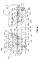
- Figure 4 shows a first preferred embodiment of the present invention, in which the liftable side rail of this invention is shown in relation to a bed.
- symbol 101 generally denotes a bed.
- the detailed structure of the bed is not illustrated and some components only are indicated by broken lines.
- Symbol 102 generally denotes a bed base intended to have a mattress (not illustrated) placed on it.
- the base 102 is divided into four base portions 102a, 102b, 102c, 102d respectively corresponding to the back, waist, thigh and legs of the user; they are connected to allow pivotal rotation respectively.
- the base 102 is supported above a base support frame 103.
- the deck portion 102b may be fixedly supported on the deck support frame 13 and the deck portions 102a and 102c may be pivotally rotatably connected to the deck portion 102b as described above, so as to be pivotally and liftably displaced by drive mechanisms (not illustrated).
- the support mechanism and drive mechanisms are not illustrated, since they are well known as described above.
- the base support frame 103 is supported by any known support mechanism on the floor 104 of a room etc.
- the support mechanism is not illustrated.
- the bed base support frame 103 may be supported at a predetermined height by stands with castors or may be supported by a lifting link mechanism above a base as shown in Figure 1.
- symbol 106 denotes a head board
- 107 denotes a foot board.
- Relative positions of parts of side rail assemblies generally indicated 100 will hereinafter be described in relation to their proximity (or otherwise) to the head end of the bead at which the head board 106 is located or the foot end of the bed at which the foot board 107 is located.
- a side rail member 112 is pivotally connected at opposite ends to respective support arms 108 at side rail member connection points 111.
- the support arms 108 are in turn pivotally connected at fixed installation points 109 to the bed base support frame 103.
- the support arms 108 are therefore mounted pivotally about a pivot axis extending transversely of the length of the bed 101.
- the side rail assembly 100 is movable between a raised service position and a lowered stowed position by turning the support arms 108 about the fixed installation points 109.
- the side rail assembly 100 may be secured in the service or stowed position by a locking mechanism as described below.
- Each support arm 108 has an outline of generally parallelogram shape and includes a parallelogram frame 110 which projects, laterally of a line L (shown in Figure 5) joining the fixed installation points 109 of the support arm 108 to the pivotal connection point of that arm 108 to the side rail member 112, in the region between the base 102 and the side rail member 112 when the side rail assembly 100 is in the service position.
- the line L lies approximately on the shorter diagonal of the frame 110, while the ends of the longer diagonal of the frame 110 generally indicated 113 define the extent to which the frame projects into the region between the base 102 and the side rail member 112 when in the service position.
- each side rail member 112 as each assembly 100 is moved from the service to the stowed position, is therefore towards respective adjacent ends of the bed 101.
- the side rail members 112 are closer to the ends of the bed in the stowed position than in the service position whereby a wide space can be obtained between them.
- the parallelogram frames 110 included in each support arm 108 extends both sides of the straight line (L), and so function as auxiliary side rail members.
- the dimension of the closed space b formed between the support arms 108 of each assembly 100 can be kept smaller by the frames 110, and the dimensional requirements of the side rail assembly 100 can be satisfied.
- the extent to which the frame 110 closest the head end extends towards the head end can be kept smaller since it does not have the function of narrowing the closed space b, unlike the other side of the same frame 110, which functions to narrow the closed space b in combination with the adjacent frame 110 on the other support arm 108 of the same assembly.
- the support arms 108 connected to each side rail member 112 are not necessarily required to be identical in form.
- the frames 110 are in line with side rail member 112 without protruding above or below the bed base. Therefore, the tops and bottoms of the frames 110 do not constitute any obstruction. Thus, even if the base of the bed is low in the height, the distance between the bottom of the side rail member 112 and the floor surface 104 can be large.
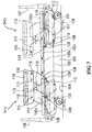
- Figure 5 is an expanded illustration of the side rail assembly 100 on the head end of Figure 4
- Figure 6 is a partial sectional view showing the holding mechanism. The components corresponding to those of Figures 4 and 5 are indicated by the same symbols.
- symbol 114 denotes a locking pin carried by the side rail member 112 and extending towards the support arm 108.
- the pin 114 is urged towards the support arm 108 by the resilience of a compression coil spring 115 or the like and can be retracted by pulling a control knob 116.
- a hole 117 into which the pin 114 can be introduced is formed in the support arm 108.
- a fitting hole 117 into which the pin 114 can be introduced is formed not only in the above position, but also in the position indicated by symbol 118 in Figure 5, of the support arm 108.
- the fitting holes 117 and 118 are located on the same circle around the connection point 111.
- the pins 114 are fitted in the fitting holes 117 of the support arms 108, and because of it, the support arms 108 cannot be pivotally rotated around the points 111 relative to the side rail members 112.
- the control knob 116 is first pulled, to retract the pin 114 from the hole 117.
- the support arms 108 as components of the quadrilateral link mechanism, can now be pivotally turned around the points 111 relative to the side rail member 112.
- the support arms 108 may be pivotally turned, for example, by manually manipulating a handling portion 119 provided at the top of the side rail member 112, to allow the side rail member 112 to turn about the points 111.
- the side rail member 112 is lowered towards the stowed position, in which movement of the points 111 follow an arcuate path and the member 112 descends in a horizontal orientation.
- the locking pins 114 are in register with fitting holes 118 formed in the support arms 108, and are pushed into the fitting holes 118 by the resilience of the compression coil spring 115 and, as described above, the support arms 108 cannot be pivotally rotated relative to the side rail member 112.
- the side rail member 112 is held in the lowered position, which is the stowed position of the side rail assembly 100.
- the side rail member 112 can be moved from the stowed position to the service position by reversing the above action.
- Figure 7 shows a second embodiment, in which the liftable side rail of the invention is applied to a bed.
- This second preferred embodiment differs from the first preferred embodiment only in respect of the support arms 108, and remains identical in all other basic components and mode of action.
- the same components as those of the first preferred embodiment are indicated by the same symbols.
- the support arms 108 include parallelogram frames 110.
- each of the support arms 108 includes a solid plate 110 with a generally parallelogram outline to give the arms a generally P-shape form.
- the shorter diagonal of the plate 110 joins the connection point 111 of the side rail member 112 and the installation point 109, while the ends of the longer diagonal of the plate 110 generally indicated 113 define the extent to which the plate 110 projects into the region between the base 103 and the side rail member 112 in the service position. Support arms 108 of this construction can be manufactured easily.
- Figure 8 shows a third embodiment, in which the liftable side rail of the invention is applied to a bed.
- This third embodiment is different from the first and second embodiments only in the construction of support arms 108, and remains identical in the other basic components, and mode of action.
- the same components as those of the first embodiment are indicated by the same symbols.
- each of the support arms 108 comprises frame portions 120 extending either side of a rectilinear arm 121 which directly connects the installation point 109 and the side rail member connection point 111.
- the parts of the support arm 108 which are load-bearing and those which function as auxiliary side rail members may be changed by using differently shaped and configured support arms.
- a liftable side rail formed as an embodiment of the present invention has the advantage that in the case of a side rail member which is moved to ascend and descend by the pivotal rotation of support arms, the conflicting requirements of keeping the bed base height low and keeping the distance between the bottom of the side rail member and the floor surface in the stowed position large can be solved. Even a bed with a low base height can have a side rail member with a required height and yet allow the distance between the bottom of the side rail member and the floor surface to be kept large. In addition, since it is required only to change the support arms, a liftable side rail with the required functions can be obtained very simply and at a low cost.
Abstract
Description
- The present invention relates generally to side rails disposed to one side of a bed or the like for preventing the bedding such as a bed quilt or a user such as a patient from falling, and particularly a side rail assembly incorporating a lifting mechanism for liftable side rails, in which the side rail can be lifted and lowered between a raised service position in which it projects above the plane of the bed and a stowed position below the plane of the bed.
- As used in this specification the term "bed or the like" will be understood to include hospital trolleys, operating tables, stretchers and any other structure incorporating a horizontal surface on which a user may lie. Conventional side rails for a bed or the like include a detachable side rail assembly in the form of a side rail frame and support columns which are inserted into sockets formed in the bed base for supporting the side rail in its service condition, and a liftable side rail in which a side rail frame is supported liftably by a lifting mechanism to be used in a raised position and stowed in a lowered position to avoid disturbance by the top of the side rail frame. Known side rails also include a full side rail which extends along an entire side of a bed and a partial side rail which extends only part way along the side of a bed and requires other side rails to cover the whole of the side of a bed. Medical beds are specified with reference to the dimensions of respective portions by standards to allow their safe use.
For example, for partial side rails, IEC specifies the dimensions of respective portions as described in more detail below. - The object of the present invention is to provide a liftable side rail, the side rail frame of which can be lifted and lowered by the pivotal turning of support arms and to allow the standard values of the dimensions of the side rail frame to be satisfied, while allowing the bed base height to be low and allowing the distance between the bottom of the side rail frame and the floor surface to be kept large in the stowed position.
- According to the present invention, therefore, there is provided a liftable side rail assembly for a bed or the like, comprising a side rail member pivotally connected at or adjacent opposite ends thereof by respective support arms which are in turn pivotally connected at fixed installation points to a bed base or other fixed support whereby to allow the side rail assembly to be moved between a raised service position and a lowered, stowed position by turning the arms about their pivotal connection to the bed base or other fixed support, characterised in that each of the said support arms is shaped or carries a member so shaped as to project, laterally of a line joining the said fixed installation point of a support arm to the pivotal connection of that arm to the side rail member, into the region between the bed base or other fixed support and the support rail member when the side rail assembly is in the said service position.
- In a preferred embodiment each support arm has an outline of generally parallelogram shape and a line joining the pivotal connection of the support arm to the side rail member and the fixed installation point lies approximately on the shorter diagonal thereof.
- In some embodiments at least one of the said support arms is substantially solid. However, in other embodiments at least one of the support arms may be formed as an open frame.
- In some embodiments there are two side rail assemblies. In such embodiments the side rail assemblies may be so orientated that the horizontal component of movement of each side rail member, as each side rail assembly is moved from the service to the stowed position, is towards a respective adjacent end of the bed, whereby the side rail members are closer to the ends of the bed in the stowed position than in the service position.
- A liftable side rail assembly formed as an embodiment of the invention may be characterised in that the outline shape of at least one of the said support arms has a cutaway portion in the vicinity of that end of the longer diagonal which is lowermost in the service position.
Such a cutaway portion may define a recess which a suitably shaped portion of an adjacent support arm may protrude into in the service or stowed position. It may also allow two support arms to pivot past each other during the stowing or erecting movement. This may, for example, allow two support arms to lie closer together than might otherwise be possible. - The present invention also comprehends a bed equipped with a side rail assembly as hereinbefore described. The bed may have two side rail assemblies along at least one side thereof.
- Preferably, when the side rail assembly is held in the lower stowed position, the support arm and/or member carried thereby lie alongside the side rail frame without protruding above or below the bed base so as not to constitute any obstruction. Therefore, even if the bed base is low in the height, the distance between the bottom of the side rail frame and the floor surface can be kept large.
- Various embodiments of the present invention will now be more particularly described, by way of example, with reference to the accompanying drawings in which:
- Figure 1 is a side view of a bed, showing prior art partial side rails;
- Figure 2 is a side view of a bed, to showing prior art partial side rails.
- Figure 3 shows a prior art modification to the side rails shown in Figure 1, in which the vertical height of the side rail frames is kept smaller to keep the distance between the bottom of the side rail frames and the floor surface larger.
- Figure 4 is a side view showing a preferred embodiment, in which the liftable side rail of this invention is applied to a bed;
- Figure 5 is an expanded illustration for illustrating the action of an important portion of Figure 1;
- Figure 6 is a sectional view showing a preferred embodiment of a locking mechanism for holding the side rail frame at the service position and the stowed position;
- Figure 7 is a side view showing another preferred embodiment, in which the liftable side rail of this invention is applied to a bed;
- Figure 8 is a side view showing a further preferred embodiment, in which the liftable side rail of this invention is applied to a bed;
-
- Preferred embodiments of this invention are described below in more detail with reference to Figures 4 to 8. First, however, the prior art structures and the problems which the present invention addresses will be more particularly described with reference to Figures 1 to 3.
- The components of Figure 1 will be explained first.
Symbol 1 denotes the base of a bed which is liftably supported above asupport frame 2 by anysuitable link mechanism 3. Thebase 1 can be driven to be raised and lowered by a drive mechanism (not shown). - Partial side rails 4 are supported by any suitable support mechanism at one side of the
base 1 and are shown in a service position. Two such partial side rails 4 are installed side-by-side , to cover the entire lateral side of thebase 1. Each of the partial side rails 4 comprises a side rail frame 5 and legs 6 which are inserted into fitting holes (not shown) formed in thebase 1. As for other illustrated components,symbol 7 denotes a mattress placed on thebase 1; 8, a head board; and 9, a foot board. - The specified dimensions of the respective portions shown in Figure 1 are described below.
- The dimension indicated by A is the dimension of each closed space formed in the side rail frame 5 of the side rail 4. The dimension of each space A is specified to be 120 mm or less, to prevent the head of the user entering into the space.
- The dimension indicated by D is the dimension of the gap between two adjacent side rail frames 5 and the
head board 8 or thefoot board 9. The dimension of any of these gaps is specified to be 60 mm or less to prevent the neck of the user entering into the gap, or to be 235 mm or more, to prevent the head from being caught in the gap. - The dimension indicated by F is the dimension of the gap between the bottom of the side rail frames 5 and the
base 1. The dimension of this gap is specified to be 120 mm or less to prevent the head entering into it when there is no risk of the neck entering into it, or to be 60 mm or less to prevent the neck from entering into the gap below the side rail frame 5 when the neck can enter into it. - G1 and G2 indicate the horizontal lengths of the side rail frames 5 of the respective side rail assemblies 4, and are specified to satisfy a formula of G1 + G2 >L/2, where L is the total length L of the
bed base 1. - The dimension indicated by H is the height of the side rail frame 5, that is the dimension between the upper surface of a mattress and the top of the side rail frame 5, and is specified to be 220 mm or more.
- The dimensions of respective portions of the partial side rail assemblies described above are also applicable when liftable side rails are used in a raised position.
- A prior art example of liftable side rails, particularly a partial side rail is described below with reference to Figure 2.
- In Figure 2, a bed equipped with liftable side rails is generally indicated 11. In this drawing, the detailed structure of the bed is not illustrated, some components being indicated by broken lines.
- Symbol 12 denotes a base intended to have a mattress (not illustrated) placed on it. The base 12 is divided into four
portions base support frame 13. In use thedeck portion 12b may be fixedly supported on thebase support frame 13. Thebed base portions bed base portion 12b, and pivotally and liftably supported by suitable drive mechanisms (not shown). The support mechanism and drive mechanisms are not illustrated, since they are well-known. - The bed
base support frame 13 is supported by any appropriate support mechanism (not shown) on thefloor 15. For example the bedbase support frame 13 may be supported at a predetermined height by stands with castors or may be liftably supported by a lifting link mechanism above a base as shown in Figure 1. In Figure 2, symbol 17 denotes a head board, and 18, a foot board. - Towards the head board 17 and the
foot board 18 of thebase support frame 13, pairs ofsupport arms support arm side rails frames support arms bed base portions base support frame 13. - In the above example the
side rail frames support arms side rail frame 20a on the head board 17 end in its service position in solid lines, and theside rail frame 20b on thefoot board 18 end in its stowed position in solid lines. The locking mechanism for securing theside rail frames - The side rails
frames - As described above the side rail frames 20a and 20b, which are supported by a lifting mechanism in the service position and also in the stowed position, must conform to the standard dimensions as described above in the service position. However, in the stowed position there are desirable dimensions in view of convenience.
- In the use of the bed shown in Figure 2, when the side rail frames 20a and 20b are in the stowed position, an attendant may nurse the user such as a patient lying on the bed, or the table of a movable bed side table may be moved and located above the bed. In the former case, the attendant may need to insert his/her legs into the gap between the bottom of the side rail frames 20a and 20b in the stowed position and the
floor surface 15 of the sickroom etc, and in the latter case, the base of the bed side table is moved inside the gap d. It is thus desirable that the gap d is large. - However, recently there is a tendency to keep the height of the bed base 12 low, because of various advantages, for example a patient can easily get on and off the bed base 12 and sit at the edge of the base 12 and the attendant can more easily nurse if the bed is low in base height.
- In the case of liftable side rails, the existing side rail frames 20a and 20b which can be lifted and lowered in parallel by the pivotal rotation of
support arms floor surface 15 large. - Figure 3 shows an attempt to keep the distance d between the bottom of the side rail frames 20a and 20b and the
floor surface 15 large in the bed of Figure 2. - In the bed of Figure 3, the vertical height c of the side rail frames 20a and 20b is less than that of the side rail frames 20a and 20b of Figure 2, to keep the distance d between the bottom of the side rail frames 20a and 20b and the
floor surface 15 large, while keeping the distance e between thefloor surface 15 and the base 12 and the distance a between the base 12 and the tops of the side rail frames 20a and 20b, that is the height of the side rail frames 20a and 20b above the base 12, equal to those of the bed of Figure 2. - If the vertical height c of the side rail frames 20a and 20b is kept small in this way, the distance d between the bottom of the side rail frames 20a and 20b and the
floor surface 15 is increased. However, as a consequence the dimension indicated by b in the drawing becomes large, and there is a possibility that the dimension indicated by A in the above-mentioned standard may not be satisfied. - Hitherto, therefore, these dimensions have been set considering the above-mentioned conflicting requirements, and it is very difficult to keep the distance d between the bottom of the side rail frames 20a and 20b and the
floor surface 15 large while satisfying the respective standard values of the side rails. - Figure 4 shows a first preferred embodiment of the present invention, in which the liftable side rail of this invention is shown in relation to a bed. In the drawing,
symbol 101 generally denotes a bed. In this drawing, the detailed structure of the bed is not illustrated and some components only are indicated by broken lines. - Symbol 102 generally denotes a bed base intended to have a mattress (not illustrated) placed on it. The base 102 is divided into four
base portions base support frame 103. Thedeck portion 102b may be fixedly supported on thedeck support frame 13 and thedeck portions deck portion 102b as described above, so as to be pivotally and liftably displaced by drive mechanisms (not illustrated). The support mechanism and drive mechanisms are not illustrated, since they are well known as described above. - The
base support frame 103 is supported by any known support mechanism on thefloor 104 of a room etc. The support mechanism is not illustrated. For example, the bedbase support frame 103 may be supported at a predetermined height by stands with castors or may be supported by a lifting link mechanism above a base as shown in Figure 1. In Figure 4,symbol 106 denotes a head board, and 107 denotes a foot board. - Relative positions of parts of side rail assemblies generally indicated 100 will hereinafter be described in relation to their proximity (or otherwise) to the head end of the bead at which the
head board 106 is located or the foot end of the bed at which thefoot board 107 is located. - A
side rail member 112 is pivotally connected at opposite ends torespective support arms 108 at side rail member connection points 111. Thesupport arms 108 are in turn pivotally connected atfixed installation points 109 to the bedbase support frame 103. Thesupport arms 108 are therefore mounted pivotally about a pivot axis extending transversely of the length of thebed 101. In the following description, like components are indicated by the same symbols for the sake of convenience. - The
side rail assembly 100 is movable between a raised service position and a lowered stowed position by turning thesupport arms 108 about the fixed installation points 109. Theside rail assembly 100 may be secured in the service or stowed position by a locking mechanism as described below. - Each
support arm 108 has an outline of generally parallelogram shape and includes aparallelogram frame 110 which projects, laterally of a line L (shown in Figure 5) joining the fixed installation points 109 of thesupport arm 108 to the pivotal connection point of thatarm 108 to theside rail member 112, in the region between the base 102 and theside rail member 112 when theside rail assembly 100 is in the service position. The line L lies approximately on the shorter diagonal of theframe 110, while the ends of the longer diagonal of theframe 110 generally indicated 113 define the extent to which the frame projects into the region between the base 102 and theside rail member 112 when in the service position. - In this embodiment the
support arms 108 at the head end are designed to be pivotally rotated clockwise for ascending and to be pivotally rotated anticlockwise for descending; conversely thesupport arms 108 at the foot end are designed to be pivotally rotated clockwise for descending and to be pivotally rotated anticlockwise for ascending. The horizontal component of movement of eachside rail member 112, as eachassembly 100 is moved from the service to the stowed position, is therefore towards respective adjacent ends of thebed 101. Theside rail members 112 are closer to the ends of the bed in the stowed position than in the service position whereby a wide space can be obtained between them. - In Figure 4, at the head end, the components of the
side rail assembly 100 in the service position are drawn by solid lines, and the components of theside rail assembly 100 in the stowed position are drawn by broken lines. Conversely at the foot end the components of theside rail assembly 100 in the service position are drawn by broken lines, and the components of theside rail assembly 100 in the stored position are drawn by solid lines. - As shown in Figures 1 and 2, in this preferred embodiment the parallelogram frames 110 included in each
support arm 108 extends both sides of the straight line (L), and so function as auxiliary side rail members. Particularly the dimension of the closed space b formed between thesupport arms 108 of eachassembly 100 can be kept smaller by theframes 110, and the dimensional requirements of theside rail assembly 100 can be satisfied. - The extent to which the
frame 110 closest the head end extends towards the head end can be kept smaller since it does not have the function of narrowing the closed space b, unlike the other side of thesame frame 110, which functions to narrow the closed space b in combination with theadjacent frame 110 on theother support arm 108 of the same assembly. - The
support arms 108 connected to eachside rail member 112 are not necessarily required to be identical in form. - As can be seen from the drawing, when the
side rail assembly 100 is held in the lower, stowed position, theframes 110 are in line withside rail member 112 without protruding above or below the bed base. Therefore, the tops and bottoms of theframes 110 do not constitute any obstruction. Thus, even if the base of the bed is low in the height, the distance between the bottom of theside rail member 112 and thefloor surface 104 can be large. - A preferred embodiment of a mechanism for holding a side rail assembly in the stowed and service positions is described below with reference to Figures 4 to 6. Figure 5 is an expanded illustration of the
side rail assembly 100 on the head end of Figure 4, and Figure 6 is a partial sectional view showing the holding mechanism. The components corresponding to those of Figures 4 and 5 are indicated by the same symbols. - In Figure 6,
symbol 114 denotes a locking pin carried by theside rail member 112 and extending towards thesupport arm 108. Thepin 114 is urged towards thesupport arm 108 by the resilience of acompression coil spring 115 or the like and can be retracted by pulling acontrol knob 116. Ahole 117 into which thepin 114 can be introduced is formed in thesupport arm 108. - With reference to Figure 5, a
fitting hole 117 into which thepin 114 can be introduced is formed not only in the above position, but also in the position indicated bysymbol 118 in Figure 5, of thesupport arm 108. The fitting holes 117 and 118 are located on the same circle around theconnection point 111. - As shown by the solid lines of Figure 5, the
pins 114 are fitted in thefitting holes 117 of thesupport arms 108, and because of it, thesupport arms 108 cannot be pivotally rotated around thepoints 111 relative to theside rail members 112. - For this reason, the
side rail frame 112 and the pair ofsupport arms 108 which are components of a quaderateral link mechanism are held in the position shown in a solid line in Figure 5 - this is the service position of theside rail assembly 100. - To move the
side rail assembly 100 from the service position to the stowed position thecontrol knob 116 is first pulled, to retract thepin 114 from thehole 117. As a result, thesupport arms 108, as components of the quadrilateral link mechanism, can now be pivotally turned around thepoints 111 relative to theside rail member 112. Thesupport arms 108 may be pivotally turned, for example, by manually manipulating ahandling portion 119 provided at the top of theside rail member 112, to allow theside rail member 112 to turn about thepoints 111. Theside rail member 112 is lowered towards the stowed position, in which movement of thepoints 111 follow an arcuate path and themember 112 descends in a horizontal orientation. - When the
side rail member 112 reaches the lower predetermined position, the locking pins 114 are in register withfitting holes 118 formed in thesupport arms 108, and are pushed into thefitting holes 118 by the resilience of thecompression coil spring 115 and, as described above, thesupport arms 108 cannot be pivotally rotated relative to theside rail member 112. Theside rail member 112 is held in the lowered position, which is the stowed position of theside rail assembly 100. - The
side rail member 112 can be moved from the stowed position to the service position by reversing the above action. - Figure 7 shows a second embodiment, in which the liftable side rail of the invention is applied to a bed. This second preferred embodiment differs from the first preferred embodiment only in respect of the
support arms 108, and remains identical in all other basic components and mode of action. The same components as those of the first preferred embodiment are indicated by the same symbols. - In the first embodiment, the
support arms 108 include parallelogram frames 110. However, in the second preferred embodiment, each of thesupport arms 108 includes asolid plate 110 with a generally parallelogram outline to give the arms a generally P-shape form. The shorter diagonal of theplate 110 joins theconnection point 111 of theside rail member 112 and theinstallation point 109, while the ends of the longer diagonal of theplate 110 generally indicated 113 define the extent to which theplate 110 projects into the region between the base 103 and theside rail member 112 in the service position.Support arms 108 of this construction can be manufactured easily. - Figure 8 shows a third embodiment, in which the liftable side rail of the invention is applied to a bed. This third embodiment is different from the first and second embodiments only in the construction of
support arms 108, and remains identical in the other basic components, and mode of action. The same components as those of the first embodiment are indicated by the same symbols. - In the third embodiment, each of the
support arms 108 comprisesframe portions 120 extending either side of arectilinear arm 121 which directly connects theinstallation point 109 and the side railmember connection point 111. - The parts of the
support arm 108 which are load-bearing and those which function as auxiliary side rail members may be changed by using differently shaped and configured support arms. - A liftable side rail formed as an embodiment of the present invention has the advantage that in the case of a side rail member which is moved to ascend and descend by the pivotal rotation of support arms, the conflicting requirements of keeping the bed base height low and keeping the distance between the bottom of the side rail member and the floor surface in the stowed position large can be solved. Even a bed with a low base height can have a side rail member with a required height and yet allow the distance between the bottom of the side rail member and the floor surface to be kept large. In addition, since it is required only to change the support arms, a liftable side rail with the required functions can be obtained very simply and at a low cost.
Claims (8)
- A liftable side rail assembly 100 for a bed 101 or the like, comprising a side rail member 112 pivotally connected at or adjacent opposite ends thereof by respective support arms 108 which are in turn pivotally connected at fixed installation points 109 to a bed base 103 or other fixed support whereby to allow the side rail assembly 100 to be moved between a raised service position and a lowered, stowed position by turning the arms 108 about their pivotal connection 109 to the bed base 103 or other fixed support, characterised in that each of the said support arms 108 is shaped or carries a member so shaped as to project, laterally of a line joining the said fixed installation point 109 of a support arm 109 to the pivotal connection 111 of that arm 108 to the side rail member 112, into the region between the bed base 103 or other fixed support and the support rail member 112 when the side rail assembly 100 is in the said service position.
- A liftable side rail assembly 100 according to Claim 1 characterised in that each support arm 108 has an outline of generally parallelogram shape, and in that a line joining the pivotal connection 111 of the support arm 108 to the side rail member 112 and the fixed installation point 109 lies approximately on the shorter diagonal thereof.
- A liftable side rail assembly 100 according to Claim 1 or Claim 2, characterised in that at least one of the said support arms 108 is substantially solid.
- A liftable side rail assembly 100 according to Claim 1 or Claim 2, characterised in that at least one of the said support arms 108 is formed as an open frame.
- A liftable side rail assembly according to any of Claims 1 to 4, characterised in that there are two side rail assemblies 100 being so orientated that the horizontal component of movement of each side rail member 112, as each side rail assembly 100 is moved from the service to the stowed position, is towards a respective adjacent end of the bed 101, whereby the side rail members 112 are closer to the ends of the bed in the stowed position than in the service position.
- A liftable side rail assembly 100 according to any of Claims 2 to 5, characterised in that the outline shape of at least one of the said support arms 108 has a cutaway portion in the vicinity of that end of the longer diagonal which is lowermost in the service position.
- A bed 101, characterised in that it is equipped with a side rail assembly 100 according to any of Claims 1 to 6.
- A bed 101 according to Claim 7, characterised in that it has two side rail assemblies 100 along at least one side thereof.
Applications Claiming Priority (3)
| Application Number | Priority Date | Filing Date | Title |
|---|---|---|---|
| JP35318199A JP3549093B2 (en) | 1999-12-13 | 1999-12-13 | Retractable side fence in bed etc. |
| JP35318199 | 1999-12-13 | ||
| US10/005,126 US6564404B1 (en) | 1999-12-13 | 2001-12-07 | Liftable side rail for a lying table such as a bed |
Publications (3)
| Publication Number | Publication Date |
|---|---|
| EP1108410A2 true EP1108410A2 (en) | 2001-06-20 |
| EP1108410A3 EP1108410A3 (en) | 2001-07-11 |
| EP1108410B1 EP1108410B1 (en) | 2006-08-09 |
Family
ID=27624581
Family Applications (1)
| Application Number | Title | Priority Date | Filing Date |
|---|---|---|---|
| EP00303237A Expired - Lifetime EP1108410B1 (en) | 1999-12-13 | 2000-04-17 | A liftable side rail assembly for a bed or the like |
Country Status (3)
| Country | Link |
|---|---|
| US (1) | US6564404B1 (en) |
| EP (1) | EP1108410B1 (en) |
| JP (1) | JP3549093B2 (en) |
Cited By (5)
| Publication number | Priority date | Publication date | Assignee | Title |
|---|---|---|---|---|
| WO2003070061A1 (en) * | 2002-02-19 | 2003-08-28 | Hill-Rom Services, Inc. | Bed siderail apparatus |
| FR2854780A1 (en) * | 2003-05-12 | 2004-11-19 | Hill Rom Sas | Adjustable hospital bed comprises frame carrying mattress and is fitted along side with barrier able to be erected vertically, with top higher than mattress upper surface, or retracted below mattress upper surface |
| US7712167B2 (en) | 2007-07-06 | 2010-05-11 | Hill-Rom S.A.S. | Patient bed with a retractable side barrier |
| US7712165B2 (en) | 2007-07-13 | 2010-05-11 | Hill-Rom S.A.S. | Bed with a retractable side barrier |
| US7793369B2 (en) | 2007-09-28 | 2010-09-14 | Hill-Rom Sas | Bed having a retractable side barrier movable to multiple predetermined positions |
Families Citing this family (15)
| Publication number | Priority date | Publication date | Assignee | Title |
|---|---|---|---|---|
| JP3384555B2 (en) * | 1999-05-21 | 2003-03-10 | パラマウントベッド株式会社 | Elevating mechanism for elevating side fences on a supine table such as a bed |
| US7073219B2 (en) | 2004-01-06 | 2006-07-11 | Teknion Concept | Side rail, hospital bed including the same, method of operating associated thereto and kit for assembling the side rail |
| DE602005023143D1 (en) | 2004-04-30 | 2010-10-07 | Hill Rom Services Inc | PATIENT SUPPORT |
| CA2523168C (en) * | 2004-10-18 | 2014-02-18 | Stryker Corporation | Bed siderail |
| US7712166B2 (en) * | 2004-12-03 | 2010-05-11 | Stryker Corporation | Bed siderail and support structure |
| US7559101B2 (en) | 2005-02-16 | 2009-07-14 | Kci Licensing, Inc. | Side rail pad/panel system for patient support apparatus |
| AU2005203585B2 (en) * | 2005-08-11 | 2011-10-27 | Hill-Rom Pty Ltd | A rail for hospital bed |
| US7784125B2 (en) * | 2005-08-16 | 2010-08-31 | Stryker Canadian Management, Inc. | Movable siderail apparatus for use with a patient support apparatus |
| US8104118B2 (en) * | 2008-01-21 | 2012-01-31 | Stryker Corporation | Hospital bed |
| US8239986B2 (en) | 2008-03-13 | 2012-08-14 | Hill-Rom Services, Inc. | Siderail assembly for a patient-support apparatus |
| JP2011524206A (en) | 2008-06-13 | 2011-09-01 | ヒル−ロム サービシーズ,インコーポレイティド | Bedside article support apparatus and system |
| US20110010854A1 (en) | 2009-07-15 | 2011-01-20 | Zerhusen Robert M | Siderail with storage area |
| US11090209B2 (en) | 2017-06-20 | 2021-08-17 | Stryker Corporation | Patient support apparatus with control system and method to avoid obstacles during reconfiguration |
| KR102156496B1 (en) * | 2019-04-02 | 2020-09-15 | (주)한국베드메디칼 | A railing for patient bed |
| KR102361754B1 (en) * | 2020-02-12 | 2022-02-11 | 주식회사 나인벨 | Electric medical bed |
Family Cites Families (10)
| Publication number | Priority date | Publication date | Assignee | Title |
|---|---|---|---|---|
| US1059515A (en) * | 1912-03-18 | 1913-04-22 | Mary Barr | Auxiliary side rail for bedsteads and similar appliances. |
| US2676341A (en) * | 1953-05-19 | 1954-04-27 | Joseph P Leone | Folding side guard for hospital and other beds |
| US2799869A (en) * | 1955-09-28 | 1957-07-23 | Joseph P Leone | Folding side guard for beds |
| US2976548A (en) * | 1957-11-25 | 1961-03-28 | Gustave R Maertins | Means for mounting a folding side guard on a bed frame |
| US3063066A (en) * | 1958-12-17 | 1962-11-13 | Hildegarde V Peck | Sidegate for beds |
| DE8529108U1 (en) * | 1985-10-12 | 1986-01-16 | L. & C. Arnold Gmbh, 7060 Schorndorf | Link frame bed |
| JPH0716463B2 (en) * | 1992-01-27 | 1995-03-01 | パラマウントベッド株式会社 | Side fence device for bed raising |
| US6351861B1 (en) * | 1998-05-29 | 2002-03-05 | Hill-Rom Services, Inc. | Bed frame |
| DE29705820U1 (en) * | 1997-04-02 | 1997-05-28 | Koetter Helmut | Side rest for a hospital and or nursing bed, swiveling |
| EP1152674B1 (en) * | 1999-01-22 | 2006-11-02 | Hill-Rom Services, Inc. | Convertible stretcher |
-
1999
- 1999-12-13 JP JP35318199A patent/JP3549093B2/en not_active Expired - Fee Related
-
2000
- 2000-04-17 EP EP00303237A patent/EP1108410B1/en not_active Expired - Lifetime
-
2001
- 2001-12-07 US US10/005,126 patent/US6564404B1/en not_active Expired - Lifetime
Non-Patent Citations (1)
| Title |
|---|
| None |
Cited By (9)
| Publication number | Priority date | Publication date | Assignee | Title |
|---|---|---|---|---|
| US6779209B2 (en) | 2000-12-29 | 2004-08-24 | Hill-Rom Services, Inc. | Bed siderail apparatus |
| WO2003070061A1 (en) * | 2002-02-19 | 2003-08-28 | Hill-Rom Services, Inc. | Bed siderail apparatus |
| FR2854780A1 (en) * | 2003-05-12 | 2004-11-19 | Hill Rom Sas | Adjustable hospital bed comprises frame carrying mattress and is fitted along side with barrier able to be erected vertically, with top higher than mattress upper surface, or retracted below mattress upper surface |
| WO2004100724A2 (en) * | 2003-05-12 | 2004-11-25 | Hill-Rom S.A.S. | Bed with means for adjusting the position of a barrier element in relation to the mattress |
| WO2004100724A3 (en) * | 2003-05-12 | 2005-02-03 | Hill Rom Sas | Bed with means for adjusting the position of a barrier element in relation to the mattress |
| US7712167B2 (en) | 2007-07-06 | 2010-05-11 | Hill-Rom S.A.S. | Patient bed with a retractable side barrier |
| US7814588B2 (en) | 2007-07-06 | 2010-10-19 | Hill-Rom S.A.S. | Patient bed with a retractable side barrier |
| US7712165B2 (en) | 2007-07-13 | 2010-05-11 | Hill-Rom S.A.S. | Bed with a retractable side barrier |
| US7793369B2 (en) | 2007-09-28 | 2010-09-14 | Hill-Rom Sas | Bed having a retractable side barrier movable to multiple predetermined positions |
Also Published As
| Publication number | Publication date |
|---|---|
| JP3549093B2 (en) | 2004-08-04 |
| US6564404B1 (en) | 2003-05-20 |
| JP2001161500A (en) | 2001-06-19 |
| EP1108410B1 (en) | 2006-08-09 |
| EP1108410A3 (en) | 2001-07-11 |
Similar Documents
| Publication | Publication Date | Title |
|---|---|---|
| EP1108410B1 (en) | A liftable side rail assembly for a bed or the like | |
| US6691345B2 (en) | Lifting mechanism for liftable side rails for a lying table such as a bed | |
| US5636394A (en) | Hospital bed with rack and pinion stabilizer | |
| US8887329B2 (en) | Methods of translating hospital chair beds with articulating foot sections | |
| EP0850038B1 (en) | Bed having a reduced-shear pivot and step deck combination | |
| US7082882B2 (en) | Frame mounted overbed table | |
| US8387184B2 (en) | Auto contour handle apparatus | |
| US6694549B2 (en) | Bed frame with reduced-shear pivot | |
| US6795988B2 (en) | Bed, particularly a hospital or nursing bed | |
| US20120124746A1 (en) | Patient support apparatus with egress units | |
| US20050144720A1 (en) | Side rail, hospital bed including the same, method of operating associated thereto and kit for assembling the side rail | |
| US20130086746A1 (en) | Patient support apparatus with movable siderail assembly | |
| CA2300473A1 (en) | Siderail extender | |
| US11116322B2 (en) | Split adjustable mattress foundation for multiple users | |
| EP1053735B1 (en) | A side rail assembly for a bed or the like | |
| US6662392B2 (en) | Epidural patient support | |
| CN104739083B (en) | Structure of side part of bed | |
| JPH0527887Y2 (en) | ||
| JP2546966B2 (en) | Medical bed | |
| GB2284147A (en) | Pivoting safety rail for beds | |
| US4461047A (en) | Ledge bed overlay | |
| CA2454931C (en) | Side rail, hospital bed including the same, method of operating associated thereto and kit for assembling the side rail | |
| JP3444493B2 (en) | Locking mechanism for casters in beds etc. | |
| JPH0838555A (en) | Bed for concentrated treatment room | |
| EP1552772A1 (en) | Side Rail, hospital bed including the same, method of operating associated thereto and kit for assembling the side rail |
Legal Events
| Date | Code | Title | Description |
|---|---|---|---|
| PUAI | Public reference made under article 153(3) epc to a published international application that has entered the european phase |
Free format text: ORIGINAL CODE: 0009012 |
|
| PUAL | Search report despatched |
Free format text: ORIGINAL CODE: 0009013 |
|
| AK | Designated contracting states |
Kind code of ref document: A2 Designated state(s): AT BE CH CY DE DK ES FI FR GB GR IE IT LI LU MC NL PT SE |
|
| AX | Request for extension of the european patent |
Free format text: AL;LT;LV;MK;RO;SI |
|
| AK | Designated contracting states |
Kind code of ref document: A3 Designated state(s): AT BE CH CY DE DK ES FI FR GB GR IE IT LI LU MC NL PT SE |
|
| AX | Request for extension of the european patent |
Free format text: AL;LT;LV;MK;RO;SI |
|
| 17P | Request for examination filed |
Effective date: 20011009 |
|
| AKX | Designation fees paid |
Free format text: AT BE CH CY DE DK ES FI FR GB GR IE IT LI LU MC NL PT SE |
|
| 17Q | First examination report despatched |
Effective date: 20030314 |
|
| GRAP | Despatch of communication of intention to grant a patent |
Free format text: ORIGINAL CODE: EPIDOSNIGR1 |
|
| GRAS | Grant fee paid |
Free format text: ORIGINAL CODE: EPIDOSNIGR3 |
|
| GRAA | (expected) grant |
Free format text: ORIGINAL CODE: 0009210 |
|
| AK | Designated contracting states |
Kind code of ref document: B1 Designated state(s): AT BE CH CY DE DK ES FI FR GB GR IE IT LI LU MC NL PT SE |
|
| PG25 | Lapsed in a contracting state [announced via postgrant information from national office to epo] |
Ref country code: IT Free format text: LAPSE BECAUSE OF FAILURE TO SUBMIT A TRANSLATION OF THE DESCRIPTION OR TO PAY THE FEE WITHIN THE PRESCRIBED TIME-LIMIT;WARNING: LAPSES OF ITALIAN PATENTS WITH EFFECTIVE DATE BEFORE 2007 MAY HAVE OCCURRED AT ANY TIME BEFORE 2007. THE CORRECT EFFECTIVE DATE MAY BE DIFFERENT FROM THE ONE RECORDED. Effective date: 20060809 Ref country code: LI Free format text: LAPSE BECAUSE OF FAILURE TO SUBMIT A TRANSLATION OF THE DESCRIPTION OR TO PAY THE FEE WITHIN THE PRESCRIBED TIME-LIMIT Effective date: 20060809 Ref country code: NL Free format text: LAPSE BECAUSE OF FAILURE TO SUBMIT A TRANSLATION OF THE DESCRIPTION OR TO PAY THE FEE WITHIN THE PRESCRIBED TIME-LIMIT Effective date: 20060809 Ref country code: AT Free format text: LAPSE BECAUSE OF FAILURE TO SUBMIT A TRANSLATION OF THE DESCRIPTION OR TO PAY THE FEE WITHIN THE PRESCRIBED TIME-LIMIT Effective date: 20060809 Ref country code: BE Free format text: LAPSE BECAUSE OF FAILURE TO SUBMIT A TRANSLATION OF THE DESCRIPTION OR TO PAY THE FEE WITHIN THE PRESCRIBED TIME-LIMIT Effective date: 20060809 Ref country code: CH Free format text: LAPSE BECAUSE OF FAILURE TO SUBMIT A TRANSLATION OF THE DESCRIPTION OR TO PAY THE FEE WITHIN THE PRESCRIBED TIME-LIMIT Effective date: 20060809 Ref country code: FI Free format text: LAPSE BECAUSE OF FAILURE TO SUBMIT A TRANSLATION OF THE DESCRIPTION OR TO PAY THE FEE WITHIN THE PRESCRIBED TIME-LIMIT Effective date: 20060809 |
|
| REG | Reference to a national code |
Ref country code: GB Ref legal event code: FG4D |
|
| REG | Reference to a national code |
Ref country code: CH Ref legal event code: EP |
|
| REG | Reference to a national code |
Ref country code: IE Ref legal event code: FG4D |
|
| REF | Corresponds to: |
Ref document number: 60029912 Country of ref document: DE Date of ref document: 20060921 Kind code of ref document: P |
|
| PG25 | Lapsed in a contracting state [announced via postgrant information from national office to epo] |
Ref country code: DK Free format text: LAPSE BECAUSE OF FAILURE TO SUBMIT A TRANSLATION OF THE DESCRIPTION OR TO PAY THE FEE WITHIN THE PRESCRIBED TIME-LIMIT Effective date: 20061109 Ref country code: SE Free format text: LAPSE BECAUSE OF FAILURE TO SUBMIT A TRANSLATION OF THE DESCRIPTION OR TO PAY THE FEE WITHIN THE PRESCRIBED TIME-LIMIT Effective date: 20061109 |
|
| PG25 | Lapsed in a contracting state [announced via postgrant information from national office to epo] |
Ref country code: ES Free format text: LAPSE BECAUSE OF FAILURE TO SUBMIT A TRANSLATION OF THE DESCRIPTION OR TO PAY THE FEE WITHIN THE PRESCRIBED TIME-LIMIT Effective date: 20061120 |
|
| PG25 | Lapsed in a contracting state [announced via postgrant information from national office to epo] |
Ref country code: PT Free format text: LAPSE BECAUSE OF FAILURE TO SUBMIT A TRANSLATION OF THE DESCRIPTION OR TO PAY THE FEE WITHIN THE PRESCRIBED TIME-LIMIT Effective date: 20070109 |
|
| NLV1 | Nl: lapsed or annulled due to failure to fulfill the requirements of art. 29p and 29m of the patents act | ||
| REG | Reference to a national code |
Ref country code: CH Ref legal event code: PL |
|
| ET | Fr: translation filed | ||
| PLBE | No opposition filed within time limit |
Free format text: ORIGINAL CODE: 0009261 |
|
| STAA | Information on the status of an ep patent application or granted ep patent |
Free format text: STATUS: NO OPPOSITION FILED WITHIN TIME LIMIT |
|
| 26N | No opposition filed |
Effective date: 20070510 |
|
| PG25 | Lapsed in a contracting state [announced via postgrant information from national office to epo] |
Ref country code: GR Free format text: LAPSE BECAUSE OF FAILURE TO SUBMIT A TRANSLATION OF THE DESCRIPTION OR TO PAY THE FEE WITHIN THE PRESCRIBED TIME-LIMIT Effective date: 20061110 |
|
| PG25 | Lapsed in a contracting state [announced via postgrant information from national office to epo] |
Ref country code: IE Free format text: LAPSE BECAUSE OF NON-PAYMENT OF DUE FEES Effective date: 20070417 |
|
| PG25 | Lapsed in a contracting state [announced via postgrant information from national office to epo] |
Ref country code: MC Free format text: LAPSE BECAUSE OF NON-PAYMENT OF DUE FEES Effective date: 20070430 |
|
| PG25 | Lapsed in a contracting state [announced via postgrant information from national office to epo] |
Ref country code: CY Free format text: LAPSE BECAUSE OF FAILURE TO SUBMIT A TRANSLATION OF THE DESCRIPTION OR TO PAY THE FEE WITHIN THE PRESCRIBED TIME-LIMIT Effective date: 20060809 Ref country code: LU Free format text: LAPSE BECAUSE OF NON-PAYMENT OF DUE FEES Effective date: 20070417 |
|
| REG | Reference to a national code |
Ref country code: FR Ref legal event code: PLFP Year of fee payment: 17 |
|
| REG | Reference to a national code |
Ref country code: FR Ref legal event code: PLFP Year of fee payment: 18 |
|
| PGFP | Annual fee paid to national office [announced via postgrant information from national office to epo] |
Ref country code: FR Payment date: 20170313 Year of fee payment: 18 |
|
| PGFP | Annual fee paid to national office [announced via postgrant information from national office to epo] |
Ref country code: GB Payment date: 20170412 Year of fee payment: 18 Ref country code: DE Payment date: 20170411 Year of fee payment: 18 |
|
| REG | Reference to a national code |
Ref country code: DE Ref legal event code: R119 Ref document number: 60029912 Country of ref document: DE |
|
| GBPC | Gb: european patent ceased through non-payment of renewal fee |
Effective date: 20180417 |
|
| PG25 | Lapsed in a contracting state [announced via postgrant information from national office to epo] |
Ref country code: DE Free format text: LAPSE BECAUSE OF NON-PAYMENT OF DUE FEES Effective date: 20181101 |
|
| PG25 | Lapsed in a contracting state [announced via postgrant information from national office to epo] |
Ref country code: GB Free format text: LAPSE BECAUSE OF NON-PAYMENT OF DUE FEES Effective date: 20180417 |
|
| PG25 | Lapsed in a contracting state [announced via postgrant information from national office to epo] |
Ref country code: FR Free format text: LAPSE BECAUSE OF NON-PAYMENT OF DUE FEES Effective date: 20180430 |