EP1108170B1 - Replaceable mud pump piston seal - Google Patents
Replaceable mud pump piston seal Download PDFInfo
- Publication number
- EP1108170B1 EP1108170B1 EP99933930A EP99933930A EP1108170B1 EP 1108170 B1 EP1108170 B1 EP 1108170B1 EP 99933930 A EP99933930 A EP 99933930A EP 99933930 A EP99933930 A EP 99933930A EP 1108170 B1 EP1108170 B1 EP 1108170B1
- Authority
- EP
- European Patent Office
- Prior art keywords
- seal
- diameter
- cylinder
- flange
- approx
- Prior art date
- Legal status (The legal status is an assumption and is not a legal conclusion. Google has not performed a legal analysis and makes no representation as to the accuracy of the status listed.)
- Expired - Lifetime
Links
- 238000000034 method Methods 0.000 claims description 12
- 239000000463 material Substances 0.000 claims description 7
- 238000004519 manufacturing process Methods 0.000 claims description 5
- 230000002787 reinforcement Effects 0.000 claims description 4
- 229920002635 polyurethane Polymers 0.000 claims description 3
- 239000004814 polyurethane Substances 0.000 claims description 3
- 230000002035 prolonged effect Effects 0.000 claims description 3
- XLYOFNOQVPJJNP-UHFFFAOYSA-N water Substances O XLYOFNOQVPJJNP-UHFFFAOYSA-N 0.000 claims description 3
- 238000003754 machining Methods 0.000 claims description 2
- 238000007789 sealing Methods 0.000 description 15
- 238000005553 drilling Methods 0.000 description 5
- 230000006835 compression Effects 0.000 description 3
- 238000007906 compression Methods 0.000 description 3
- 238000001125 extrusion Methods 0.000 description 3
- 238000005520 cutting process Methods 0.000 description 2
- 230000007423 decrease Effects 0.000 description 2
- 230000003247 decreasing effect Effects 0.000 description 2
- 230000002706 hydrostatic effect Effects 0.000 description 2
- 229920000642 polymer Polymers 0.000 description 2
- 238000005086 pumping Methods 0.000 description 2
- 229910000831 Steel Inorganic materials 0.000 description 1
- 239000011668 ascorbic acid Substances 0.000 description 1
- 230000015572 biosynthetic process Effects 0.000 description 1
- 230000015556 catabolic process Effects 0.000 description 1
- 238000010276 construction Methods 0.000 description 1
- 238000001816 cooling Methods 0.000 description 1
- 239000004148 curcumin Substances 0.000 description 1
- 238000006731 degradation reaction Methods 0.000 description 1
- 230000002939 deleterious effect Effects 0.000 description 1
- 230000001066 destructive effect Effects 0.000 description 1
- 239000004744 fabric Substances 0.000 description 1
- 239000012530 fluid Substances 0.000 description 1
- 238000005461 lubrication Methods 0.000 description 1
- 239000002184 metal Substances 0.000 description 1
- 230000004048 modification Effects 0.000 description 1
- 238000012986 modification Methods 0.000 description 1
- 239000003129 oil well Substances 0.000 description 1
- 230000009467 reduction Effects 0.000 description 1
- 230000000717 retained effect Effects 0.000 description 1
- 238000007493 shaping process Methods 0.000 description 1
- 239000007787 solid Substances 0.000 description 1
- 239000004334 sorbic acid Substances 0.000 description 1
- 239000010959 steel Substances 0.000 description 1
- 239000002699 waste material Substances 0.000 description 1
Images

Classifications
-
- F—MECHANICAL ENGINEERING; LIGHTING; HEATING; WEAPONS; BLASTING
- F16—ENGINEERING ELEMENTS AND UNITS; GENERAL MEASURES FOR PRODUCING AND MAINTAINING EFFECTIVE FUNCTIONING OF MACHINES OR INSTALLATIONS; THERMAL INSULATION IN GENERAL
- F16J—PISTONS; CYLINDERS; SEALINGS
- F16J15/00—Sealings
- F16J15/16—Sealings between relatively-moving surfaces
- F16J15/32—Sealings between relatively-moving surfaces with elastic sealings, e.g. O-rings
- F16J15/3204—Sealings between relatively-moving surfaces with elastic sealings, e.g. O-rings with at least one lip
- F16J15/3232—Sealings between relatively-moving surfaces with elastic sealings, e.g. O-rings with at least one lip having two or more lips
- F16J15/3236—Sealings between relatively-moving surfaces with elastic sealings, e.g. O-rings with at least one lip having two or more lips with at least one lip for each surface, e.g. U-cup packings
-
- F—MECHANICAL ENGINEERING; LIGHTING; HEATING; WEAPONS; BLASTING
- F04—POSITIVE - DISPLACEMENT MACHINES FOR LIQUIDS; PUMPS FOR LIQUIDS OR ELASTIC FLUIDS
- F04B—POSITIVE-DISPLACEMENT MACHINES FOR LIQUIDS; PUMPS
- F04B53/00—Component parts, details or accessories not provided for in, or of interest apart from, groups F04B1/00 - F04B23/00 or F04B39/00 - F04B47/00
- F04B53/14—Pistons, piston-rods or piston-rod connections
- F04B53/143—Sealing provided on the piston
Definitions
- the present invention relates to a cylinder and a piston head assembly having an annular seal, and a method of making a piston head assembly.
- the present invention relates generally to piston seals for mud pumps and more particularly to a replaceable piston seal.
- the present invention relates to a durable polymeric piston seal constructed with very small tolerances so as to provide a precise interference fit with the corresponding liner.
- Slush or mud pumps are commonly used for pumping drilling mud in connection with oil well drilling operations. Because of the need to pump the drilling mud through several thousand feet (metres) of drill pipe, such pumps typically operate at high pressures. Moreover, it is necessary for the mud to emerge from the drill bit downhole at a relatively high velocity in order to provide lubrication and cooling to the bit and to provide a vehicle for the removal of drill cuttings from the earth formation being drilled. Lastly, the pressure generated by the mud pump contributes to the total downhole pressure, which is used to prevent well blowouts.
- the pistons and cylinders used for such mud pumps are susceptible to a high degree of wear during use because the drilling mud is relatively dense and has a high proportion of suspended abrasive solids. As the pump cylinder becomes worn, the small annular space between the piston and the cylinder wall increases substantially and sometimes irregularly. For these reasons, the seal design for such pumps is critical.
- the high pressure abrasive environment in which the pumps must operate is especially deleterious to the seals since considerable friction forces are generated, and since the hydraulic pressures encountered during operation force the seal into the annular space between the cylinder wall and the piston. In some instances, the friction forces may even detach the seal from the piston. In these instances, the edges of the seal can become damaged very quickly by the cutting or tearing action that occurs as a result of piston movement.
- Another problem with conventional mud pump seals is that they do not adequately "wipe" the cylinder wall, with the result that pressurized drilling mud seeps between the seal and the cylinder wall.
- Another conventional solution to the sealing problem comprises including a seal retaining ring or reinforcement in the seal itself.
- the retaining ring or reinforcement is molded into the seal material.
- this solution decreases the flexibility of the seal and increases its cost of manufacture.
- US-A-4516785 discloses a seal for a mud pump in which the seal has a sealing section, a heel section and an anti-extrusion ring bonded to the heel section.
- a cylinder and a piston head assembly for a mud pump, the piston head assembly being reciprocatingly movable in the cylinder, said cylinder having an inside surface having an inside diameter
- the piston head assembly comprising: a piston head including a central portion and a flange; and, an annular seal removably mounted on said flange , the seal including a lip and a heel; characterised by: said heel being free of a separate reinforcement means; said flange having a diameter that is no more than 0.010 inches (approx. 0.25mm) less than said inside diameter of said inside surface of the cylinder when new; and, said lip having an uncompressed diameter that is at least 0.20 inches (approx. 5.1 mm) larger than said inside diameter of said inside surface of the cylinder.
- a method for making a piston head assembly for reciprocating in a cylinder that has an inside surface having an inside diameter comprising: providing a piston head including a central portion and a flange wherein the flange has a diameter that is no more than 0.010 inches (approx. 0.25mm) less than said inside diameter of said inside surface of the cylinder; mounting a removable annular seal on the flange wherein the seal includes a lip and a heel, the lip having an uncompressed diameter that is at least 0.20 inches (approx. 5.1 mm) larger than said inside diameter of said inside surface of the cylinder, and the heel being free of a separate retaining means.
- a typical prior-art mud pump piston assembly comprises a piston head 10 and a sealing device or seal 15 therefor slidably received in a piston cylinder 12.
- Piston head 10 comprises a generally cylindrical body having a flange 11 extending therefrom.
- Piston head 10 is typically made of steel, such as AISI 4140.
- Seal 15 is friction fit on piston head 10 and abuts flange 11.
- Seal 15 comprises an elastomeric sealing section 14 and a heel section 13. These sections are either integrally formed or bonded together.
- Heel section 13 is typically made from a stack of several layers of rubber-impregnated fabric, which give it a higher modulus of elasticity than the elastomeric sealing section 14.
- heel section 13 which is stiffer than the elastomeric sealing section, resists extrusion into the gap between the cylinder and piston flange to some extent.
- heel section 13 is still forced into the gap under the influence of the hydrostatic pressure in locations where wear occurs.
- Reference numeral 18 designates a portion of heel section 14 that has been extruded into the gap 20 between the flange 11 and the cylinder 12.
- Both elastomeric sealing section 14 and heel section 13 make intimate contact with the cylinder 12.
- Seal 15 is held in place by a retaining ring 16 and a snap ring 17, which hold seal 15 in place and permit replacement thereof. Easy replacement of seals is a desirable feature for a mud pump, since seals typically wear out long before the other mud pump components and must be replaced in order to continue pumping operations.
- piston 10 The direction of travel of piston 10 is shown by arrow 19.
- the direction of the hydrostatic pressure force exerted by the working fluid of the pump is shown by arrows 21. This force axially compresses elastomeric sealing section 14 and heel section 13 and radially expands these sections against the cylinder wall.
- seal 22 constructed in accordance with the present invention is shown.
- Seal 22 includes a heel 23 and an elastomeric sealing lip 24.
- Seal 22 is preferably formed in one piece, so that elastomeric sealing lip 24 is integral with heel section 23.
- seal 22 is preferably formed from a rigid polymer having the properties set out in the following Table. Hardness, Shore A: >80 E50 Modulus: >900 psi (approx. 6 MPa) E100 Modulus: >1000 psi (approx. 7 MPa) E200 Modulus: >1500 psi (approx.
- seal 22 is preferably made from a material that is resistant to degradation by water. Therefore, it is preferred that the material not exhibit significant reductions in the aforementioned properties after prolonged exposure to water.
- a preferred polymer is a polyurethane, such as that sold by Utex Industries under the identifier 50399.
- seal 22 of Figure 2 is shown mounted on a piston head in a cylinder. It can be seen that sealing lip 24 is compressed radially and conforms to the inside of cylinder 12.
- piston head 10 is manufactured to extremely tight tolerances.
- the life of seal 22 can be greatly prolonged by ensuring that play between flange 11 and cylinder 12 is minimized at the outset.
- the average width of the annular gap 25 between flange 11 and cylinder 12 is much smaller than in previously known devices.
- it is preferred that the difference between the outside diameter of flange 11 as manufactured and the inside diameter of cylinder 12 as manufactured be less than 0.010 inches (approx.
- flange 11 of a 6 inch (approx. 15cm) piston is preferably about 0.002 to 0.010 inch (approx. 0.05 to 0.25mm) smaller than the associated bore.
- the sealing lip 24 of seal 22 is preferably somewhat larger than the nominal inside diameter of the cylinder 12.
- sealing lip 24 preferably has a diameter of about 6.25 inches (approx. 15.9cm).
- seal lip 24 be at least about 0.20 inches (approx. 5.1mm), and more preferably at least about 0.25 inches (approx. 6.35mm), larger in diameter than the inside diameter of cylinder 12. This ensures that seal lip 24 is compressed when positioned in cylinder 12. The degree of compression will decrease as seal 22 becomes worn, so it is desirable to have a fairly high degree of compression on a new (unworn) seal. Also, as the liner itself wears, the high degree of designed compression in the nominal seal size will compensate, thus allowing the whole system to seal effectively for longer periods of wear. As shown in the Figures, only lip 24 is oversized. Behind lip 24, the body of seal 22 tapers down to the nominal 6.000" diameter (approx. 15.24cm). According to the preferred embodiment, by manufacturing seal 22 and flange 11 to very close tolerances and very precise symmetry, the destructive effect of extrusion on seal 22 is significantly decreased.
- heel 24 includes an annular bulge 23a when it is first molded.
- annular seal 22 is removed from the mold and allowed to cure, shrinkage of the material causes bulge 23a to disappear.
Landscapes
- Engineering & Computer Science (AREA)
- General Engineering & Computer Science (AREA)
- Mechanical Engineering (AREA)
- Details Of Reciprocating Pumps (AREA)
- Sealing Devices (AREA)
- Compressor (AREA)
- Pistons, Piston Rings, And Cylinders (AREA)
Description
- The present invention relates to a cylinder and a piston head assembly having an annular seal, and a method of making a piston head assembly.
- The present invention relates generally to piston seals for mud pumps and more particularly to a replaceable piston seal. In a particular embodiment, the present invention relates to a durable polymeric piston seal constructed with very small tolerances so as to provide a precise interference fit with the corresponding liner.
- Slush or mud pumps are commonly used for pumping drilling mud in connection with oil well drilling operations. Because of the need to pump the drilling mud through several thousand feet (metres) of drill pipe, such pumps typically operate at high pressures. Moreover, it is necessary for the mud to emerge from the drill bit downhole at a relatively high velocity in order to provide lubrication and cooling to the bit and to provide a vehicle for the removal of drill cuttings from the earth formation being drilled. Lastly, the pressure generated by the mud pump contributes to the total downhole pressure, which is used to prevent well blowouts.
- The pistons and cylinders used for such mud pumps are susceptible to a high degree of wear during use because the drilling mud is relatively dense and has a high proportion of suspended abrasive solids. As the pump cylinder becomes worn, the small annular space between the piston and the cylinder wall increases substantially and sometimes irregularly. For these reasons, the seal design for such pumps is critical.
- The high pressure abrasive environment in which the pumps must operate is especially deleterious to the seals since considerable friction forces are generated, and since the hydraulic pressures encountered during operation force the seal into the annular space between the cylinder wall and the piston. In some instances, the friction forces may even detach the seal from the piston. In these instances, the edges of the seal can become damaged very quickly by the cutting or tearing action that occurs as a result of piston movement. Another problem with conventional mud pump seals is that they do not adequately "wipe" the cylinder wall, with the result that pressurized drilling mud seeps between the seal and the cylinder wall.
- Attempts have been made to retain the seal in the piston so as to resist this frictional force. One conventional solution to this problem has been use of a metallic seal retainer which is disposed over the seal body and retained in place by snap rings. One disadvantage of this solution, however, is that the additional seal retaining element and its snap rings render the overall piston construction more expensive. A further disadvantage is that the seal is made somewhat less flexible and resilient than it would otherwise be, thus decreasing its ability to wipe the cylinder wall effectively.
- Another conventional solution to the sealing problem comprises including a seal retaining ring or reinforcement in the seal itself. In this case, the retaining ring or reinforcement is molded into the seal material. As with the external retaining ring, this solution decreases the flexibility of the seal and increases its cost of manufacture.
- It is common to incorporate the foregoing seals into piston heads wherein the seal is permanently affixed to the piston head. This is disadvantageous because the seal tends to wear much faster than the piston head, resulting in waste and unnecessary expense when the whole piston head has to be replaced because of wear to the seal member. It is therefore desirable to provide a piston seal that is removable from the piston head and thus can be replaced without requiring replacement of the whole piston head.
- The nature of the mud pump operating environment makes it difficult to effectively address these issues. It is, therefore, desired to develop a new and improved replaceable seal for a reciprocating mud pump piston that overcomes the foregoing difficulties while providing better wear properties and more advantageous overall results.
-
US-A-4516785 discloses a seal for a mud pump in which the seal has a sealing section, a heel section and an anti-extrusion ring bonded to the heel section. - According to a first aspect of the present invention, there is provided in combination, a cylinder and a piston head assembly for a mud pump, the piston head assembly being reciprocatingly movable in the cylinder, said cylinder having an inside surface having an inside diameter, the piston head assembly comprising: a piston head including a central portion and a flange; and, an annular seal removably mounted on said flange , the seal including a lip and a heel; characterised by: said heel being free of a separate reinforcement means; said flange having a diameter that is no more than 0.010 inches (approx. 0.25mm) less than said inside diameter of said inside surface of the cylinder when new; and, said lip having an uncompressed diameter that is at least 0.20 inches (approx. 5.1 mm) larger than said inside diameter of said inside surface of the cylinder.
- According to a second aspect of the present invention, there is provided a method for making a piston head assembly for reciprocating in a cylinder that has an inside surface having an inside diameter, the method comprising: providing a piston head including a central portion and a flange wherein the flange has a diameter that is no more than 0.010 inches (approx. 0.25mm) less than said inside diameter of said inside surface of the cylinder; mounting a removable annular seal on the flange wherein the seal includes a lip and a heel, the lip having an uncompressed diameter that is at least 0.20 inches (approx. 5.1 mm) larger than said inside diameter of said inside surface of the cylinder, and the heel being free of a separate retaining means.
- For an introduction to the detailed description of the preferred embodiments of the invention, reference will now be made to the accompanying drawings, wherein:
- Figure 1 is a cross sectional view of a conventional piston head assembly in a cylinder;
- Figure 2 is a cross sectional view of a sealing member constructed in accordance with the present invention; and,
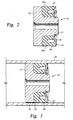
- Figure 3 is a cross sectional view of the sealing member of Figure 2 mounted on a piston head in a cylinder.
- Referring initially to Figure 1, a typical prior-art mud pump piston assembly comprises a
piston head 10 and a sealing device orseal 15 therefor slidably received in apiston cylinder 12.Piston head 10 comprises a generally cylindrical body having aflange 11 extending therefrom. Pistonhead 10 is typically made of steel, such as AISI 4140.Seal 15 is friction fit onpiston head 10 andabuts flange 11.Seal 15 comprises anelastomeric sealing section 14 and aheel section 13. These sections are either integrally formed or bonded together.Heel section 13 is typically made from a stack of several layers of rubber-impregnated fabric, which give it a higher modulus of elasticity than theelastomeric sealing section 14. In prior art mud pumps, theheel section 13, which is stiffer than the elastomeric sealing section, resists extrusion into the gap between the cylinder and piston flange to some extent. However,heel section 13 is still forced into the gap under the influence of the hydrostatic pressure in locations where wear occurs.Reference numeral 18 designates a portion ofheel section 14 that has been extruded into thegap 20 between theflange 11 and thecylinder 12. - Both
elastomeric sealing section 14 andheel section 13 make intimate contact with thecylinder 12. Seal 15 is held in place by aretaining ring 16 and asnap ring 17, which holdseal 15 in place and permit replacement thereof. Easy replacement of seals is a desirable feature for a mud pump, since seals typically wear out long before the other mud pump components and must be replaced in order to continue pumping operations. - The direction of travel of
piston 10 is shown byarrow 19. The direction of the hydrostatic pressure force exerted by the working fluid of the pump is shown byarrows 21. This force axially compresseselastomeric sealing section 14 andheel section 13 and radially expands these sections against the cylinder wall. - Referring now to Figure 2, a
seal 22 constructed in accordance with the present invention is shown. In Figures 2 and 3, items corresponding to items in Figure 1 are assigned the same reference numerals.Seal 22 includes aheel 23 and anelastomeric sealing lip 24.Seal 22 is preferably formed in one piece, so thatelastomeric sealing lip 24 is integral withheel section 23. According to the preferred embodiment,seal 22 is preferably formed from a rigid polymer having the properties set out in the following Table.Hardness, Shore A: >80 E50 Modulus: >900 psi (approx. 6 MPa) E100 Modulus: >1000 psi (approx. 7 MPa) E200 Modulus: >1500 psi (approx. 10 MPa) E300 Modulus: >2000 psi (approx. 14 MPa) Ultimate Tensile Strength: >5000 psi (approx. 35 MPa) Ultimate Elongation: > 350 % Tear, C: > 500 pli (approx. 88 kN/m) - Also, because it is used in a wet environment,
seal 22 is preferably made from a material that is resistant to degradation by water. Therefore, it is preferred that the material not exhibit significant reductions in the aforementioned properties after prolonged exposure to water. An example of a preferred polymer is a polyurethane, such as that sold by Utex Industries under the identifier 50399. - Referring now to Figure 3, the
seal 22 of Figure 2 is shown mounted on a piston head in a cylinder. It can be seen that sealinglip 24 is compressed radially and conforms to the inside ofcylinder 12. In addition, in order to enableseal 22 to be used without a reinforced heel section,piston head 10 is manufactured to extremely tight tolerances. In particular, it has been discovered that the life ofseal 22 can be greatly prolonged by ensuring that play betweenflange 11 andcylinder 12 is minimized at the outset. Thus, the average width of theannular gap 25 betweenflange 11 andcylinder 12 is much smaller than in previously known devices. In this regard, it is preferred that the difference between the outside diameter offlange 11 as manufactured and the inside diameter ofcylinder 12 as manufactured be less than 0.010 inches (approx. 0.25mm), and more preferably less than 0.008 inches (approx. 0.2mm). By way of example,flange 11 of a 6 inch (approx. 15cm) piston is preferably about 0.002 to 0.010 inch (approx. 0.05 to 0.25mm) smaller than the associated bore. - As can be seen in the Figures, the sealing
lip 24 ofseal 22 is preferably somewhat larger than the nominal inside diameter of thecylinder 12. Again by way of example, for a piston having a nominal diameter of six inches (approx. 15cm), sealinglip 24 preferably has a diameter of about 6.25 inches (approx. 15.9cm). Thus, in one preferred embodiment, diameters are as follows: formetal flange 11, df = 5.990" (approx. 15.21cm); forcylinder 12, inside diameter id1 = 6.000" (approx. 15.24cm); forseal lip 23, ds = 6.250" (approx. 15.88cm); and forheel 24, dh = 5.990" (approx. 15.2cm). - It is preferred that
seal lip 24 be at least about 0.20 inches (approx. 5.1mm), and more preferably at least about 0.25 inches (approx. 6.35mm), larger in diameter than the inside diameter ofcylinder 12. This ensures thatseal lip 24 is compressed when positioned incylinder 12. The degree of compression will decrease asseal 22 becomes worn, so it is desirable to have a fairly high degree of compression on a new (unworn) seal. Also, as the liner itself wears, the high degree of designed compression in the nominal seal size will compensate, thus allowing the whole system to seal effectively for longer periods of wear. As shown in the Figures, onlylip 24 is oversized. Behindlip 24, the body ofseal 22 tapers down to the nominal 6.000" diameter (approx. 15.24cm). According to the preferred embodiment, by manufacturingseal 22 andflange 11 to very close tolerances and very precise symmetry, the destructive effect of extrusion onseal 22 is significantly decreased. - It has further been discovered that prior art seals suffer from having a slight depression around the circumference around their outside surfaces. This depression is exaggerated and shown in phantom as indicated by numeral 14a in Figure 1. It has been found that
manufacturing seal 22 in such a way as to eliminate this depression enhances the life ofseal 22.Depression 14a can be eliminated by shaping the mold in which it is formed so as to compensate for the shrinkage that occurs when the seal is demolded, or by machining the outside surface of the seal after demolding. The former of these two techniques is preferred for cost reasons. In cases where the mold shape is modified, the uncured shape ofseal 22 has a larger diameter than the ultimate desired shape, as shown in phantom at 23a in Figure 2. Other, alternative techniques for achieving this objective will also be known to those skilled in the art. In a preferred approach,heel 24 includes anannular bulge 23a when it is first molded. Whenannular seal 22 is removed from the mold and allowed to cure, shrinkage of the material causesbulge 23a to disappear. - Although the invention is described with particular reference to a pump piston used with slush or mud pumps, it will be recognized that certain features thereof may be used or adopted to use in other types of reciprocating pumps. Likewise it will be understood that various modification can be made to the present seal without departing from the scope of the invention, which is defined in the appended claims. For example, the materials from which the seal is made can be varied, so long as the seal retains the advantages discussed herein.
Claims (15)
- In combination, a cylinder (12) and a piston head assembly (10) for a mud pump, the piston head assembly (10) being reciprocatingly movable in the cylinder (12), said cylinder (12) having an inside surface having an inside diameter, the piston head assembly (10) comprising:a piston head (10) including a central portion and a flange (11); and,an annular seal (22) removably mounted on said flange (11), the seal (22) including a lip (24) and a heel (23); characterised by:said heel (23) being free of a separate reinforcement means;said flange (11) having a diameter that is no more than 0.010 inches (approx. 0.25mm) less than said inside diameter of said inside surface of the cylinder (12) when new; and,said lip (24) having an uncompressed diameter that is at least 0.20 inches (approx. 5.1 mm) larger than said inside diameter of said inside surface of the cylinder (12).
- A combination according to claim 1, wherein said flange diameter is no more than 0.008 inches (approx. 0.2mm) less than said inside diameter when new.
- A combination according to claim 1, wherein said flange diameter is no more than 0.005 inches (approx. 0.13mm) less than said inside diameter when new.
- A combination according to any of claims 1 to 3, wherein said annular seal (22) comprises a polyurethane.
- A combination according to any of claims 1 to 4, wherein said annular seal (22) comprises a material having a hardness of at least 80 Shore A.
- A combination according to any of claims 1 to 5, wherein said annular seal (22) comprises a material having a hardness of at least 80 Shore A after prolonged exposure to water.
- A combination according to any of claims 1 to 6, wherein said heel (23) of said annular seal (22) includes an annular bulge (23a) as molded.
- A combination according to any of claims 1 to 6, wherein said heel (23) has been machined to attain a substantially cylindrical shape that is free of any annular depression.
- A method for making a piston head assembly (10) for reciprocating in a cylinder (12) that has an inside surface having an inside diameter, the method comprising:providing a piston head (10) including a central portion and a flange (11) wherein the flange (11) has a diameter that is no more than 0.010 inches (approx. 0.25mm) less than said inside diameter of said inside surface of the cylinder (12);mounting a removable annular seal (22) on the flange (11) wherein the seal (22) includes a lip (24) and a heel (23), the lip (24) having an uncompressed diameter that is at least 0.20 inches (approx. 5.1 mm) larger than said inside diameter of said inside surface of the cylinder (12), and the heel (23) being free of a separate retaining means.
- A method according to claim 9, further including the steps of manufacturing the annular seal (22) with a bulge (23a) in its outer surface and eliminating the bulge (23a) prior to placing the seal (22) in the cylinder (12).
- A method according to claim 10, wherein the bulge (23a) is eliminated by designed shrinkage of the seal (22).
- A method according to claim 10, wherein the bulge (23a) is eliminated by machining.
- A method according to any of claims 9 to 12, wherein the flange diameter is no more than 0.008 (approx. 0.2mm) inches less than the inside diameter.
- A method according to any of claims 9 to 12, wherein the flange diameter is no more than 0.005 inches (approx. 0.13mm) less than the inside diameter.
- A method according to any of claims 9 to 14, wherein the annular seal (22) comprises a polyurethane.
Applications Claiming Priority (3)
| Application Number | Priority Date | Filing Date | Title |
|---|---|---|---|
| US09/141,173 US5960700A (en) | 1998-08-26 | 1998-08-26 | Replaceable mud pump piston seal |
| US141173 | 1998-08-26 | ||
| PCT/US1999/015746 WO2000012919A1 (en) | 1998-08-26 | 1999-07-13 | Replaceable mud pump piston seal |
Publications (3)
| Publication Number | Publication Date |
|---|---|
| EP1108170A1 EP1108170A1 (en) | 2001-06-20 |
| EP1108170A4 EP1108170A4 (en) | 2004-07-14 |
| EP1108170B1 true EP1108170B1 (en) | 2007-06-13 |
Family
ID=22494505
Family Applications (1)
| Application Number | Title | Priority Date | Filing Date |
|---|---|---|---|
| EP99933930A Expired - Lifetime EP1108170B1 (en) | 1998-08-26 | 1999-07-13 | Replaceable mud pump piston seal |
Country Status (6)
| Country | Link |
|---|---|
| US (1) | US5960700A (en) |
| EP (1) | EP1108170B1 (en) |
| BR (1) | BR9913246A (en) |
| CA (1) | CA2341242C (en) |
| DE (1) | DE69936310T2 (en) |
| WO (1) | WO2000012919A1 (en) |
Families Citing this family (26)
| Publication number | Priority date | Publication date | Assignee | Title |
|---|---|---|---|---|
| US6511493B1 (en) | 2000-01-10 | 2003-01-28 | Hydrocision, Inc. | Liquid jet-powered surgical instruments |
| DE60221239T2 (en) | 2001-04-27 | 2008-04-10 | HydroCision, Inc., Billerica | HIGH PRESSURE PUMP CARTRIDGE FOR USE IN THE MEDICAL FIELD |
| CA2450432C (en) * | 2001-06-12 | 2007-12-04 | Utex Industries, Inc. | Packing assembly for rotary drilling swivels |
| US6923792B2 (en) | 2001-08-08 | 2005-08-02 | Hydrocision, Inc. | Medical device with high pressure quick disconnect handpiece |
| US20030184019A1 (en) | 2002-04-02 | 2003-10-02 | Rimmer Ian Douglas | Method and apparatus for injecting packing into stuffing boxes for reciprocating rods |
| CN100445562C (en) * | 2003-08-29 | 2008-12-24 | 陈勇 | Well drilling pump piston |
| WO2007044080A2 (en) * | 2005-10-06 | 2007-04-19 | American Seal And Engineering Company, Inc. | Volumetric sealing system |
| US20070261888A1 (en) * | 2006-04-29 | 2007-11-15 | Richard Urquhart | Mud pump systems for drilling operations |
| US8561523B2 (en) * | 2007-04-23 | 2013-10-22 | National Oilwell Varco, L.P. | Reciprocating pump having a piston assembly |
| US8025487B1 (en) | 2007-08-20 | 2011-09-27 | Paul Iii William | Rod arm baffle apparatus |
| US20090166980A1 (en) * | 2008-01-02 | 2009-07-02 | Miller John A | Packing assembly for a pump |
| DE102008017035A1 (en) * | 2008-04-03 | 2009-10-08 | Gustav Magenwirth Gmbh & Co. Kg | Device for sealing a hydraulic piston |
| US8061445B2 (en) * | 2008-08-13 | 2011-11-22 | National Oilwell Varco L.P. | Drilling fluid pump systems and methods |
| USD631492S1 (en) | 2008-08-13 | 2011-01-25 | Ronald William Yater | Module for drilling fluid pump system |
| US9328729B2 (en) | 2008-10-16 | 2016-05-03 | National Oilwell Varco, L.P. | Pumping systems with dedicated surge dampeners |
| US20100098568A1 (en) | 2008-10-16 | 2010-04-22 | Adrian Marica | Mud pump systems for wellbore operations |
| US8827242B2 (en) | 2008-10-16 | 2014-09-09 | National Oilwell Varco, L.P. | Valve cartridge for pump systems |
| US8757592B2 (en) * | 2008-10-16 | 2014-06-24 | National Oilwell Varco, L.P. | Poppet valve for pump systems with non-rigid connector to facilitate effective sealing |
| JP6327933B2 (en) * | 2013-06-28 | 2018-05-23 | 株式会社クレハ | Rubber member for downhole tool, downhole tool, and hydrocarbon resource recovery method |
| BR112016002066B1 (en) | 2013-08-20 | 2021-09-21 | Dow Global Technologies Llc | METHOD FOR FORMING A PISTON SEAL OF A HYDRAULIC PUMP AND HYDRAULIC PUMP |
| DE102013223364A1 (en) * | 2013-11-15 | 2015-05-21 | Heinrich Frey Maschinenbau Gmbh | filling device |
| US10724516B2 (en) | 2017-06-13 | 2020-07-28 | Forum Us, Inc. | Reciprocating piston |
| USD893684S1 (en) | 2017-08-22 | 2020-08-18 | Garlock Sealing Technologies, Llc | Header ring for a reciprocating stem or piston rod |
| US11143305B1 (en) | 2017-08-22 | 2021-10-12 | Garlock Sealing Technologies, Llc | Hydraulic components and methods of manufacturing |
| US12007028B2 (en) * | 2017-12-08 | 2024-06-11 | Nordson Corporation | Bulk unloader follower seal |
| JP7082675B2 (en) * | 2018-02-12 | 2022-06-08 | 恵州海卓科賽医療有限公司 | Elastic piston and high pressure pumping system |
Family Cites Families (29)
| Publication number | Priority date | Publication date | Assignee | Title |
|---|---|---|---|---|
| US2196337A (en) * | 1937-01-08 | 1940-04-09 | Hydraulic Brake Co | Flexible cup |
| US2741518A (en) * | 1953-03-10 | 1956-04-10 | Arthur L Leman | Reciprocating pump piston and rod connection |
| US2840426A (en) * | 1954-08-16 | 1958-06-24 | Technica Establishment | Piston packings |
| US2861851A (en) * | 1956-01-30 | 1958-11-25 | Mission Mfg Co | Piston and rod assemblies |
| US2987354A (en) * | 1959-05-22 | 1961-06-06 | American Iron & Machine Works | Pump piston |
| US3038768A (en) * | 1959-09-08 | 1962-06-12 | Mcneil Machine & Eng Co | Lubricant-gun follower packing |
| US3131611A (en) * | 1962-11-14 | 1964-05-05 | Mission Mfg Co | Taper cup back piston |
| US3232186A (en) * | 1964-03-16 | 1966-02-01 | Drilco Oil Tools Inc | Piston and rod |
| US3388638A (en) * | 1966-03-02 | 1968-06-18 | Ross Operating Valve Co | Piston |
| FR2246204A5 (en) * | 1973-09-28 | 1975-04-25 | Secmafer Sa | |
| US4143586A (en) * | 1975-10-28 | 1979-03-13 | Poly-Seal | Mud pump piston |
| US4147824A (en) * | 1976-03-31 | 1979-04-03 | Burkert Gmbh | Multilayer seals and method for their production and joining to seal carriers |
| JPS598036Y2 (en) * | 1977-08-20 | 1984-03-12 | トキコ株式会社 | cylinder device |
| US4281590A (en) * | 1979-01-02 | 1981-08-04 | Weaver Joe T | Piston construction for reciprocating pumps |
| US4242057A (en) * | 1979-09-24 | 1980-12-30 | Bender Emil A | Tandem long stroke reciprocating mud pump assembly |
| US4317409A (en) * | 1980-03-03 | 1982-03-02 | Bottoms Clifford C | Mud pump piston assembly |
| US4380951A (en) * | 1980-03-03 | 1983-04-26 | Bottoms Clifford C | Mud pump piston assembly |
| US4459899A (en) * | 1980-04-08 | 1984-07-17 | Richardson Murl R | Single acting reciprocating pump piston |
| US4346647A (en) * | 1981-02-20 | 1982-08-31 | Weaver Manufacturing Company | Piston construction for reciprocating pumps |
| US4676724A (en) * | 1981-10-08 | 1987-06-30 | Birdwell J C | Mud pump |
| US4516785A (en) * | 1982-12-10 | 1985-05-14 | Chromium Corporation | Piston with a controlled expansion piston anti-extrusion ring |
| US4735129A (en) * | 1983-06-03 | 1988-04-05 | Chromium Corporation | Single acting mud pump piston |
| US4858516A (en) * | 1983-06-29 | 1989-08-22 | Alfred Teves Gmbh | Brake cylinder-piston slave unit seal having radial roll-back protrusion for piston spring back retract |
| US4601235A (en) * | 1984-06-18 | 1986-07-22 | Trw Inc. | Reciprocating pump piston |
| US4596395A (en) * | 1984-11-13 | 1986-06-24 | Utex Industries, Inc. | Dual material lip-type seal |
| US5284084A (en) * | 1991-01-17 | 1994-02-08 | Utex Industries, Inc. | Light weight piston |
| US5480163A (en) * | 1993-08-05 | 1996-01-02 | Utex Industries, Inc. | Lip seal with reinforced backup |
| US5480164A (en) * | 1994-11-23 | 1996-01-02 | Murphy; William G. | Dead length collet chuck holder |
| US5735188A (en) * | 1996-06-04 | 1998-04-07 | Automotive Products (Usa), Inc. | External slave cylinder for hydraulic clutch release system |
-
1998
- 1998-08-26 US US09/141,173 patent/US5960700A/en not_active Expired - Lifetime
-
1999
- 1999-07-13 BR BR9913246-0A patent/BR9913246A/en not_active IP Right Cessation
- 1999-07-13 DE DE69936310T patent/DE69936310T2/en not_active Expired - Lifetime
- 1999-07-13 EP EP99933930A patent/EP1108170B1/en not_active Expired - Lifetime
- 1999-07-13 WO PCT/US1999/015746 patent/WO2000012919A1/en not_active Ceased
- 1999-07-13 CA CA002341242A patent/CA2341242C/en not_active Expired - Lifetime
Also Published As
| Publication number | Publication date |
|---|---|
| DE69936310T2 (en) | 2008-02-07 |
| DE69936310D1 (en) | 2007-07-26 |
| EP1108170A1 (en) | 2001-06-20 |
| WO2000012919A8 (en) | 2000-06-08 |
| CA2341242C (en) | 2008-02-26 |
| CA2341242A1 (en) | 2000-03-09 |
| WO2000012919A1 (en) | 2000-03-09 |
| BR9913246A (en) | 2001-05-22 |
| EP1108170A4 (en) | 2004-07-14 |
| US5960700A (en) | 1999-10-05 |
Similar Documents
| Publication | Publication Date | Title |
|---|---|---|
| US5960700A (en) | Replaceable mud pump piston seal | |
| US8312805B1 (en) | High pressure pump piston | |
| US5028056A (en) | Fiber composite sealing element | |
| US6290235B1 (en) | Sealing system for a reciprocating shaft | |
| US6957605B1 (en) | High pressure pump piston | |
| EP2253870B1 (en) | Seal assembly | |
| EP0961891B1 (en) | Unidirectional rod sealing ring for a hydraulic cylinder | |
| CA1228879A (en) | Packing arrangement | |
| US4067584A (en) | Guiding and sealing arrangements for pistons, piston rods and the like | |
| EP0237672A2 (en) | Seal | |
| EP0171892A2 (en) | Reciprocating pump piston | |
| EP0871828A1 (en) | Extrusion resistant hydrodynamically lubricated multiple modulus rotary shaft seal | |
| EP0713035B1 (en) | Self-venting seal assembly | |
| US4516785A (en) | Piston with a controlled expansion piston anti-extrusion ring | |
| KR20000064806A (en) | Compact 5-Ring Stuffing Box Packing Assembly | |
| EP1152177A3 (en) | Lip seal | |
| CA2127944A1 (en) | Lip seal with reinforced backup | |
| WO1994009296A1 (en) | Composite radial seal | |
| WO2005121613A1 (en) | Sealing system | |
| US2926976A (en) | Pistons and sealing elements therefor | |
| US3131611A (en) | Taper cup back piston | |
| US4735129A (en) | Single acting mud pump piston | |
| US6092809A (en) | Secondary seal for a sealing arrangement | |
| CN111433494A (en) | Ring Dust Seal | |
| US2918336A (en) | Piston |
Legal Events
| Date | Code | Title | Description |
|---|---|---|---|
| PUAI | Public reference made under article 153(3) epc to a published international application that has entered the european phase |
Free format text: ORIGINAL CODE: 0009012 |
|
| 17P | Request for examination filed |
Effective date: 20010228 |
|
| AK | Designated contracting states |
Kind code of ref document: A1 Designated state(s): AT BE CH CY DE DK ES FI FR GB GR IE IT LI LU MC NL PT SE |
|
| RBV | Designated contracting states (corrected) |
Designated state(s): DE FR GB NL |
|
| A4 | Supplementary search report drawn up and despatched |
Effective date: 20040601 |
|
| RIC1 | Information provided on ipc code assigned before grant |
Ipc: 7F 04B 53/14 B Ipc: 7F 16J 9/00 A |
|
| GRAP | Despatch of communication of intention to grant a patent |
Free format text: ORIGINAL CODE: EPIDOSNIGR1 |
|
| GRAS | Grant fee paid |
Free format text: ORIGINAL CODE: EPIDOSNIGR3 |
|
| GRAA | (expected) grant |
Free format text: ORIGINAL CODE: 0009210 |
|
| AK | Designated contracting states |
Kind code of ref document: B1 Designated state(s): DE FR GB NL |
|
| REG | Reference to a national code |
Ref country code: GB Ref legal event code: FG4D |
|
| REF | Corresponds to: |
Ref document number: 69936310 Country of ref document: DE Date of ref document: 20070726 Kind code of ref document: P |
|
| ET | Fr: translation filed | ||
| PLBE | No opposition filed within time limit |
Free format text: ORIGINAL CODE: 0009261 |
|
| STAA | Information on the status of an ep patent application or granted ep patent |
Free format text: STATUS: NO OPPOSITION FILED WITHIN TIME LIMIT |
|
| 26N | No opposition filed |
Effective date: 20080314 |
|
| PGFP | Annual fee paid to national office [announced via postgrant information from national office to epo] |
Ref country code: FR Payment date: 20090717 Year of fee payment: 11 |
|
| REG | Reference to a national code |
Ref country code: FR Ref legal event code: ST Effective date: 20110331 |
|
| PG25 | Lapsed in a contracting state [announced via postgrant information from national office to epo] |
Ref country code: FR Free format text: LAPSE BECAUSE OF NON-PAYMENT OF DUE FEES Effective date: 20100802 |
|
| PGFP | Annual fee paid to national office [announced via postgrant information from national office to epo] |
Ref country code: DE Payment date: 20180703 Year of fee payment: 20 Ref country code: NL Payment date: 20180712 Year of fee payment: 20 |
|
| PGFP | Annual fee paid to national office [announced via postgrant information from national office to epo] |
Ref country code: GB Payment date: 20180711 Year of fee payment: 20 |
|
| REG | Reference to a national code |
Ref country code: DE Ref legal event code: R071 Ref document number: 69936310 Country of ref document: DE |
|
| REG | Reference to a national code |
Ref country code: NL Ref legal event code: MK Effective date: 20190712 |
|
| REG | Reference to a national code |
Ref country code: GB Ref legal event code: PE20 Expiry date: 20190712 |
|
| PG25 | Lapsed in a contracting state [announced via postgrant information from national office to epo] |
Ref country code: GB Free format text: LAPSE BECAUSE OF EXPIRATION OF PROTECTION Effective date: 20190712 |