EP1107911B1 - Apparatus for handling and packaging friable tablets - Google Patents
Apparatus for handling and packaging friable tablets Download PDFInfo
- Publication number
- EP1107911B1 EP1107911B1 EP99914893A EP99914893A EP1107911B1 EP 1107911 B1 EP1107911 B1 EP 1107911B1 EP 99914893 A EP99914893 A EP 99914893A EP 99914893 A EP99914893 A EP 99914893A EP 1107911 B1 EP1107911 B1 EP 1107911B1
- Authority
- EP
- European Patent Office
- Prior art keywords
- dosage forms
- laning
- tablets
- assembly
- dump gate
- Prior art date
- Legal status (The legal status is an assumption and is not a legal conclusion. Google has not performed a legal analysis and makes no representation as to the accuracy of the status listed.)
- Expired - Lifetime
Links
- 238000004806 packaging method and process Methods 0.000 title claims abstract description 39
- 239000002552 dosage form Substances 0.000 claims abstract description 72
- 239000005022 packaging material Substances 0.000 claims description 21
- 238000007789 sealing Methods 0.000 abstract description 24
- 230000032258 transport Effects 0.000 abstract description 6
- 239000000463 material Substances 0.000 description 12
- 230000006378 damage Effects 0.000 description 3
- 230000008901 benefit Effects 0.000 description 2
- 238000010438 heat treatment Methods 0.000 description 2
- 239000004033 plastic Substances 0.000 description 2
- 229920003023 plastic Polymers 0.000 description 2
- 239000007787 solid Substances 0.000 description 2
- 230000007704 transition Effects 0.000 description 2
- 238000011144 upstream manufacturing Methods 0.000 description 2
- 229910000831 Steel Inorganic materials 0.000 description 1
- 239000004809 Teflon Substances 0.000 description 1
- 229920006362 Teflon® Polymers 0.000 description 1
- 238000009825 accumulation Methods 0.000 description 1
- 239000004480 active ingredient Substances 0.000 description 1
- 229910052782 aluminium Inorganic materials 0.000 description 1
- XAGFODPZIPBFFR-UHFFFAOYSA-N aluminium Chemical compound [Al] XAGFODPZIPBFFR-UHFFFAOYSA-N 0.000 description 1
- 230000000712 assembly Effects 0.000 description 1
- 238000000429 assembly Methods 0.000 description 1
- 239000002775 capsule Substances 0.000 description 1
- 238000001514 detection method Methods 0.000 description 1
- 239000003814 drug Substances 0.000 description 1
- 239000000428 dust Substances 0.000 description 1
- 230000000694 effects Effects 0.000 description 1
- 229920001971 elastomer Polymers 0.000 description 1
- 229920002313 fluoropolymer Polymers 0.000 description 1
- 239000004811 fluoropolymer Substances 0.000 description 1
- 239000011888 foil Substances 0.000 description 1
- 229910052751 metal Inorganic materials 0.000 description 1
- 239000002184 metal Substances 0.000 description 1
- 150000002739 metals Chemical class 0.000 description 1
- 239000000203 mixture Substances 0.000 description 1
- 239000008188 pellet Substances 0.000 description 1
- 239000006187 pill Substances 0.000 description 1
- 239000012858 resilient material Substances 0.000 description 1
- 230000004044 response Effects 0.000 description 1
- 229920002379 silicone rubber Polymers 0.000 description 1
- 239000004945 silicone rubber Substances 0.000 description 1
- 239000010959 steel Substances 0.000 description 1
- 239000003826 tablet Substances 0.000 description 1
- BFKJFAAPBSQJPD-UHFFFAOYSA-N tetrafluoroethene Chemical compound FC(F)=C(F)F BFKJFAAPBSQJPD-UHFFFAOYSA-N 0.000 description 1
- 230000000007 visual effect Effects 0.000 description 1
Images





Classifications
-
- B—PERFORMING OPERATIONS; TRANSPORTING
- B65—CONVEYING; PACKING; STORING; HANDLING THIN OR FILAMENTARY MATERIAL
- B65B—MACHINES, APPARATUS OR DEVICES FOR, OR METHODS OF, PACKAGING ARTICLES OR MATERIALS; UNPACKING
- B65B5/00—Packaging individual articles in containers or receptacles, e.g. bags, sacks, boxes, cartons, cans, jars
- B65B5/10—Filling containers or receptacles progressively or in stages by introducing successive articles, or layers of articles
- B65B5/101—Filling containers or receptacles progressively or in stages by introducing successive articles, or layers of articles by gravity
- B65B5/103—Filling containers or receptacles progressively or in stages by introducing successive articles, or layers of articles by gravity for packaging pills or tablets
-
- B—PERFORMING OPERATIONS; TRANSPORTING
- B65—CONVEYING; PACKING; STORING; HANDLING THIN OR FILAMENTARY MATERIAL
- B65B—MACHINES, APPARATUS OR DEVICES FOR, OR METHODS OF, PACKAGING ARTICLES OR MATERIALS; UNPACKING
- B65B11/00—Wrapping, e.g. partially or wholly enclosing, articles or quantities of material, in strips, sheets or blanks, of flexible material
- B65B11/50—Enclosing articles, or quantities of material, by disposing contents between two sheets, e.g. pocketed sheets, and securing their opposed free margins
-
- B—PERFORMING OPERATIONS; TRANSPORTING
- B65—CONVEYING; PACKING; STORING; HANDLING THIN OR FILAMENTARY MATERIAL
- B65B—MACHINES, APPARATUS OR DEVICES FOR, OR METHODS OF, PACKAGING ARTICLES OR MATERIALS; UNPACKING
- B65B35/00—Supplying, feeding, arranging or orientating articles to be packaged
- B65B35/30—Arranging and feeding articles in groups
-
- B—PERFORMING OPERATIONS; TRANSPORTING
- B65—CONVEYING; PACKING; STORING; HANDLING THIN OR FILAMENTARY MATERIAL
- B65B—MACHINES, APPARATUS OR DEVICES FOR, OR METHODS OF, PACKAGING ARTICLES OR MATERIALS; UNPACKING
- B65B35/00—Supplying, feeding, arranging or orientating articles to be packaged
- B65B35/30—Arranging and feeding articles in groups
- B65B35/36—Arranging and feeding articles in groups by grippers
- B65B35/38—Arranging and feeding articles in groups by grippers by suction-operated grippers
-
- B—PERFORMING OPERATIONS; TRANSPORTING
- B65—CONVEYING; PACKING; STORING; HANDLING THIN OR FILAMENTARY MATERIAL
- B65B—MACHINES, APPARATUS OR DEVICES FOR, OR METHODS OF, PACKAGING ARTICLES OR MATERIALS; UNPACKING
- B65B35/00—Supplying, feeding, arranging or orientating articles to be packaged
- B65B35/30—Arranging and feeding articles in groups
- B65B35/44—Arranging and feeding articles in groups by endless belts or chains
Definitions
- the present invention relates to an apparatus for handling and packaging pharmaceutical dosage forms, particularly fragile dosage forms.
- the present invention can be applied to systems or assemblies for packaging essentially any dosage form.
- Such systems may include a forming device such as a tablet press, an infeed structure, a laning structure, robotic devices for handling or carrying dosage forms, and a packaging machine.
- a series of conveyor belts and ramps transport the dosage forms through the packaging system. After the dosage forms are made, they proceed through the system and are controlled and organized for receipt by a packaging machine.
- a robotic handler may be used to transport dosage forms to the packaging machine. If the system packages dosage forms into blister packages, a robotic handler may be used to transport dosage forms to a sheet of packaging material, which will be sealed with a second sheet of material to form packages of the dosage forms.
- the dosage forms travel through the packaging system rapidly and in large volumes. As many as 800 to 1,440 tablets per minute, or more, may be assembled into 240 packages of tablets per minute, or more. Hence, a displaced machine part, one of the dosage forms, or other debris anywhere in the system can cause dosage forms to break and improperly formed packages. Some systems must be shut down so that the jammed product or other debris may be cleared manually. This results in a loss of the product in large numbers before the system can be interrupted and the problem remedied.
- An assembly for handling and packaging pharmaceutical dosage forms in accordance with the preamble of claim 1 is known from DE-A-44 06 089.
- the assembly comprises an infeed portion having a movable surface in cooperation with a laterally extending laning structure.
- a series of transverse stop-gates are provided in cooperation with lanes of the laning structure.
- a handling means and packaging means are provided at an exit end of the laning structure.
- the present invention addresses these needs.
- the assembly in accordance with this aspect includes an infeed structure for accepting a series of dosage forms including a surface movable in a downstream direction, a laning structure defining a plurality of lanes extending in the downstream direction and having a downstream end, and a plenum structure extending from the infeed structure to the laning structure, including a guide portion for guiding dosage forms carried by said surface into the laning structure.
- a form handling device is provided for receiving dosage forms and transporting dosage forms from the laning structure to a packaging device.
- a dump gate has a closed position in which the dump gate blocks the lanes at the downstream ends of the lanes. In the closed position, dosage forms will accumulate in the lanes.
- the dump gate also has an open position in which the dump gate does not block the lanes.
- a timed controller is provided for opening the dump gate after the handling device receives dosage forms so that debris will be carried downstream out of the laning structure after the form handling device receives dosage forms from the laning structure.
- This aspect of the invention provides a dosage form handling assembly which clears the laning structure of debris without excessive loss of undamaged dosage forms.
- the timed controller is preferably arranged so that debris is carried out of the laning structure and the dump gate is brought into its closed position before undamaged tablets escape the laning structure.
- the timed controller preferably comprises a computer communicating with the form handling device and the dump gate.
- a guide wall structure defines the guide portion which preferably includes a curved portion.
- the guide wall structure also preferably defines the plenum structure which preferably includes a plenum entry.
- the guide wall structure is shaped to guide dosage forms entering the plenum structure so that the dosage forms enter the plenum entry adjacent a first side of the laning structure and travel in a first direction transverse to the downstream direction toward a second side of the laning structure before entering the lanes of the laning structure.
- the curved portion of the guide wall structure includes a member adjacent the plenum entry.
- a biasing means or biasing device is provided in certain preferred embodiments for vibrating the member to agitate the dosage forms and relieve jamming of dosage forms.
- the biasing means may comprise a shaker for vibrating the member.
- the guide wall structure and moveable member is provided to guide fragile dosage forms from the infeed structure to the laning structure for organizing the dosage forms to be placed into packages.
- the transition between the infeed structure and the laning structure in this aspect of the invention is shaped to prevent jamming or a bottleneck effect in this transitional area which may result in damage to or destruction of the dosage forms.
- the laning structure preferably includes a surface for supporting the dosage forms. This surface, in certain preferred embodiments, slopes in the downstream direction to the dump gate so that debris is carried out of the laning structure when the dump gate is in the open position.
- At least one of the top plate and bottom plate is comprised of a plurality of blocks and a base for supporting the plurality of blocks thereon.
- the blocks are floatably supported by the base and individually moveable with respect to the base so that pressure applied to the package material and the lid stock by the top and bottom plates is evenly distributed.
- This aspect of the invention provides a more evenly and more reliably sealed package.
- each of the blocks is free to tilt relative to the base in all directions.
- the base may include a ball-like member for each block and each block may include a corresponding circular cavity formed at a second surface of each block opposite to the first surface on which the packaging material is engaged. The cavity receives the ball-like member so that the block is floatably supported by the base.
- either the top plate, the bottom plate or both are heated for sealing the package material and the lid stock together to form a package for the dosage form.
- Another preferred embodiment of the invention provides an assembly for guiding pharmaceutical dosage forms in a packaging assembly, comprising a surface movable in a downstream direction, a laning structure extending in a lateral direction transverse to the downstream direction and defining a plurality of laterally spaced lanes extending in the downstream direction.
- the assembly also comprises guide wall structures including a curved portion and a wall structure defining a plenum upstream of the laning structure.
- the curved portion guides the dosage forms carried by said surface so that dosage forms enter the plenum structure at a plenum entry adjacent a first side of the laning structure and travel laterally toward a second side of the laning structure before entering the lanes.
- the assembly preferably includes a form handling device for receiving dosage forms and transporting dosage forms from the laning structure to a packaging device.
- the packaging device may include a top plate and a bottom plate for engaging a packaging material and a lid stock therebetween to seal the packaging material and lid stock together, forming packaged dosage forms.
- the assembly may include a top plate and bottom plate including a plurality of blocks and a base for floatably supporting the blocks.
- the lanes may have a downstream end and the assembly may further comprise a dump gate at the downstream end, having an open position and a closed position.
- a timed controller may be provided for opening the dump gate after the handling device receives dosage forms so that debris will be carried downstream out of the laning structure.
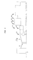
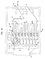
- FIG. 1-9 One embodiment of an assembly for handling and packaging dosage forms in accordance with the invention is depicted in Figs. 1-9.
- An infeed structure 22, a laning structure 35 and a plenum structure 32 extending between the infeed structure and the laning structure arrange dosage forms such as tablets into rows so that they can be arranged into packages.
- the dosage forms handled by the assembly may be any type of dosage form, including tablets, capsules, pills, pellets, and other forms.
- the assembly is particularly useful for fragile dosage forms.
- the tablets are transported throughout the assembly on a movable surface or conveyance device, such as a conventional conveyor belt.
- a rotating drum or disk may also be used.
- the conveyor belt is driven by any conventional means 13 such as an electric motor or other conventional drive so that the upper run 10 of the belt moves in a downstream direction 11.
- the motor is controlled by a switch and a control device for starting and stopping the conveyor belt and varying the speed of the conveyor belt.
- the conveyor belt is adjacent a tablet press 12 which forms tablets 15.
- the tablets travel from the tablet press down a ramp 21 to the conveyor belt.
- the ramps, as well as the other surfaces used in the assembly which contact the tablets are preferably made of a smooth material which will not interfere with the sliding of the tablets to the next stage of the system. Many plastics and other materials may be used.
- the ramps and other surfaces may be coated with a smooth material such as a fluoropolymer of the type sold under the trademark TEFLON to promote the sliding of the tablets.
- the upper run 10 of the belt receives tablets 15 from the tablet press 12 and conveys the tablets in the downstream direction 11.
- the infeed structure 22 includes a guide wall structure 14 is disposed over the upper run 10 of the conveyor belt, and guides the tablets as they move downstream with the belt.
- the speed of the conveyor belt is variable in a range from about 12.192-30.48 m/min (40 to 100 feet per minute).
- the guide wall structure 14 defines a channel 20 over the upper run 10 of the belt extending from the tablet press to the laning structure.
- the channel 20 has a top wall 17, a first side wall 18, a second sidewall 19 and an open bottom 16, as shown in Fig. 5.
- the open bottom 16 of the channel 20 faces toward the upper run 10 of the conveyor belt, so that tablets 15 disposed on the belt are moved downstream within the channel 20 and are guided by the top wall 17, first sidewall 18, and second sidewall 19.
- the guide wall structure 14 includes a guide portion 25, having an entry 26 adjacent the tablet press 12 and an exit 27 adjacent a plenum structure 32.
- the guide wall structure also defines the plenum structure 32, having a plenum entry 28 adjacent the exit 27 and a transitional portion 33, as depicted in Figs. 2-4.
- the transitional portion guides tablets into the laning structure which is typically wider than the guide portion 25, which causes tablets to back up to the juncture between the guide portion and transitional portion.
- the guide portion 25 includes a curved portion 45 of the guide wall structure 14 is preferably provided for guiding the tablets into the wider transitional portion 33 of the plenum structure 32.
- the transitional portion 33 is adjacent an inlet end 34 of the laning structure 35.
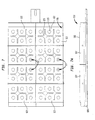
- the laning structure 35 has a first side 46 and a second side 47 and includes a series of finger members 36.
- the finger members 36 extend in a downstream direction 11 from the inlet end 34 of the laning structure to a downstream end 38 of the laning structure 35.
- the finger members 36 define lanes 40 which are spaced from each other in a lateral direction 43 transverse to the downstream direction 11. The lanes arrange the tablets into rows 42.
- the dimensions of the guide wall structure depends upon the size of the tablet or other dosage form.
- the embodiment shown in Figs. 1-9 is designed to handle tablets having a 0.635 cm (1/4" diameter), but the dimensions provided below may be varied for tablets having a 1.74625 cm, 1.27 cm or 1.5875 cm (11/16", 1/2", or 5/8") diameter, or other sizes and types of dosage forms.
- the thickness of the tablets range from about 0.254 cm to 0.8128 cm (0.100" to 0.320").
- the dimensions of the guide wall structure 14 vary with the size of the dosage form handled in the system, the channel 20 in the embodiment of Figs.
- the curved portion 45 has the same width as the channel 20 and is defined by the guide wall structure 14.
- the transition portion 33 in the embodiment of Fig. 4 has a width of 37.7825 cm (14-7/8"). The width of the transitional portion is the dimension transverse to the downstream direction 11.
- the lanes 40 depicted in Fig. 4 extend in the downstream direction 11 and are spaced apart from one another in the lateral direction 43.
- the finger members 36 of the laning structure 35 preferably comprise vibrating guide members 36 which assist in moving the tablets downstream.
- the lanes for the 0.635 cm (1/4") tablets are 1.5875 cm (5/8") wide and 30.7975 cm (12-1/8") long.
- the vibrating members are attached to a selectively operable actuator or actuators 78 such as a solenoid, electric motor operated actuator, hydraulic cylinder or, most preferably, an air cylinder for vibrating the guide members 36.
- the vibrating members agitate the tablets so that they move downstream within the lanes to the downstream end 38.
- the vibrating members which define the lanes are preferably formed with an aperture separating two side bars, so that each bar can be replaced in the event that they become warped or otherwise damaged.
- a dump gate 80 is positioned at the downstream end 38 of the laning structure 35. Adjacent the downstream end .38 is a tablet pickup area 82 of the lanes 40. Adjacent the dump gate on a side of the dump gate opposite the pickup area 82, is a discard ramp 81. In the closed position illustrated in Fig. 4, the dump gate blocks the downstream end 38 of each lane 40.
- the downstream motion of the conveyor belt beneath the laning structure carries tablets downstream until the leading or most downstream tablet in each lane stops against the closed dump gate.
- the laning structure includes a surface beneath the lanes which is sloped in the downstream direction 11 to encourage tablets and other debris to move toward the downstream end 38 of the laning structure 35.
- a form handling device 83 is disposed above the pickup area 82 of the lanes 40.
- the form handling device 83 comprises a robotic handler including an array of finger-like channels 64, a soft rubber suction cup 65 on each such finger 64, and a vacuum pump connected to the finger-like channels 64 for applying suction through the suction cups so that the suction cups can receive and lift the tablets 15.
- the robotic handler 83 receives the tablets and transports them to the packaging machine, where the tablets are released by releasing the vacuum.
- other "pick and place" form handlers are used to transport tablets from pickup area 82 to the packaging machine.
- the array of finger-like channels 64 preferably comprises a two-dimensional array of the channels 64, arranged in a carriage assembly connected to an arm 66 rotatable around a vertical axis.
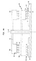
- a suction cup 65 of each channel 64 corresponds to a tablet arranged in the pickup area 82 of the lanes, as depicted in Fig. 4A.
- the arm 66 of the robotic hander After lifting the tablets, the arm 66 of the robotic hander carries the tablets to the packaging machine.
- the dump gate is attached to a selectively operable actuator 79 such as a solenoid, electric motor operated actuator, hydraulic cylinder or, most preferably, an air cylinder for opening and closing the dump gate.
- a selectively operable actuator 79 such as a solenoid, electric motor operated actuator, hydraulic cylinder or, most preferably, an air cylinder for opening and closing the dump gate.
- a number of air cylinder models may be used and the type of air cylinder depends upon the size tablet being packaged.
- the actuator is linked to a control device such as a mechanical, fluidic, electronic or electromechanical controller of known type which is also linked to the robotic handler.
- the controller is a programmable, computer actuated controller having functions controlled by software.
- a detection system with three (3) sensors spaced along the infeed structure 22 is provided for detecting a backup of tablets in the guide wall structure 14.
- the first sensor 51 is located adjacent the exit 27 of the guide portion proximate to the curved portion 45, as depicted in Fig. 2.
- the first sensor 51 provides an indication that the curved portion 45 is clear and to turn on the tablet press 12 and commence flow of tablets through the packaging system.
- the second sensor 52 produces an indication that the tablets have backed up from the exit 27 to the second sensor 52 and that the tablet press rate should be reduced.
- the third sensor 53 located at the entry 26 of the guide portion 25, produces an indication that the tablets backed up to the third sensor 53 and to turn off the tablet press.
- Software and computer hardware may be provided to receive the indications from the sensors and to control the operation of the tablet press.
- preferred embodiments include a guide wall structure 14 having vacuum holes 50 for dedusting the channel 20.
- a vacuum is preferably attached to the top wall 17 of the guide wall structure 14 for this purpose.
- the guide wall structure 14 is preferably formed from a plastic material which is also preferably transparent for visual observation of the tablets transported within the system.
- tablets are carried in the downstream direction 11 on the upper run 10 of the conveyor belt, through the guide wall structure 14.
- the tablets are guided through the curved portion 45 to the plenum structure 32 and travel through the transitional portion 33.
- the tablets In the transitional portion 33, the tablets generally travel from the first side 46 in the lateral direction 43 toward the second side 47 of the laning structure 35 before entering the lanes 40.
- the tablets Upon entering the lanes, the tablets travel in the downstream direction 11.
- a row 42 of tablets stack up in upstream-to-downstream order within the tablet pickup area 82 of each lane 40.
- the form handling device 83 engages the tablets 15 stacked within the various lanes 40 and lifts a predetermined number of tablets out of each lane during each cycle of operation.
- the operation of the embodiment having the robotic tablet handler will now be described. As depicted in Fig. 4A, the robotic tablet handler descends from a first position 83A to a second position 83b to receive the tablets within the lanes 40. For ease of illustration, only a few of the lanes 40 depicted in Fig. 4 are depicted in Fig. 4A.
- the vacuum is applied and the tablets are received within the suction cups 65.
- the arm 66 raises the array of finger-like channels 64 and suction cups 65 to position 83a and rotates 180° to position 83C, over the packaging machine 90.
- the tablet 15b immediately after the last tablet 15a lifted by the robotic handler 83 then becomes the leading tablet of the next group to be received be the robotic tablet hander 83.
- the controller operates the actuator in synchronism with the handler 83 or other form handling device so that the dump gate 80 opens after the handler 83 has engaged a group of tablets and remains open for a preselected open time after the handler 83 has lifted that group of tablets out of the laning structure 35. While the dump gate is open, debris accumulated in each lane moves downstream, past the dump gate 80 and down the discard ramp 81, where debris is collected for disposal. The next group of tablets move downstream to the downstream end 38.
- the open time of the dump gate 80 is selected so that it is just slightly less than the time required for the leading tablet of the next group to reach the downstream end 38 of the lane 40. Thus, the dump gate 80 returns to the closed position just before the leading tablet (for example, tablet 15b) of the next group arrives at the dump gate 80. This cycle of operations is repeated.
- the dump date may be manually operated in some embodiments, which is less preferred. Attempts have been made heretofore to use a dump gate which is manually actuated by an operator in response to visible accumulation of debris in the lanes, or which is actuated at some lengthy intervals. Where the dump gate is manually operated, debris such as tablets or parts of tablets missed by the robotic tablet handler interfere with the next set of tablets preceding to the pickup area 82 through the lanes 40. Breakage of tablets occurs in the laning area before a human operator is alerted who can operate the dump gate. Also, when the manually operated dump gate is held open, some good tablets pass out of the dump gate and are wasted. By contrast, in the preferred systems according to this aspect of the invention, debris is cleared during each cycle of the handler, without wasting good tablets.
- inventions include an infeed structure, a plenum structure and a laning structure adapted to different sized tablets and different types of dosage forms.
- Certain preferred embodiments also include a member 60, preferably having a triangular shape, at the juncture of the guide portion 25 and the plenum structure 32.
- the triangle 60 alleviates jamming of the tablets at this juncture. It has been found that this triangular member 60 is not required for 0.635 cm (1/4") tablets in the embodiment of Figs. 1-9, but is preferred for larger tablets. For example, in packaging 1.27 cm (1/2") tablets, a stationary triangular member is preferably used to alleviate jamming.
- a triangular member which is spring-loaded is preferably used.
- the triangular member depicted in Figs. 10 and 11, has a first leg 61 and a second leg 62 facing upstream and a third leg 63 facing downstream, facing the laning structure 35.
- the spring-loaded triangular member 60 is moveable from side to side in traverse directions 71 and 72 shown in Fig. 11, transverse to the downstream direction 11.
- the triangle is biased in a central position 70 by a biasing means 73, including a spring or other conventional biasing devices.
- the tablets bounce off the triangle, which alleviates jamming of the tablets in the plenum entry 28.
- Tablets entering the plenum entry may slide along the first leg 61 and second leg 62 and proceed to the transitional portion 33. However, in the event that tablets 15 begin to jam up, the tablets apply a small force upon the triangular member, which compresses the biasing device or spring 73. As shown in Fig. 11, the triangle may be moved to one side or the other to offset positions 70a or 70b. The spring reacts, relieving the force of the tablets. The compressibility of the spring must be such that the tablets are not broken.
- the packaging device 90 includes a sealing machine 91 for forming packaged dosage forms.
- the packages are comprised of first and second sheets of packaging material, preferably foil laminate, which are sealed together in the sealing machine.
- An example of this type of packaging machine is a Clockner blister-forming machine. Model No. CP11.4 may be used.
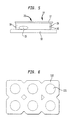
- Blisters 111 which are essentially cup-shaped depressions in the packaging material, have been provided in at least one of the sheets for holding the tablets. In the finished package, which is depicted in Fig. 6, each tablet occupies a pocket formed by the blisters 111.
- blister packages of the type described concerning certain embodiments of copending, commonly assigned United States patent application Serial No. 09/053,298, filed April 1, 1998, hereby incorporated by reference herein, may be used.
- the packaging device 90 is generally of the type known as a "form, fill and seal" machine.
- the machine forms a web of a packaging material into blisters, whereupon the form handler 83 places the tablets in the blisters.
- each suction cup 65 of the robotic handler corresponds to a blister 111 in the packaging material, as depicted in Fig. 4A.
- the robotic handler received tablets at the pickup area 82 and rotates 180° from position 83C to position 83D, toward the packaging material 112 on support 114. After the arm 66 lowers to the packaging material, the tablets are release into blisters 111.
- the packaging material advances along a conveyor belt, series of rollers or a similar conveyance device 68 to a sealing machine through a series of checking systems which ensure that the first sheet is free from displaced tablets and debris prior to reaching the sealing machine.
- the packaging material is sealed to a web or sheet of lid stock so that the lid stock closes the blisters and holds the tablets in the blisters.
- the sealing machine includes a top and bottom plate.
- the top and bottom plates of the sealing machine each have sealing faces, for engaging the lid stock and packaging material, respectively.
- blister cavities 115 are provided in the sealing face 116 of the bottom plate 113.
- the top plate may include blister cavities, as well.
- the plates preferably have registration markers 17 so that the top and bottom plates can be properly aligned. At least one of the plates, typically the top plate, is heated so that a heat-activated material in the packaging material or lid stock seals the tablet package when the top and bottom plates are brought into engagement. Most preferably, the bottom plate is also heated.
- the heaters are connected to controllers for controlling the heating of the plates in the conventional manner.
- the web of the packaging material is transferred from support 114 to the sealing face 116 of the bottom plate 113 so that the blisters 111 rest in the blister cavities 115 of the bottom plate 113.
- the lid stock is placed on the packaging material, overlying the tablets in the blisters and the sealing machine urges the top plate and bottom plate together, so that these plates engage the package material and lid stock therebetween.
- the top and bottom plates are brought together to seal the packaging material.
- sealing occurs according to three (3) parameters: heat, pressure and time.
- At least the bottom plate is designed with recessed regions 120 depicted in Fig. 7.
- the recessed regions apply no pressure to the blister pack material and the sealing face 116 comprises relatively raised regions where the seal is to be formed. This feature focuses the force and heat of the sealing device on the portions of the blister pack where sealing is desired.
- the plates are disengaged and the sealed blister pack 110 is transported to a blister pack card punch and thereafter to a cartoner for arrangement in boxes.
- Fig. 6 depicts a blister package for 1.27 cm (1/2") tablets.
- At least one of the top and bottom plates is designed to evenly distribute the force and heat of the sealing machine along the sealing faces of the plates.
- the present invention addresses this problem by providing, rather than one continuous bottom plate 113, a plate comprised of a plurality of blocks 122 which can move with respect to one another over a range of motion.
- a plate comprised of a plurality of blocks 122 which can move with respect to one another over a range of motion.
- four movable blocks 122 are provided.
- Each block 122 depicted in Fig. 9, has a rear face 123 opposite the sealing face 116 and a circular depression 125 in the rear face.
- Each block also has a compartment cut out for heaters which communicate with controls for heating the plate, as discussed above.
- the blocks 122 are formed from metals such as steel, aluminum or the like which are selected according to conventional criteria such as wear resistance and good heat transfer.
- Each block 122 rests on a ball-like member 126, depicted in Fig. 8, which is attached to a base 128 so that the ball 126 is engaged by the circular depression 125 and each block 122 is floatably supported by the base 128.
- the spacing of the blocks 122 on the base accommodates individual tilting of each block with respect to the horizontal plane.
- each block 122 is free to tilt around any horizontal axis. This design has the benefit of achieving better sealing in the tablet packages.
- the various blocks constituting the bottom plate 122 tilt and adjust to achieve an evenly distributed pressure over the blister pack material. After a predetermined sealing time, the plates are released from the package 110, which proceeds to the cartoner.
- each block can be mounted to the base by a pad of a resilient material such as a high-temperature silicone rubber, or by a set of springs, so that each block is free to move relative to the base in a limited range of tilting movement.
- a dual-gimbal mount wherein each block is pivotally mounted to a gimbal frame for tilting movement around a first horizontal axis, and the gimbal frame is pivotally mounted to the base for tilting movement around a second horizontal axis perpendicular to the first horizontal axis.
- each block can be mounted to the base by a pad of a resilient material such as a high-temperature silicone rubber, or by a set of springs, so that each block is free to move relative to the base in a limited range of tilting movement.
- the bottom plate has individual blocks, whereas the top plate is a unitary, solid part.
- the reverse arrangement with a solid bottom plate and a top plate composed of movable parts, can also be employed.
- both plates can be formed with movable parts.
- the present invention can be applied in the packaging of pharmaceuticals.
Landscapes
- Engineering & Computer Science (AREA)
- Mechanical Engineering (AREA)
- Basic Packing Technique (AREA)
- Medical Preparation Storing Or Oral Administration Devices (AREA)
- Package Closures (AREA)
- Framework For Endless Conveyors (AREA)
- Attitude Control For Articles On Conveyors (AREA)
- Closing Of Containers (AREA)
- Control And Other Processes For Unpacking Of Materials (AREA)
Abstract
Description
Claims (9)
- An assembly for handling and packaging pharmaceutical dosage forms (15), including:(a) an infeed structure (22) for accepting a series of dosage forms (15) including a surface (10) movable in a downstream direction (11), a laning structure (35) defining a plurality of lanes (40) extending in said downstream direction (11) and having a downstream end (38), and a plenum structure (32) extending from said infeed structure (22) to said laning structure (35) including a guide portion (25) for guiding dosage (15) forms carried by said surface (10) into said laning structure (35);(b) a form handling device (83) for receiving dosage forms (15) and transporting dosage forms (15) from said laning structure (35) to a packaging device (90);(c) a dump gate (80) having a closed position wherein said dump gate (80) blocks said lanes (40) at said downstream ends thereof, whereby dosage forms (15) will accumulate in said lanes (40) when said dump gate (80) is in said closed position and an open position in which said dump gate (80) does not block the lanes (40),
characterised by:(d) a timed controller for opening said dump gate (80) after said handling device (83) receives dosage forms (15) whereby debris will be carried downstream out of said laning structure (35) after said form handling device (83) receives dosage forms (15) from said laning structure (35). - The assembly of claim 1 wherein said timed controller further comprises a computer communicating with said form handling device (83) and said dump gate (80).
- The assembly of claim 1, further comprising a guide wall structure defining said guide portion (25) and including a curved portion (45).
- The assembly of claim 3 wherein said guide wall structure also defines said plenum structure (32), said plenum structure (32) including a plenum entry (28) and said guide wall structure (14) being shaped to guide dosage forms (15) so that dosage forms (15) enter said plenum structure (32) at said plenum entry adjacent a first side (46) of said laning structure (35) and travel in a lateral direction (43) transverse to said downstream direction (11) toward a second side (47) of said laning structure (35) before entering said lanes (40).
- The assembly of claim 3 wherein said curved portion (45) includes a member adjacent said plenum entry (28) for relieving jamming of dosage forms (15).
- The assembly of claim 5, wherein said member comprises a movable member and further comprising a biasing means for vibrating said movable member to agitate dosage forms (15).
- The assembly of claim 1 wherein said laning structure (35) includes a surface for supporting dosage forms (15), said surface sloping in said downstream direction (11) to said dump gate (80) so that debris is carried out of said laning structure (35) by said surface when the dump gate (80) is in the open position.
- The assembly of claim 4 wherein said packaging device (90) includes a top plate and a bottom plate (113) for engaging a packaging material and a lid stock therebetween to seal the packaging material and lid stock together, forming packaged dosage forms (15).
- The assembly of claim 8 wherein at least one of said top plate and said bottom plate (113) includes a plurality of blocks (122) and a base (128) for supporting said plurality of blocks, said blocks being floatably supported on the base and individually movable with respect to the base (128).
Priority Applications (1)
| Application Number | Priority Date | Filing Date | Title |
|---|---|---|---|
| EP04025128A EP1591360B1 (en) | 1998-03-09 | 1999-03-09 | Apparatus for handling and packaging friable tablets |
Applications Claiming Priority (3)
| Application Number | Priority Date | Filing Date | Title |
|---|---|---|---|
| US7736398P | 1998-03-09 | 1998-03-09 | |
| US77363P | 1998-03-09 | ||
| PCT/US1999/005103 WO1999046168A1 (en) | 1998-03-09 | 1999-03-09 | Apparatus for handling and packaging friable tablets |
Related Child Applications (1)
| Application Number | Title | Priority Date | Filing Date |
|---|---|---|---|
| EP04025128A Division EP1591360B1 (en) | 1998-03-09 | 1999-03-09 | Apparatus for handling and packaging friable tablets |
Publications (3)
| Publication Number | Publication Date |
|---|---|
| EP1107911A1 EP1107911A1 (en) | 2001-06-20 |
| EP1107911A4 EP1107911A4 (en) | 2003-05-02 |
| EP1107911B1 true EP1107911B1 (en) | 2005-01-19 |
Family
ID=22137621
Family Applications (1)
| Application Number | Title | Priority Date | Filing Date |
|---|---|---|---|
| EP99914893A Expired - Lifetime EP1107911B1 (en) | 1998-03-09 | 1999-03-09 | Apparatus for handling and packaging friable tablets |
Country Status (11)
| Country | Link |
|---|---|
| US (2) | US6269615B1 (en) |
| EP (1) | EP1107911B1 (en) |
| JP (1) | JP4237405B2 (en) |
| AT (2) | ATE287358T1 (en) |
| AU (1) | AU734383B2 (en) |
| CY (1) | CY1107443T1 (en) |
| DE (2) | DE69936949T2 (en) |
| DK (1) | DK1591360T3 (en) |
| ES (2) | ES2293145T3 (en) |
| PT (1) | PT1591360E (en) |
| WO (1) | WO1999046168A1 (en) |
Families Citing this family (41)
| Publication number | Priority date | Publication date | Assignee | Title |
|---|---|---|---|---|
| US8071128B2 (en) * | 1996-06-14 | 2011-12-06 | Kyowa Hakko Kirin Co., Ltd. | Intrabuccally rapidly disintegrating tablet and a production method of the tablets |
| WO2001028856A1 (en) * | 1999-10-15 | 2001-04-26 | Hartness International, Inc. | Continuous circular motion case packing and depacking apparatus and method |
| US9358214B2 (en) | 2001-10-04 | 2016-06-07 | Adare Pharmaceuticals, Inc. | Timed, sustained release systems for propranolol |
| US8321036B2 (en) * | 2002-02-15 | 2012-11-27 | Data Sciences International, Inc. | Cardiac rhythm management device |
| AU2003298776A1 (en) * | 2002-11-25 | 2004-06-18 | Purdue Research Foundation | Mannose-based fast dissolving tablets |
| US8367111B2 (en) | 2002-12-31 | 2013-02-05 | Aptalis Pharmatech, Inc. | Extended release dosage forms of propranolol hydrochloride |
| CN1819819B (en) * | 2003-05-07 | 2011-03-09 | 株式会社三养社 | Highly plastic granules for the preparation of fast-melting tablets |
| US7114535B2 (en) * | 2003-08-28 | 2006-10-03 | Hartness International, Inc. | Circular motion filling machine and method |
| DE10352885A1 (en) * | 2003-11-10 | 2005-07-07 | Khs Maschinen- Und Anlagenbau Ag | Device for feeding and removing containers |
| US7278531B2 (en) | 2004-06-29 | 2007-10-09 | Hartness International, Inc. | Flexible conveyor and connection elements |
| US8545881B2 (en) | 2004-04-19 | 2013-10-01 | Eurand Pharmaceuticals, Ltd. | Orally disintegrating tablets and methods of manufacture |
| US7299832B2 (en) | 2004-06-29 | 2007-11-27 | Hartness International, Inc. | Rotary filling machine and related components, and related method |
| US7331156B2 (en) | 2004-06-29 | 2008-02-19 | Hartness International, Inc. | System for securely conveying articles and related components |
| US8747895B2 (en) | 2004-09-13 | 2014-06-10 | Aptalis Pharmatech, Inc. | Orally disintegrating tablets of atomoxetine |
| DE102004049560B4 (en) * | 2004-10-12 | 2006-08-31 | Mediseal Gmbh | Method and device for placing tablets in the courtyards of a deep-drawn bottom sheet |
| US9884014B2 (en) | 2004-10-12 | 2018-02-06 | Adare Pharmaceuticals, Inc. | Taste-masked pharmaceutical compositions |
| AU2005299490C1 (en) | 2004-10-21 | 2012-01-19 | Adare Pharmaceuticals, Inc. | Taste-masked pharmaceutical compositions with gastrosoluble pore-formers |
| US20060105038A1 (en) * | 2004-11-12 | 2006-05-18 | Eurand Pharmaceuticals Limited | Taste-masked pharmaceutical compositions prepared by coacervation |
| DE102005007532B3 (en) * | 2005-02-17 | 2006-08-10 | Uhlmann Pac-Systeme Gmbh & Co. Kg | Transfer device for sorting products like tablets, chocolate drops and capsules in containers on a card transfers these products into cups in a continuously moving foil strip |
| US9161918B2 (en) | 2005-05-02 | 2015-10-20 | Adare Pharmaceuticals, Inc. | Timed, pulsatile release systems |
| DE102005032177B3 (en) * | 2005-07-09 | 2006-06-01 | Uhlmann Pac-Systeme Gmbh & Co. Kg. | Machine sealing sheet with indentations using cover sheet e.g. for blister packaging of products, includes roller with zones of reduced circumferential friction |
| DE102005049883B4 (en) * | 2005-10-17 | 2008-03-27 | Uhlmann Pac-Systeme Gmbh & Co Kg | Device for transferring stored in a reservoir bulk material |
| AT504327B8 (en) * | 2006-09-08 | 2008-09-15 | Knapp Logistik Automation | TABLETS FILLER |
| EP3323405B1 (en) * | 2006-09-11 | 2024-12-04 | Synergie Medicale BRG INC. | Medication dispenser system and method |
| US7386970B2 (en) * | 2006-11-03 | 2008-06-17 | Dade Behring Inc. | Method for dispensing tablets into a multi-compartment clinical reagent container |
| ITBO20070178A1 (en) * | 2007-03-14 | 2008-09-15 | Marchesini Group Spa | DEVICE FOR THE COLLECTION OF ITEMS FROM A POWER STATION AND TO STORE THEMSELVES IN CORRESPONDING ALVEOLI OF A HOLLOWED TAPE |
| KR101765357B1 (en) | 2009-12-02 | 2017-08-04 | 아데어 파마수티컬스 에스.알.엘. | Fexofenadine microcapsules and compositions containing them |
| AR079862A1 (en) * | 2010-01-08 | 2012-02-22 | Eurand Inc | COMPOSITION OF TOPIRAMATO WITH MASKED FLAVOR, A DISPOSABLE ORALLY COMPRESSED UNDERSTANDING THE SAME AND PREPARATION METHOD |
| IT1400272B1 (en) * | 2010-06-04 | 2013-05-24 | Ima Safe S R L Unipersonale | PADS DISTRIBUTION MACHINE AND ITS PROCEDURE |
| MX365568B (en) | 2010-12-02 | 2019-06-07 | Adare Pharmaceuticals Inc | Rapidly dispersing granules, orally disintegrating tablets and methods. |
| CA3018828C (en) | 2014-09-17 | 2021-05-11 | Steerlife India Private Limited | Effervescent composition and method of making it |
| CA2939591C (en) * | 2015-08-25 | 2021-11-09 | Chudy Group, LLC | Plural-mode automatic medicament packaging system |
| JP6133388B2 (en) * | 2015-11-25 | 2017-05-24 | キヤノンマーケティングジャパン株式会社 | Tablet feeder |
| WO2017098481A1 (en) | 2015-12-12 | 2017-06-15 | Steerlife India Private Limited | Effervescent compositions of metformin and processes for preparation thereof |
| SG10202107367SA (en) | 2016-12-31 | 2021-08-30 | Bioxcel Therapeutics Inc | Use of sublingual dexmedetomidine for the treatment of agitation |
| DE202017102645U1 (en) | 2017-05-03 | 2018-08-06 | Romaco Kilian Gmbh | Drainage device for compacts of a rotary tablet press and rotary tablet press with drain device |
| KR102026982B1 (en) * | 2018-02-02 | 2019-09-30 | 주식회사 씨티씨바이오 | Capsule filling apparatus |
| ES3004544T3 (en) | 2018-06-27 | 2025-03-12 | Bioxcel Therapeutics Inc | Film formulations containing dexmedetomidine and methods of producing them |
| US20240024288A1 (en) | 2019-07-19 | 2024-01-25 | Bioxcel Therapeutics, Inc. | Non-sedating dexmedetomidine treatment regimens |
| DE102021210750B3 (en) * | 2021-09-27 | 2022-08-04 | OPTIMA pharma GmbH | Method and device for rectifying faults in a filling and/or sealing and/or post-processing plant |
| US11806334B1 (en) | 2023-01-12 | 2023-11-07 | Bioxcel Therapeutics, Inc. | Non-sedating dexmedetomidine treatment regimens |
Family Cites Families (17)
| Publication number | Priority date | Publication date | Assignee | Title |
|---|---|---|---|---|
| US2735599A (en) * | 1956-02-21 | Bottle case | ||
| US2544125A (en) * | 1944-12-26 | 1951-03-06 | Joseph C Bain | Packaging machine having article receiving and transferring sections for handling articles in group formation |
| US3142947A (en) * | 1961-10-09 | 1964-08-04 | Joseph H Walter | Bottle packing machine |
| US3316688A (en) * | 1964-01-16 | 1967-05-02 | Otto C Niederer | Packing equipment |
| US3327450A (en) * | 1964-08-12 | 1967-06-27 | Terry L Carter | Case packer |
| US3340672A (en) * | 1965-01-28 | 1967-09-12 | Emhart Corp | Case packing machine for tiered articles |
| US3465495A (en) * | 1965-08-16 | 1969-09-09 | Sunkist Growers Inc | Apparatus for boxing layers of articles such as fruit and the like |
| US3490197A (en) * | 1968-04-15 | 1970-01-20 | American Home Prod | Tablet counting and bottling machine |
| US3609938A (en) * | 1968-12-18 | 1971-10-05 | Sunkist Growers Inc | Device to pack articles in boxes |
| US3722173A (en) * | 1971-12-07 | 1973-03-27 | H Noguchi | Alignment and packaging unit for eggs |
| US4435941A (en) * | 1979-01-25 | 1984-03-13 | Booth Manufacturing Company | Packaging machine |
| IT1169585B (en) * | 1983-10-18 | 1987-06-03 | Illycaffe Spa | MACHINE TO PRODUCE A CONTINUOUS TAPE BEARING COFFEE PODS FOR AN AUTOMATIC ESPRESSO COFFEE MACHINE |
| US5123227A (en) * | 1988-04-21 | 1992-06-23 | Snow Brand Milk Products Co., Ltd. | Positioning and press-sealing means |
| SE461145B (en) * | 1988-05-19 | 1990-01-15 | Plm Ab | SEAT AND DEVICE CONSIDER THE CONTAINER OF THE CONTAINER |
| US5178878A (en) | 1989-10-02 | 1993-01-12 | Cima Labs, Inc. | Effervescent dosage form with microparticles |
| US5223264A (en) | 1989-10-02 | 1993-06-29 | Cima Labs, Inc. | Pediatric effervescent dosage form |
| DE4406089C2 (en) * | 1994-02-24 | 1996-04-11 | Lingenfelder Oli Spezialanlage | Device for filling tablets or the like into tablet tubes |
-
1999
- 1999-03-09 EP EP99914893A patent/EP1107911B1/en not_active Expired - Lifetime
- 1999-03-09 JP JP2000535554A patent/JP4237405B2/en not_active Expired - Lifetime
- 1999-03-09 DE DE69936949T patent/DE69936949T2/en not_active Expired - Lifetime
- 1999-03-09 US US09/264,994 patent/US6269615B1/en not_active Expired - Lifetime
- 1999-03-09 AU AU33538/99A patent/AU734383B2/en not_active Expired
- 1999-03-09 AT AT99914893T patent/ATE287358T1/en active
- 1999-03-09 DK DK04025128T patent/DK1591360T3/en active
- 1999-03-09 WO PCT/US1999/005103 patent/WO1999046168A1/en not_active Ceased
- 1999-03-09 DE DE69923326T patent/DE69923326T2/en not_active Expired - Lifetime
- 1999-03-09 ES ES04025128T patent/ES2293145T3/en not_active Expired - Lifetime
- 1999-03-09 ES ES99914893T patent/ES2237912T3/en not_active Expired - Lifetime
- 1999-03-09 AT AT04025128T patent/ATE370889T1/en active
- 1999-03-09 PT PT04025128T patent/PT1591360E/en unknown
-
2001
- 2001-05-02 US US09/847,675 patent/US6311462B2/en not_active Expired - Lifetime
-
2007
- 2007-11-14 CY CY20071101475T patent/CY1107443T1/en unknown
Also Published As
| Publication number | Publication date |
|---|---|
| DE69936949D1 (en) | 2007-10-04 |
| ES2293145T3 (en) | 2008-03-16 |
| JP4237405B2 (en) | 2009-03-11 |
| EP1107911A4 (en) | 2003-05-02 |
| AU734383B2 (en) | 2001-06-14 |
| DK1591360T3 (en) | 2007-12-27 |
| CY1107443T1 (en) | 2012-12-19 |
| PT1591360E (en) | 2007-10-09 |
| US6311462B2 (en) | 2001-11-06 |
| ATE287358T1 (en) | 2005-02-15 |
| JP2002505982A (en) | 2002-02-26 |
| US20010017025A1 (en) | 2001-08-30 |
| ATE370889T1 (en) | 2007-09-15 |
| DE69936949T2 (en) | 2008-05-15 |
| WO1999046168A1 (en) | 1999-09-16 |
| DE69923326T2 (en) | 2006-01-05 |
| DE69923326D1 (en) | 2005-02-24 |
| US6269615B1 (en) | 2001-08-07 |
| EP1107911A1 (en) | 2001-06-20 |
| AU3353899A (en) | 1999-09-27 |
| ES2237912T3 (en) | 2005-08-01 |
Similar Documents
| Publication | Publication Date | Title |
|---|---|---|
| AU734383B2 (en) | Apparatus for handling and packaging friable tablets | |
| US5607282A (en) | Depalletizing and dispensing apparatus and method | |
| EP1986941B1 (en) | Pick and place handling device and method for its use | |
| CA1226237A (en) | Materials handling apparatus | |
| US5737902A (en) | Apparatus and method for packaging pills | |
| US6398008B1 (en) | Aligning and conveying method of packaged article and apparatus thereof | |
| US5765337A (en) | Apparatus and method for stacking and boxing stackable articles | |
| US20020194815A1 (en) | Apparatus for handling and packaging friable tablets | |
| JP2530208Y2 (en) | Equipment for filling sheet blanks into containers | |
| US5613346A (en) | Apparatus for removing packing material from packed article | |
| EP1591360B1 (en) | Apparatus for handling and packaging friable tablets | |
| JPH11513648A (en) | Can lid supply device | |
| JP2001002033A (en) | Distributing device for continuous item packaging bags | |
| GB2435252A (en) | Improved pick and place handling device | |
| JPH0672814U (en) | Unpacking machine | |
| KR101974969B1 (en) | a robot bag placer and a control method of the same | |
| KR200144135Y1 (en) | Bag feeder of juice packing machine | |
| GB2378933A (en) | Article handling apparatus | |
| JPH03147197A (en) | Commodity conveying device for automatic vending machine | |
| JPH0516604U (en) | Roll product boxing machine | |
| GB2266046A (en) | Article orientator |
Legal Events
| Date | Code | Title | Description |
|---|---|---|---|
| PUAI | Public reference made under article 153(3) epc to a published international application that has entered the european phase |
Free format text: ORIGINAL CODE: 0009012 |
|
| 17P | Request for examination filed |
Effective date: 20000809 |
|
| AK | Designated contracting states |
Kind code of ref document: A1 Designated state(s): AT BE CH CY DE DK ES FI FR GB GR IE IT LI LU MC NL PT SE |
|
| A4 | Supplementary search report drawn up and despatched |
Effective date: 20030319 |
|
| RIC1 | Information provided on ipc code assigned before grant |
Ipc: 7B 65B 5/10 B Ipc: 7B 65B 51/14 B Ipc: 7B 65B 35/30 B Ipc: 7B 65B 23/00 B Ipc: 7B 65B 7/28 A |
|
| 17Q | First examination report despatched |
Effective date: 20030908 |
|
| GRAP | Despatch of communication of intention to grant a patent |
Free format text: ORIGINAL CODE: EPIDOSNIGR1 |
|
| GRAS | Grant fee paid |
Free format text: ORIGINAL CODE: EPIDOSNIGR3 |
|
| GRAA | (expected) grant |
Free format text: ORIGINAL CODE: 0009210 |
|
| AK | Designated contracting states |
Kind code of ref document: B1 Designated state(s): AT BE CH CY DE DK ES FI FR GB GR IE IT LI LU MC NL PT SE |
|
| PG25 | Lapsed in a contracting state [announced via postgrant information from national office to epo] |
Ref country code: NL Free format text: LAPSE BECAUSE OF FAILURE TO SUBMIT A TRANSLATION OF THE DESCRIPTION OR TO PAY THE FEE WITHIN THE PRESCRIBED TIME-LIMIT Effective date: 20050119 Ref country code: FI Free format text: LAPSE BECAUSE OF FAILURE TO SUBMIT A TRANSLATION OF THE DESCRIPTION OR TO PAY THE FEE WITHIN THE PRESCRIBED TIME-LIMIT Effective date: 20050119 |
|
| REG | Reference to a national code |
Ref country code: GB Ref legal event code: FG4D |
|
| REG | Reference to a national code |
Ref country code: CH Ref legal event code: EP |
|
| REG | Reference to a national code |
Ref country code: IE Ref legal event code: FG4D |
|
| REF | Corresponds to: |
Ref document number: 69923326 Country of ref document: DE Date of ref document: 20050224 Kind code of ref document: P |
|
| PG25 | Lapsed in a contracting state [announced via postgrant information from national office to epo] |
Ref country code: LU Free format text: LAPSE BECAUSE OF NON-PAYMENT OF DUE FEES Effective date: 20050309 Ref country code: IE Free format text: LAPSE BECAUSE OF NON-PAYMENT OF DUE FEES Effective date: 20050309 Ref country code: CY Free format text: LAPSE BECAUSE OF FAILURE TO SUBMIT A TRANSLATION OF THE DESCRIPTION OR TO PAY THE FEE WITHIN THE PRESCRIBED TIME-LIMIT Effective date: 20050309 |
|
| PG25 | Lapsed in a contracting state [announced via postgrant information from national office to epo] |
Ref country code: MC Free format text: LAPSE BECAUSE OF NON-PAYMENT OF DUE FEES Effective date: 20050331 |
|
| PG25 | Lapsed in a contracting state [announced via postgrant information from national office to epo] |
Ref country code: GR Free format text: LAPSE BECAUSE OF FAILURE TO SUBMIT A TRANSLATION OF THE DESCRIPTION OR TO PAY THE FEE WITHIN THE PRESCRIBED TIME-LIMIT Effective date: 20050419 Ref country code: DK Free format text: LAPSE BECAUSE OF FAILURE TO SUBMIT A TRANSLATION OF THE DESCRIPTION OR TO PAY THE FEE WITHIN THE PRESCRIBED TIME-LIMIT Effective date: 20050419 |
|
| REG | Reference to a national code |
Ref country code: SE Ref legal event code: TRGR |
|
| NLV1 | Nl: lapsed or annulled due to failure to fulfill the requirements of art. 29p and 29m of the patents act | ||
| REG | Reference to a national code |
Ref country code: CH Ref legal event code: NV Representative=s name: ARNOLD & SIEDSMA AG |
|
| REG | Reference to a national code |
Ref country code: ES Ref legal event code: FG2A Ref document number: 2237912 Country of ref document: ES Kind code of ref document: T3 |
|
| PLBE | No opposition filed within time limit |
Free format text: ORIGINAL CODE: 0009261 |
|
| STAA | Information on the status of an ep patent application or granted ep patent |
Free format text: STATUS: NO OPPOSITION FILED WITHIN TIME LIMIT |
|
| REG | Reference to a national code |
Ref country code: IE Ref legal event code: MM4A |
|
| ET | Fr: translation filed | ||
| 26N | No opposition filed |
Effective date: 20051020 |
|
| PG25 | Lapsed in a contracting state [announced via postgrant information from national office to epo] |
Ref country code: PT Free format text: LAPSE BECAUSE OF NON-PAYMENT OF DUE FEES Effective date: 20050619 |
|
| REG | Reference to a national code |
Ref country code: FR Ref legal event code: PLFP Year of fee payment: 18 |
|
| REG | Reference to a national code |
Ref country code: FR Ref legal event code: PLFP Year of fee payment: 19 |
|
| REG | Reference to a national code |
Ref country code: FR Ref legal event code: PLFP Year of fee payment: 20 |
|
| PGFP | Annual fee paid to national office [announced via postgrant information from national office to epo] |
Ref country code: GB Payment date: 20180321 Year of fee payment: 20 Ref country code: CH Payment date: 20180321 Year of fee payment: 20 Ref country code: DE Payment date: 20180322 Year of fee payment: 20 |
|
| PGFP | Annual fee paid to national office [announced via postgrant information from national office to epo] |
Ref country code: AT Payment date: 20180322 Year of fee payment: 20 Ref country code: BE Payment date: 20180321 Year of fee payment: 20 Ref country code: FR Payment date: 20180323 Year of fee payment: 20 Ref country code: SE Payment date: 20180321 Year of fee payment: 20 |
|
| PGFP | Annual fee paid to national office [announced via postgrant information from national office to epo] |
Ref country code: ES Payment date: 20180427 Year of fee payment: 20 |
|
| PGFP | Annual fee paid to national office [announced via postgrant information from national office to epo] |
Ref country code: IT Payment date: 20180327 Year of fee payment: 20 |
|
| REG | Reference to a national code |
Ref country code: DE Ref legal event code: R071 Ref document number: 69923326 Country of ref document: DE |
|
| REG | Reference to a national code |
Ref country code: CH Ref legal event code: PL |
|
| REG | Reference to a national code |
Ref country code: GB Ref legal event code: PE20 Expiry date: 20190308 |
|
| REG | Reference to a national code |
Ref country code: AT Ref legal event code: MK07 Ref document number: 287358 Country of ref document: AT Kind code of ref document: T Effective date: 20190309 |
|
| PG25 | Lapsed in a contracting state [announced via postgrant information from national office to epo] |
Ref country code: GB Free format text: LAPSE BECAUSE OF EXPIRATION OF PROTECTION Effective date: 20190308 |
|
| REG | Reference to a national code |
Ref country code: BE Ref legal event code: MK Effective date: 20190309 |
|
| REG | Reference to a national code |
Ref country code: ES Ref legal event code: FD2A Effective date: 20210205 |
|
| PG25 | Lapsed in a contracting state [announced via postgrant information from national office to epo] |
Ref country code: ES Free format text: LAPSE BECAUSE OF EXPIRATION OF PROTECTION Effective date: 20190310 |