The present invention relates to a method according to the preamble of
Claim 1 for reducing the power consumption of a mobile station, a system
according to the preamble of Claim 13 and a mobile station according to the
preamble of Claim 20.
Data transfer between different data transfer devices can be arranged so
that the data transfer devices, between which information is to be
transferred, are connected for the time needed for data transfer. This so-called
circuit switched connection is maintained until the user stops the data
transfer. In these cases, most of the connection time is used for feeding the
commands given by the user, and only a small part of the time is used for
actual data transfer. This limits, among other things, the maximum number
of simultaneous users of the same application. Another possibility is to use
so-called packet-switched data transfer. This means that information is
transferred between data transfer devices in packet form, whereby the time
between packets is freely available for other data transfer devices. In that
way, the number of simultaneous users can be increased especially in
wireless data transfer networks, such as cellular networks, because then the
mobile stations in the area of the same cell can use the same transmission
channel. A well known cellular communication system is the GSM system,
for which a packet transmission service called GPRS (General Packet Radio
Service) has been developed. The blocks that are of central importance for
the operation of the GPRS system are shown as a block diagram in Figure
1. The Serving GPRS Support Node (SGSN) controls the operation of the
packet switching service on the side of the cellular network. The serving
GPRS support node takes care of the attachment to and detachment from
the network of the mobile station 2, updating the location of the mobile
station 2 and directing the data packets to the right addresses. The mobile
station 2 is connected to the base station subsystem BSS via a radio
interface Um (Fig. 1). The base station system is connected to the serving
GPRS support node SGSN via a BSS-SGSN interface Gb. In the base
station subsystem BSS, the base transceiver station BTS and the base
station controller BSC are interconnected by a BTS-BSC interface called
Abis. The serving GPRS support nodes SGSN can communicate with other
serving GPRS support nodes SGSN by means of the Gateway GPRS
Support Node (GGSN).
The operation of both the mobile station 2 and the serving GPRS support
node SGSN can be divided into several layers, each of which has a different
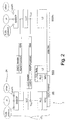
function, as shown in Fig. 2.
The transfer of information, such as control signalling and information sent
by the user, between the mobile station 2 and the serving support node
SGSN preferably takes place in the form of data frames. The data frame of
each layer consists of a header field and a data field. Fig. 2 also shows the
structure of the data frames used in the GPRS system in different layers.
The information contained by the data field can be, for example, information
fed by the user of the mobile station or signalling information. The functional
tasks of the layers of the GPRS system are shown in the following.
Lowest in the Data Link Layer is the MAC (Media Access Control) layer,
which takes care of using the radio path in communications between the
mobile station 2 and the Base Station Subsystem), such as allocating the
channels for transmission and reception of packets.
A time division / frequency division multiple access (TDMA/FDMA) method
according to the GSM system is used in the physical layer (radio path) in the
GPRS system. The basic transmission unit is called a burst, which consists
of a certain number of bits sent to the radio path. The length of a burst is
15/26 ms, or approx. 0,577 ms. The radio path is also divided into channels,
in which the difference between the medium frequencies is 200 kHz in the
GPRS/GSM system.
Eight bursts or time slots constitute one TDMA frame. These frames are
combined to form a larger 52-multiframe, which comprises 52 TDMA
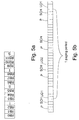
frames. Figure 5a illustrates the structure of such a multiframe as a
simplified diagram. These multiframes are used in the implementation of
logical channels. The multiframe is divided into 12 radio blocks (RB0-RB11),
each of which includes four TDMA frames. One radio block is
needed to send one RLC/MAC frame. In addition, the multiframe includes
two so-called search frames (S), during which the base station of the cell
does not send on the logical packet data channel (PDCH). Then the mobile
stations in the area of the cell can perform measurements of the signal
strength and interference of the base stations of the adjacent cells. The
remaining two frames are reserved for the transmission (T) of the Packet
Timing Advance Channel (PTCCH).
Logical channels have been formed in the GPRS system for various
purposes of signalling and transmission of data packets. Of these logical
channels the following may be mentioned in this context: PCCCH (Packet
Common Control Channel), PBCCH (Packet Broadcast Control Channel),
PDTCH (Packet Data Traffic Channel), PACCH (Packet Associated Control
Channel) and PTCCH (Packet Timing Advance Channel). The PCCCH
channel is used, for instance, during a packet-switched connection to
request transmission periods from the base station for the transmission of
packets, to inform of the granted periods to the mobile station, to send
search messages etc. In the PBCCH channel, the base station sends
system information of the packet system to the mobile station. The
transmission of data packets is carried out in the PDTCH channel. The
PACCH channel is used for the transmission of signalling information
related to the transfer of packets (acknowledgements, measurement
information and reports). The PTCCH channel is used in connection with
timing for evaluating different delays.
In the transmission stage, the bits formed from the packets, possibly coded,
are not transferred to the bursts as such, but they are interleaved and
matched at first. By interleaving, the bits are divided into four bursts so that
bits of one byte are not all placed in the same burst, but preferably in all four
bursts in a certain order. This order of interleaving is known in the receiver,
and thus it is possible to return the order of the bits. The purpose of
matching is to place the interleaved bits in the desired points in each burst
so that bits remain in the bursts for other purposes (stealing bits), such as
for transmitting channel coding information or other control information.
Data transfer on the lowest level between the base station subsystem BSS
and the serving GPRS support node is carried out in the L2 layer (data link
layer), in which a link layer protocol, such as the known LAPD protocol,
frame relay protocol or the like is used. The L2 layer can also include quality
or routing information according to the GPRS specifications. The L2 layer
has properties of the physical layer and data link layer of the OSI model.
Above the MAC layer, there is the RLC layer (Radio Link Control), the
purpose of which is to divide the data frames formed by the LLC layer into
packets of a certain length that can be sent to the radio path (PDU, Protocol
Data Unit), to transmit them and retransmit them, when necessary. The
length of the packets in the GPRS system is the length of one GSM time slot
(approx. 0.577 ms).
The LLC layer (Logical Link Control) offers a reliable data transfer link
between the mobile station 2 and the serving GPRS support node SGSN.
Among other things, the LLC layer adds error check information to the
message to be transmitted. Based on this information, attempts can be
made to correct incorrectly received messages, and the message can be
retransmitted, when necessary. In addition, the encryption and decryption of
the information is carried out in the LLC layer.
The functions carried out in the SNDCP layer (Sub-Network Dependent
Convergence Protocol) include protocol changes of the information to be
transmitted, compressing, segmentation and the segmentation of messages
coming from an upper level. The structure of a SNDCP frame is also shown
in Fig. 2. The SNDCP frame comprises a SNDCP header field and a
SNDCP data field. The SNDCP header field consists of protocol information
(Network Service Access Point Identity, NSAPI) and SNDCP control
information, such as compressing, segmentation and encryption
specifications. The SNDCP layer functions as a protocol adapter between
the protocols used on the upper level and the protocol of the LLC layer (data
link layer).
The information to be transmitted comes preferably as data packets
according to a suitable protocol, such as Packet Data Protocol (PDP), to the
SNDCP layer from an application, like messages according to the X.25
protocol or the Internet protocol (IP). The application can be, for example, a
data application of a mobile station, a telefax application, a computer
program, which has a data transfer connection to a mobile station, etc.
The SNDCP frame is transferred to the LLC layer, where an LLC header
field is added to the frame. The LLC header field consists of, for example,
the LLC control part, which defines the number of the frame and the type of
the command (info, acknowledgement, retransmission request, etc.) In
connection with the attachment to the GPRS packet network, the mobile
station sends an attach request message to the serving GPRS support
node. On the basis of the International Mobile Station Identity (IMSI) of the
mobile station, the serving GPRS support node can retrieve information
from the home location register HLR corresponding to the mobile station in
question, whereby the serving GPRS support node can use this information
to select a Temporary Logical Link Identity (TLLI) for a data transfer
connection. If the mobile station has used a TLLI before, it can transmit the
TLLI in a request message, whereby the serving GPRS support node can
give this TLLI to the mobile station again, or allocate a new TLLI to it. The
serving GPRS support node SGSN transmits the selected TLLI to the
mobile station for use in a data transfer connection between the mobile
station and the serving GPRS support node. This TLLI is used in data
transfer to determine to which data transfer connection each message
belongs. The same TLLI may not be in use simultaneously in more than one
data transfer connection. When the connection has terminated, the TLLI
used in the connection can be given to a new connection to be established.
The operator of the packet-switched network has divided the cells of the
packet-switched network into Routing Areas, which can be used in
determining the location of the mobile station 2. Each routing area
comprises one or several cells. Then the Mobility Management operations of
the mobile station are used to keep record of the location and connection
status of the mobile stations in the operation area of the packet-switched
network. These records are maintained both in the mobile station and the
packet-switched network, preferably the serving GPRS support node SGSN.
In the GSM system, the base station, which has a communications
connection to the mobile station 2, is changed in connection with the
reselection of a cell.
When a mobile station 2 is synchronized to the transmission of a cell in
connection with start-up or when a mobile station moves to the area of
another cell, the base station BTS sends information concerning, for
example, the way that logical channels in the area of the cell in question are
arranged in physical channels, or in which radio block and time slot of the
multiframe information of each logical channel is transmitted.
The packet system divides the mobile stations 2 in the area of the cell into
so-called paging groups. Paging messages are then sent to each paging
group in a certain radio block of the PCCCH channel. In the GPRS system,
the division into paging groups is to advantage based on the International
Mobile Subscriber Identity, the number of paging channels available in a cell
and the number of paging blocks available in the paging channel.
In cellular networks based on Code Division Multiple Access (CDMA) it is
possible to communicate to the mobile station 2 via several base stations
simultaneously. The base stations transmit a spread spectrum signal on a
so-called pilot channel, whereby a mobile station can conclude on the basis
of these pilot signals, which base station sends the best signal for
communication. The base stations which are currently communicating with
the mobile station 2 form a so-called active set. The movement of the mobile
station by means of the packet-switched network of the CDMA system can
be concluded from the changing of these active sets.
A mobile station in a GPRS system can have, among other things, the three
following connection modes in relation to the packet-switched network: an
idle mode (IDLE), a standby mode (STANDBY) and an active mode
(READY). In the idle mode, the mobile station is not connected to the
mobility management of the network and communication is not possible.
The mobility management information of the mobile station 2 and the
mobility management information of the serving GPRS support node
concerning the mobile station 2 in question is not necessarily up to date, if
the mobile station has moved to the area of another cell while in the idle
mode. When required, the mobile station 2 performs the selection and
reselection of a cell in the Public Land Mobile Network (PLMN) and the
packet-switched network. In relation to the packet-switched network, a
mobile station 2 in the idle mode is not connected to the network
In the active mode the mobile station is connected to the mobility
management of the packet-switched network, the location of the mobile
station is known in the packet-switched network with the accuracy of a cell,
and the mobile station can both send and receive data packets. The
selection and reselection of a cell in the packet-switched network is
performed by either the mobile station 2, or the packet-switched network
can control the selection of a cell. The header field of the Base Station
Subsystem GPRS Protocol (BSSGP) packet includes the cell identification
information. The purpose of the GPRS protocol level of this base station
subsystem in a system based on the packet-switched network described
here is to transmit information related to the routing and the Quality of
Service (QoS) between the Base Station Subsystem (BSS) and the serving
GPRS support node SGSN.
In the active mode, the mobile station is connected to the mobility
management of the packet-switched network, but the mobile station cannot
send or receive data packets. The location of the mobile station in the
packet-switched network is known only with the accuracy of the routing
area. The reception of paging requests from the serving GPRS support
node for cell selection (CS) services is possible. Moving from the active
mode to the standby mode can be done when, for example, a sufficiently
long time has passed since the transmission of the last data packet between
the mobile station and the packet-switched network. A mobile station 2 in
the standby mode can start either activation or deactivation of a packet-switched
connection (PDP). The status of the packet-switched connection
must be updated before sending or receiving data packets. If a packet-switched
connection has been activated, the serving GPRS support node
can receive packets. Then the serving GPRS support node SGSN sends a
paging request to the routing area where the mobile station 2 is located.
When the mobile station 2 sends a reply message to this request, the
connection mode of the mobile station 2 is changed into the active mode.
The connection mode of the serving GPRS support node SGSN is changed
into the active mode after it has received a reply message to a paging
request from the mobile station 2. The connection mode of the mobile
station 2 is changed from the standby mode to the active mode also when
the mobile station sends data packets or signalling information to the
serving GPRS support node SGSN. In a corresponding manner, in the
serving GPRS support node SGSN the change of the connection mode from
the standby mode to the active mode is also done in the situation that the
SGSN receives data packets sent by the mobile station 2, or signalling
information.
The mobile station receives paging messages from the base station it is
listening to at the time. From these paging messages the mobile station can
find out whether there are transmissions coming to it from the base station.
The time between two consecutive paging messages is called a DRX period
(discontinuous reception). Later in this specification, this DRX period will be
called a paging period. During a paging period, the mobile station can set
itself to a power saving mode for a certain time, because it does not expect
to be getting any transmissions from the mobile communication network.
Such a discontinuous reception mode (DRX mode) is allowed for a mobile
station in a standby mode in all other times except when the mobile station
is performing cell selection functions. The length of the period can vary, and
the mobile station receives from the base station parameter information, on
the basis of which the mobile station can calculate when the next paging
message can be expected. Because the mobile station is synchronized to
the base station transmission, the mobile station knows the transmission
time of the next paging message. A discontinuous reception mode like this
enables switching all possible functional blocks connected with the radio
interface off when they are not needed. Functional blocks like this are, for
example: the radio part, the baseband part, which preferably also comprises
a digital signal processing unit, and a system oscillator used in the radio
interface functions. The purpose of this arrangement is to reduce the overall
power consumption of the mobile station.
However, the mobile station must change from the idle mode back to the
standby mode at times for receiving the above mentioned paging messages,
for example. In the GPRS system, the maximum length of the idle mode is
specified as a time corresponding to 64 52-multiframes, or approx. 15 s.
Then the maximum delay for establishing a connection with the mobile
station is approx. 15 seconds. However, in practical applications the
maximum length of the idle state is made much shorter, nine 52-multiframes,
or approx. two seconds, because of the specifications of the
GSM system and the fact that the frequency stability of an oscillator used in
the idle state may not be sufficient to keep the mobile station synchronized
to the mobile communication network. If a prior art mobile station does not
keep synchronized to the mobile communication network during the idle
mode, this can mean that the mobile station cannot receive the next paging
message. On the other hand, the power consumption of a mobile station is
generally the higher the shorter the idle period is.
It is an objective of the present invention to provide a method for reducing
power consumption in a mobile station, a system in which the method is
applied, and a mobile station. The method according to the present
invention is characterized in what is set forth in the characterizing part of
Claim 1. The system according to the present invention is characterized in
what is set forth in the characterizing part of Claim 13. The mobile station
according to the present invention is characterized in what is set forth in the
characterizing part of Claim 20. The invention is based on the idea that in
order to save power, the duration of the idle mode is increased by
lengthening the paging period. In the solution according to the invention, this
is enabled by either carrying out synchronization functions in the mobile
station during the paging period or by carrying out the synchronization of the
mobile station before the reception of the next paging message.
The present invention provides considerable advantages as compared to
the prior art solutions, packet-switched networks and mobile stations. The
method according to the invention reduces the power consumption of the
mobile station, because the period when the radio interface functions are on
can be shortened in the standby mode. In addition, it is not necessary for
the mobile station to perform measurements as often as it is required in the
prior art mobile stations during the idle mode.
In the following, the invention will be described in more detail with reference
to the accompanying drawings, in which
- Figure 1
- illustrates the logical structure of the GPRS system as a
simplified block diagram,
- Figure 2
- illustrates the layered structure of the GPRS system and the
data frame structure of the layers in a simplified manner,
- Figure 3
- illustrates the functioning of a method according to the first
preferred embodiment of the invention as a simplified flowchart,
- Figure 4
- illustrates the functioning of a method according to the second
preferred embodiment of the invention as a simplified flowchart,
- Figure 5a
- illustrates the multiframe structure according to the GPRS
system in a simplified manner,
- Figure 5b
- illustrates the timings of the method according to the second
preferred embodiment of the invention by means of multiframes,
- Figure 6
- shows a mobile station according to a preferred embodiment of
the invention as a simplified block diagram, and
- Figure 7
- shows a simplified block diagram of a receiver, which can be
used in connection with the mobile station according to the
invention.
In the following, the invention is described with reference to the packet-switched
service GPRS implemented in the GSM system, but the invention
is not limited to this system only. The invention can also be applied in the
UMTS system being developed, and in other mobile communication
systems of the third generation.
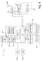
Fig. 6 shows a simplified block diagram of a mobile station 2 according to a
preferred embodiment of the invention. The mobile station 2 preferably
comprises mobile station functions and data processing functions, for which
the mobile station 2 can have dedicated user interfaces 33, 34. In order to
arrange data transmission to the mobile communication network 4, the
mobile station 2 comprises a high-frequency part 38, which includes, among
other things, a transmitter (not shown) and a receiver. The mobile station 2
also includes audio devices 35, such as an earphone and a microphone. In
a mobile station 2 according to Fig. 6, the processor 25 (MPU) and the
digital signal processing unit 32 (DSP) are implemented by means of an
Application Specific Integrated Circuit (ASIC) 36. An ASIC circuit 36 also
comprises other functions, such as control logic (LOGIC), memory 26
(MEM) and input/output logic (I/O). The memory devices 26 of a mobile
station 2 can also comprise external memory 37. The clock signals and the
like needed in the operation of the mobile station 2 are generated with the
first oscillator OS1 and/or the second oscillator OS2.
Fig. 7 also shows a simplified block diagram of a receiver RX, which can be
used in connection with the mobile station 2 according to the invention. In
the receiver RX, signals are received with an antenna ANT and conducted
via an antenna switch 29 to the pre-stage 30 of the receiver, in which pre-stage
the received signal is, among other things, band-pass filtered and
transformed either as direct transformation or via one or more intermediate
frequencies to a baseband signal. The transformation is carried out in a
manner known as such by mixing one or more local oscillator frequencies to
the received signal. The local oscillator frequencies are generated
preferably with the first oscillator OS1 in the standby mode and preferably
with the second oscillator OS2 in the active mode.
The signal received from the pre-stage 30 is conducted for detection to the
detector 31. The detector 31 forms an analog signal, which is converted to a
digital signal in the Analog-to-Digital Converter (ADC) 19. After this, the
digitized signal is conducted to the digital signal processing unit 32.
In the digital signal processing unit 32, it is also possible to calculate the
strength of the received signal from the detected signal formed by the
detector 31. For measuring the signal-to-noise ratio (SNR), the strength of
the noise and other interfering signals is preferably also measured in
addition to the strength Rx of the received signal, whereby the signal-to-noise
ratio is obtained as the ratio of these measurement results. The
strength of the noise can be measured in an idle period, for example,
preferably in the idle period preceding the reception period. The processor
25 of the mobile station then gives the digital signal processing unit 32 the
information that the received signal is not a useful signal but a spurious
signal. Then the digital signal processing unit 32 calculates the strength of
the noise on the basis of the signal formed by the detector 31, whereby the
signal-noise ratio SNR can also be calculated. Obviously the strength of the
received signal Rx and the signal-to-noise ratio SNR can also be
determined with other methods known as such than the ones described
here.
In the reception mode, e.g. during the active mode or the standby mode, the
receiver RX of the mobile station 2 thus listens with the reception channel,
which has been notified to the mobile station 2 by the base station
subsystem BSS. The mobile station 2 receives bursts and carries out
operations that are reverse to the transmission stage. The bursts are
demodulated in a demodulator 31, whereby a demodulated bit string is
formed. The next step is to remove the matching of the data bits in the
dematching block 15. The interleaving is removed in the arrangement block
16, whereby there is a bit string in the output of the arrangement block 16
corresponding to the coded and possibly clipped bit string of the
transmission stage in errorless reception.
When the bit string has been decoded, the reconstructed frame of the radio
connection can be moved in the mobile station 2 to upper levels in the
protocol stack 23, in a manner known as such, whereby the received
information is available for the application 24.
The so-called GPRS attach signalling is performed when the mobile station
2 attaches to the packet-switched network, after switching on, for example.
This is also performed when the mobile station changes from the idle mode
to the active mode. The purpose of the GPRS attach is, among other things,
to inform the packet-switched network 4 of the readiness of the mobile
station 2 to packet-switched connections, and to select a suitable paging
period. This selection of the paging period can preferably be carried out so
that the mobile station 2 selects a paging period, preferably the maximum
(64 multiframes). Information of the selected paging period is sent from the
mobile station 2 in an ATTACH_REQUEST message to the packet-switched
network 4, where it is examined whether the suggested paging period can
be taken into use. If the packet-switched network 4 supports the suggested
paging period, it sends information about this (SPLIT_PG_CYCLE) to the
mobile station 2 in an ATTACH_RESPONSE message. But if the packet-switched
network 4 does not support the suggested paging period, it selects
a paging period available in the packet-switched network 4 and sends
information about the selected paging period in a response message. After
the paging period has been selected, this value is saved in the mobile
station 2 and the packet-switched network 4. In connection with the attach
signalling, the mobile station 2 is also notified in which time slots paging
messages are sent to the mobile station 2.
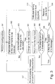
In the following, the operation of the method according to the first preferred
embodiment of the invention in the mobile station 2 will be described in
more detail with reference to the flow chart of Fig. 3 and the frames of Fig.
5b. It is assumed that the mobile station 2 has performed the attachment to
the mobile communication network, and a paging period has been selected
for the mobile station 2. After the attachment, the mobile station 2 has
received from the packet-switched network, preferably in the PCCCH
channel, information about the location of the paging message to be sent to
the mobile station 2 in the multiframe (block 301). This radio block used by
the PCCCH channel is marked with the letter P in Fig. 5b. In addition, the
marking UD1 is used in Fig. 5b to denote the paging messages, which are
intended for reception by the group to which the mobile station 2 belongs.
Correspondingly, paging messages intended for other groups are marked
UD2 in Fig. 5b.
When a mobile station 2 changes from the active mode to the standby
mode, the digital signal processing unit 32 preferably calculates how many
time slots there are before the next reception time slot allocated to the
mobile station 2, or when the next paging message UD1 will be sent in the
packet-switched network to the mobile station 2 (block 302). The digital
signal processing unit 32 examines whether the time before the next frame
is so long that it is possible to set the mobile station 2 in the idle mode
(block 303). If the time is not sufficient for changing to the idle mode, the
mobile station stays in the standby mode for receiving the information to be
sent in the next reception time slot. If the time is sufficient for setting to the
idle mode, the mobile station 2 is set to the idle mode.
In order to start the idle mode, a time control is set by means of a timer T1
(Fig. 6) in connection with the digital signal processing unit 32, for example.
The purpose of the time control is to interrupt the idle mode in order to
perform synchronization, as will be explained later in this specification. After
this, the mobile station 2 is set to the idle mode (block 304), whereby the
digital signal processing unit 32 changes to an idle mode, and the input
voltage is switched off from the high-frequency part and the second
oscillator O2, for instance. In the idle mode, the digital signal processing unit
32 does not perform the program code, but the timer T1, for example, is in
operation. In the idle mode of the mobile station 2, the required timings are
created with the first oscillator O1, the frequency of which is, for example, 32
kHz. The maximum length of the idle mode in this preferred embodiment is
nine multiframes, whereby it is also possible to keep the mobile station 2
synchronized to the packet-switched network by means of the first oscillator
O1, in a manner known as such. Obviously the numerical values presented
here only serve as examples which illustrate the invention, but do not
constitute a limitation thereof.
After the time set in the time control has expired, the timer T1 creates an
interrupt signal or a corresponding excitation to the digital signal processing
unit 32. As a result of this, the digital signal processing unit changes to the
normal operation mode (block 305) in order to perform the following
measures, among other things. The digital signal processing unit 32
examines (block 306) whether the paging period in use is longer than the
threshold value set in advance, preferably nine multiframes in a packet-switched
network according to the GPRS system.
If the paging period is shorter or as long as the threshold value, the digital
signal processing unit 32 sets the high-frequency part of the mobile station
in operation for receiving the paging message UD1 intended for the mobile
station 2 in a manner known as such (block 307). This includes starting the
second oscillator O2, for instance. The mobile station 2 can be kept as
synchronized to the packet-switched network preferably so that the burst
used in the transmission of the paging message UD1 comprises a training
sequence in a known manner, and the timing error can be calculated in the
digital signal processing unit 32 by examining the training sequence. The
training sequence preferably comprises 26 bits, which are sent in the middle
of the burst. In addition to the reception of the paging message, the mobile
station 2 can perform signal strength measurements, for example. After this,
the operation continues from block 302.
If the paging period is set longer than the threshold value, it is examined in
block 308 if the idle mode has been interrupted because the paging period
has expired and a paging message UD1 is coming to the mobile station 2.
Then the operation moves to block 307, reception of the paging message
UD1. If the paging period has not ended yet, the burst is received in the
PCCCH channel P (block 309). The digital signal processing unit 32
performs calculation needed for the correction of timing errors (block 310)
from the training period of this burst. The timing of the mobile station 2 is
changed according to the result of the calculation. After this, operation
continues from block 302.
The operations described above can also be largely implemented in the
application programs of the signal processing unit 32. Some changes may
also be needed in the algorithms and filters used in the calculation of the
timing error, because in the prior art mobile stations it is assumed that the
error is calculated on the basis of the reception of two or four bursts.
The operation of a method according to another preferred embodiment of
the invention will be described in the following with reference to the flow
chart in Fig. 4. The operation of blocks 401, 402, 403, 404 and 405 largely
corresponds to the operation of the corresponding blocks 301, 302, 303,
304 and 305. However, in block 404, a longer period of time is set as the
length of the idle mode than in the method according to the first
embodiment. In order to calculate the length of the idle state, it has to be
discovered when the next paging message UD1 will be sent and in which
frame before this paging period a synchronization burst will be sent in the
SCH channel. In addition, the maximum inaccuracy of the first oscillator O1
must be taken into account and the length of this idle state must be
shortened to such an extent that the mobile station 2 changes to the
reception of the synchronization burst in time in spite of the inaccuracy.
When the transmission moment of the synchronization burst is known, time
control can be set. In the next step, the mobile station 2 changes to the idle
state.
The idle state ends when the time control has ended in block 405, whereby
the mobile station 2 is set to the reception mode. Then the mobile station 2
attempts to detect the transmission of a synchronization burst (block 406). If
the reception of the synchronization burst SCH succeeds, the mobile station
2 can be synchronized to the multiframe of the packet-switched network
again (block 407). After this, the digital signal processing unit 32 calculates
the time of the next paging message UD1 (block 408) and examines in block
409 if the time is sufficient for changing to the idle mode. If the time is long
enough for changing to the idle mode, the digital signal processing unit 32
starts the time control and sets the mobile station in the idle mode (block
410). If the time is not sufficient for changing to the idle mode, the mobile
station stays in the normal standby mode until the reception of the next
paging message.
If the mobile station was set in the idle mode in block 410 above, it is
stopped by time control for the duration of the reception of the burst to be
sent in the PCCCH channel P (block 411), as was described earlier in this
specification. Block 412 represents the reception of the paging message
and the performance of the measurements.
The functional features described above can be largely implemented by
means of software in the currently known mobile stations 2.
This method according to the second preferred embodiment of the invention
enables reducing power consumption even more than the method according
to the first embodiment of the invention, especially when using longer
paging periods, because the idle mode is then interrupted less frequently.
In the following, the operation of the method according to still another
preferred embodiment of the invention in the mobile station 2 will be
described in more detail. This preferred embodiment is based on the idea
that the selection of the paging period is affected by the strength of the
received signal of the base station BTS with which the mobile station 2 is in
connection. The mobile station 2 begins to perform measurements of the
strength of the received signal of the base station advantageously after the
packet idle mode is configured at the attachment.
It is assumed that the mobile station 2 has performed the attachment to the
mobile communication network, and a paging period has been selected for
the mobile station 2. Further, it is assumed that there are two different
paging periods from which the paging period can be selected. However, this
invention is not restricted to two different paging periods but it can also be
applied in systems where more than two paging periods can be used. One
of the selectable paging periods can be defined as a default paging period,
which is selected in connection with the attachment of the mobile station 2
to the mobile communication network.
The signal strength measurements are preferably performed by taking
samples from the received signal at regular intervals. The samples are
taken e.g. during the PBCCH-frames P (or BCCH-frames) which the base
station transmits. The measured signal strength values are then filtered by
using a suitable filter to define a representation of the signal, e.g. an
average signal strength or a variance of samples taken from the received
signal. Also so called C value which will be measured by a mobile station of
the GPRS-system can be used to define the representation of the signal.
The average signal level is preferably a running average value, i.e. the
average signal strength value is calculated by using the newest
measurement value and a certain number (N) of previous values, which are
stored in the mobile station 2. The mobile station 2 comprises a circular
buffer in which the average values are stored after every measurement.
When the buffer is full, the newest average value is written on the oldest
one.
It is not necessary to perform the signal strength measurement every time
the base station transmits the PBCCH-frame P. For example, the
measurement interval, i.e. time between two successive measurements, can
be defined the same as the paging period. In addition to that a maximum
measurement interval could be defined, wherein the measurement is
performed e.g. once per paging period, if the paging period is not longer
than said maximum measurement interval, or the measurement interval is
substantially the same as said maximum measurement interval, if the
paging period is longer than said maximum measurement interval. It is also
possible that the mobile station uses more than one sample during the
frame and calculates an average value of received signal strength by using
those samples. This average value is then used as the received signal
strength value for that frame.
The parameters related to the filtering need to be defined in practical
implementations of the present invention. These parameters include the
length of the filter and values of the filter taps. The timing window, i.e. the
number of previous values which are used in the filtering, is dependant on
the measurement interval of the received signal. For example, if the
reference signal is BCCH carrier and maximum measurement interval is
defined as 4s, the length is related to Min(current paging period, 4s)
because only one sample/Min(current paging period, 4 s) is taken from the
BCCH carrier. In this embodiment of the present invention also an received
signal level window is defined for tracking the magnitude of changes in the
representation of the received and measured signal. This window defines
the upper and lower limits within the representation of the signal shall be in
order to activate a change to a longer paging period, if not longest already,
or in order to activate a change to a shorter paging period, if not shortest
already, if the limits are crossed. The upper and lower limits are preferably
defined by one ore more threshold values (in dB) above and under the
previous value of the representation of the signal. The threshold values may
be changed according to the reception level of the signal and/or according
to the quality of the reception of the mobile station 2. In a situation where
more than two different paging periods are supported there may be several
steps towards the longest or towards the shortest paging period. Therefore
in such a case the threshold values also depend on the length of the current
paging period. If more than two paging periods are supported the amount of
the change could also be defined for the changes of the paging period.
If the measurement is to be performed when the mobile station 2 is in the
idle mode, at least part of the functions of the mobile terminal 2 have to be
set in operation for the measurement. This can advantageously be
implemented so that the digital signal processing unit 32 calculates the time
when the base station BTS transmits PBCCH-frames. Then, the digital
signal processing unit 32 starts a timer which informs the digital signal
processor 32 of the correct measurement time. After the timer is started the
mobile station 2 can be set to the idle mode. Also the digital signal
processor can set itself to idle mode. Therein when the timer reaches the
set timing value it will cause an interrupt to the digital signal processor 32
and the digital signal processor is set to normal operating mode.
To perform the measurement, at least the receiver RX of the high-frequency
part is powered on. The digital signal processor 32 can now measure the
received signal strength e.g. from the output of the Analog-to-Digital
Converter 19 and calculate a new average value using at least part of the
previously calculated and stored average values. When the calculation is
performed the newest average value is compared with the stored average
values. If the difference between the newest average value and any of the
stored average values is greater than a first threshold value X, the paging
period is not changed. If the difference between the newest average value
and all of the stored average values is not greater than said first threshold
value X and the present paging period is not the longest one, the change of
the paging period is triggered. Now the mobile station 2 and the network
begins to negotiate for a longer paging period.
When the longer paging period is selected for the idle mode, the mobile
terminal according to this advantageous embodiment operates as follows.
The mobile terminal preferably performs the signal strength measurements
periodically during the PBCCH-frames P (or BCCH-frame) and an average
signal strength is calculated, preferably as a running average value as
mentioned above. Again a certain number (M) of previously calculated
average values are stored in a circular buffer of the mobile station 2. The
mobile station 2 can use the same circular buffer than before, or it can use
another circular buffer for the longer paging period. Now, the number of the
saved values preferably is less than if shorter paging period were selected,
i.e. M<N. The values of the circular buffer are initialized by using the old N
average values which were calculated during the previous (shorter) paging
period, if available.
Every time the average value is updated it is checked whether the new
average value of the signal strength differs more than a second threshold
value from any of the stored average values. If the new average value is
within said second threshold value from the stored values, the paging period
is not changed. However, if there is even one value which differs more than
said second threshold value from the new value, the change of the paging
period is triggered. Now, the mobile station 2 and the network begin to
negotiate for a shorter paging period.
The first threshold value X defines the size of the received signal strength
window during the first paging period. The second threshold value Y defines
the size of the received signal strength window during the second paging
period. The size of the windows may vary according to the quality (e.g.
pseudo bit error rate) and the level (e.g. in dBm) of the reception. The better
the quality or the higher the level, the bigger the threshold value X, Y may
be. There can also be more than two paging periods to be selected and
more than two threshold values defined.
The method can also comprise a hysteresis time to avoid a situation in
which the mobile station 2 begins to oscillate between two paging periods.
This could happen if the signal strength is varying. This can be avoided or at
least limited in such a way that every time the paging period is changed the
mobile station 2 waits the hysteresis time before is starts to perform the
comparison of the new value and the stored values. For example, the
comparison is started when 2*N measurements are performed after the last
change of the paging period. The value of the hysteresis time can also be
variable. The value may vary according to the previous packet transfer
mode (packet transfer/idle) of the mobile station 2.
When a mobile station 2 changes from the active mode to the idle mode first
time after attaching to the network, the mobile station 2 preferably selects
the default paging period and starts to negotiate for the paging period with
the network. When a mobile station 2 changes from the active mode to the
idle mode and the mobile station 2 has already been in idle mode, the
mobile station 2 checks which paging period was previously in use when the
mobile station 2 was in the idle mode and selects it.
The circular buffer(s) can be implemented e.g. in the memory means 37 of
the mobile station 2, in the memory 26 of the Application Specific Integrated
Circuit 36 or as a separate memory block, which is known as such.
When the paging period is changed and the quality of the reception
substantially decreases, then preferably the previous paging period is
restored. Quality measures are preferably based on paging blocks for the
mobile station 2 or BCCH/PBCCH frame reception.
The method presented above has an advantage that it takes into account
the quality and strength of the received signal wherein in good signal
conditions the paging period can be increased and further power savings
achieved because the mobile station 2 can stay longer in idle mode.
The method presented above is preferably initialized every time when the
mobile station 2 enters the idle mode. The method can be disabled if the
network does not support the negotiation of the paging period parameters. It
is also possible that the user of the mobile terminal can enable and disable
the method.
It is also possible to use other criteria than the signal strength of the
received signal in connection with the selection of the paging period with the
above described another preferred embodiment of the invention. Such other
criteria could be, for example, average number of errors or variance. The
variance can be calculated, for example, by using the received signal
strength of N previous paging blocks, or by using N previous samples which
are taken e.g. during the PBCCH-frames P (or BCCH-frames). Further, it is
possible to calculate the variance by averaging variances of paging block
bursts.
There is still another alternative embodiment of the invention which allows
the user of the mobile station to select the paging period. For example, two
different operating modes are defined and the user may select the correct
one. Those operating modes could comprise e.g. "in office" and "on the
road". The first one is normally quite stable environment, where the cell
coverage is normally good. This means that the mobile station will with a
high probability receive correctly all the blocks intended to that mobile
station. When the downlink connection is good the paging period can be
increased. This will reduce the power consumption of the mobile station.
The other operating mode is intended for environments where signal
conditions are continuously changing e.g. because the movement of the
mobile station. This causes changes to the reception conditions and
probably some of the pagings are missed due to the erroneous reception. In
this kind of environments there is a limit for the largest paging period, which
is smaller than in the office environment. The smaller paging period will
increase the power consumption but this needs to be done to ensure
reliable idle mode operation.
The user controlled paging period can also be related to preferred service.
For example, when circuit switched calls are preferred, a smaller paging
period is selected and when the packer transfer is preferred, a larger paging
period is selected.
The power saving achieved with the method according to the invention can
be assessed by using the following calculations. The following assumptions
have been made in the calculations:
- reception of a paging message: 4 TDMA frames
- reception of a burst from the PBCCH/PCCCH channel: 1 TDMA frame
- exiting the idle mode: 1 TDMA frame
- performing the measurements/paging period: 5 TDMA frames
- the FDDH, SCH or BCCH frames of the adjacent cells not received
In a prior art method, when the paging period is nine multiframes, the non-idle
time of the mobile station is calculated as follows:
| 1. exiting the idle mode | 1 frame |
| 2. reception of a paging message | 4 frames |
| 3. performing the measurements | 5 frames |
| 4. changing to the idle mode for 458 frames |
The previous steps are repeated eight times during 64 multiframes, whereby
the mobile station is not in the idle mode for the duration of 80 (= 8*(1+4+5))
frames.
A reference value for the method according to the first preferred
embodiment of the invention is obtained as follows:
| 1. exiting the idle mode: | 1 frame |
| 2. reception of a paging message: | 4 frames |
| 3. performing the measurements: | 5 frames |
| 4. changing to the idle mode for the duration of 458 frames |
| 5. exiting the idle mode: | 1 frame |
| 6. reception of a PCCCH burst and calculation of a timing correction | 1 frame |
| 7. changing to the idle mode for the duration of 466 frames |
| 8. the steps 5, 6 and 7 are repeated until the end of the paging period, after which the steps 1 to 4 are also repeated. |
The reception of the paging message and the measurements (1+4+5=10
frames) are carried out only once at the beginning of each paging period,
after which the mobile station exits the idle mode only for determining the
timing correction after each nine multiframes. During the whole period of 64
multiframes, timing corrections are preferably carried out seven times, which
means 14 frames (=7*(1+1)). The whole time during which the mobile
station is not in the idle mode during the period of 64 multiframes is thus 24
frames, which is a considerably shorter time than that of the prior art mobile
station. The calculations above were based on the fact that the reception
and decoding of a paging message require the reception of four bursts. If
the reception and decoding of the paging message can be carried out from
two bursts, the corresponding times are 64 frames in a prior art receiver and
22 frames in a mobile station applying a method according to the first
preferred embodiment of the invention.
A reference value for the method according to the second preferred
embodiment of the invention is obtained as follows:
| 1. exiting the idle mode: | 1 frame |
| 2. reception of a paging message: | 4 frames |
| 3. performing the measurements: | 5 frames |
| 4. changing to the idle mode for the duration of 3316 frames |
| 5. exiting the idle mode: | 1 frame |
| 6. reception of a SCH burst and calculation of a timing correction | 1 frame |
The reception of the paging message and the measurements (1+4+5=10
frames) are carried out only once at the beginning of each paging period,
after which the mobile station exits the idle mode only a little before the end
of the paging period for determining the timing correction. The whole time
during which the mobile station is not in the idle mode during the period of
64 multiframes is thus 12 frames, which is even a shorter time than that of a
mobile station applying a method according to the first embodiment of the
invention.
In a GPRS system, the maximum period between measurements can be set
as four seconds, for example. Then the values mentioned above become
somewhat different. A reference value for the method according to the first
preferred embodiment is then obtained as follows:
| 1. exiting the idle mode: | 1 frame |
| 2. reception of a paging message: | 4 frames |
| 3. performing the measurements: | 5 frames |
| 4. changing to the idle mode for the duration of 458 frames |
| 5. exiting the idle mode: | 1 frame |
| 6. reception of a PCCCH burst and calculation of a timing correction | 1 frame |
| 7. changing to the idle mode for the duration of 466 frames |
| 8. exiting the idle mode: | 1 frame |
| 9. measurements and the reception of one PCCCH burst: | 8 frames |
| 10. changing to the idle mode for the duration of 459 frames |
Steps 5 to 10 are repeated three times during 64 multiframes. At the last
time in step 10, the idle mode is nevertheless shorter than 459 frames. The
above gives a total of 10+3*(1+1+1+8)=43 frames, during which the mobile
station is not in the idle mode, when the reception of the paging period is
carried out from four bursts.
Correspondingly, a reference value for the method according to the second
preferred embodiment of the invention is obtained in this situation as
follows:
| 1. exiting the idle mode: | 1 frame |
| 2. reception of a paging message: | 4 frames |
| 3. performing the measurements: | 5 frames |
| 4. changing to the idle mode for the duration of 856 frames |
| 5. exiting the idle mode: | 1 frame |
| 6. measurements without the reception of a PCCCH burst: | 8 frames |
| 7. changing to the idle mode for the duration of 857 frames |
| 8. exiting the idle mode: | 1 frame |
| 9. reception of a SCH burst and calculation of a timing correction | 1 frame |
Steps 5, 6 and 7 are repeated three times during 64 multiframes. At the last
time in step 7, the idle mode is nevertheless shorter than 857 frames. The
above gives a total of 10+3*(1+8)+1+1=39 frames, during which the mobile
station is not in the idle mode, when the reception of the paging message is
carried out from four bursts.
Even in these latter situations, a mobile station according to the present
invention is in a not-idle state for a time, which is about half of the
corresponding time in the prior art mobile stations.
The present invention is not limited to the above described embodiments
only, but it can be varied within the scope defined by the attached claims.