EP1107473A2 - Variable CDMA transmission power control cycle - Google Patents
Variable CDMA transmission power control cycle Download PDFInfo
- Publication number
- EP1107473A2 EP1107473A2 EP00125357A EP00125357A EP1107473A2 EP 1107473 A2 EP1107473 A2 EP 1107473A2 EP 00125357 A EP00125357 A EP 00125357A EP 00125357 A EP00125357 A EP 00125357A EP 1107473 A2 EP1107473 A2 EP 1107473A2
- Authority
- EP
- European Patent Office
- Prior art keywords
- transmission power
- power control
- doppler frequency
- control period
- signal
- Prior art date
- Legal status (The legal status is an assumption and is not a legal conclusion. Google has not performed a legal analysis and makes no representation as to the accuracy of the status listed.)
- Withdrawn
Links
- 230000005540 biological transmission Effects 0.000 title claims abstract description 224
- 238000005562 fading Methods 0.000 claims description 41
- 238000012935 Averaging Methods 0.000 claims description 27
- 230000008859 change Effects 0.000 claims description 25
- 238000000034 method Methods 0.000 claims description 22
- 238000010295 mobile communication Methods 0.000 claims description 22
- 230000002452 interceptive effect Effects 0.000 claims description 14
- 230000002159 abnormal effect Effects 0.000 claims description 11
- AKUNSPZHHSNFFX-UHFFFAOYSA-M tributyl(tetradecyl)phosphanium;chloride Chemical compound [Cl-].CCCCCCCCCCCCCC[P+](CCCC)(CCCC)CCCC AKUNSPZHHSNFFX-UHFFFAOYSA-M 0.000 description 17
- 238000004891 communication Methods 0.000 description 5
- 238000004904 shortening Methods 0.000 description 3
- 230000015572 biosynthetic process Effects 0.000 description 2
- 238000010586 diagram Methods 0.000 description 2
- 230000004044 response Effects 0.000 description 2
- 230000035945 sensitivity Effects 0.000 description 2
- 238000003786 synthesis reaction Methods 0.000 description 2
- 230000003247 decreasing effect Effects 0.000 description 1
- 230000002542 deteriorative effect Effects 0.000 description 1
- 230000005684 electric field Effects 0.000 description 1
- 239000000284 extract Substances 0.000 description 1
- 230000006872 improvement Effects 0.000 description 1
- 230000008569 process Effects 0.000 description 1
- 230000007480 spreading Effects 0.000 description 1
Images




Classifications
-
- H—ELECTRICITY
- H04—ELECTRIC COMMUNICATION TECHNIQUE
- H04W—WIRELESS COMMUNICATION NETWORKS
- H04W52/00—Power management, e.g. Transmission Power Control [TPC] or power classes
- H04W52/04—Transmission power control [TPC]
- H04W52/06—TPC algorithms
- H04W52/14—Separate analysis of uplink or downlink
-
- H—ELECTRICITY
- H04—ELECTRIC COMMUNICATION TECHNIQUE
- H04W—WIRELESS COMMUNICATION NETWORKS
- H04W52/00—Power management, e.g. Transmission Power Control [TPC] or power classes
- H04W52/04—Transmission power control [TPC]
- H04W52/18—TPC being performed according to specific parameters
- H04W52/24—TPC being performed according to specific parameters using SIR [Signal to Interference Ratio] or other wireless path parameters
-
- H—ELECTRICITY
- H04—ELECTRIC COMMUNICATION TECHNIQUE
- H04W—WIRELESS COMMUNICATION NETWORKS
- H04W52/00—Power management, e.g. Transmission Power Control [TPC] or power classes
- H04W52/04—Transmission power control [TPC]
- H04W52/54—Signalisation aspects of the TPC commands, e.g. frame structure
-
- H—ELECTRICITY
- H04—ELECTRIC COMMUNICATION TECHNIQUE
- H04W—WIRELESS COMMUNICATION NETWORKS
- H04W52/00—Power management, e.g. Transmission Power Control [TPC] or power classes
- H04W52/04—Transmission power control [TPC]
- H04W52/06—TPC algorithms
- H04W52/08—Closed loop power control
-
- H—ELECTRICITY
- H04—ELECTRIC COMMUNICATION TECHNIQUE
- H04W—WIRELESS COMMUNICATION NETWORKS
- H04W52/00—Power management, e.g. Transmission Power Control [TPC] or power classes
- H04W52/04—Transmission power control [TPC]
- H04W52/06—TPC algorithms
- H04W52/14—Separate analysis of uplink or downlink
- H04W52/146—Uplink power control
Definitions
- This invention relates to a CDMA (Code Division Multiple Access) transmission power control method and system for carrying out a closed loop control for transmission power and, in particular, to a CDMA, transmission power control method and system that a base station carries out transmission power control for a mobile station.
- CDMA Code Division Multiple Access
- a base station can communicate with a plurality of mobile stations by using the same frequency band at the same time. That is, the base station receives a received signal including a plurality of reverse transmission signals transmitted from the mobile stations.
- the desired signal is affected by the undesired signal.
- the undesired signal is interference.
- a degree of the interference to the desired signal depends on a reception electric power (or a reception electric field strength) of the undesired signal. If the mobile stations carry out the transmission with the same transmission power, positions of the mobile stations decide the degree of the interference for the desired signal and movement of the mobile stations changes the degree of the interference for the desired signal.
- communication quality of the CDMA mobile communication system depends on positions of the mobile stations on the above-mentioned condition. This situation is undesirable for subscribers (or users of the mobile stations) .
- a base station controls transmission power of mobile stations to provide a uniform communication quality regardless of positions of the mobile stations.
- the base station carries out a closed loop control for transmission power of each of the mobile stations communicating with it. That is, the base station controls each of the mobile stations so that a signal to interference ratio (SIR) (or a desired to undesired signal electric power ratio) of the received signal is larger than a required value for communicating with the base station and converges a predetermined value.
- SIR signal to interference ratio
- the base station repeats the closed loop control in a short cycle (e.g. 1500 times/second).
- the base station controls the transmission power of the mobile stations as mentioned above, the communication quality is improved and equally provided to the mobile stations located in a service area of the base station.
- the closed loop control improves a communication capacity of the CDMA mobile communication system.
- the closed loop control incidentally suppresses power consumption of each of the mobile stations and extends the battery life of the each of the mobile stations.
- a mobile communication system has a problem of fading caused by the movement of the mobile stations.
- a base station considerably reduces its transmission power of a forward transmission signal when a received signal received by it has instantaneous large amplitude caused by the fading.
- the fading remarkably deteriorates a communication quality of the mobile communication system.
- the closed loop control of the conventional CDMA mobile communication system assumes improvement of the receiving characteristic so as to prevent the fading.
- the conventional CDMA mobile communication system has a problem that the closed loop control cannot deal with rapid change of the fading deteriorates the receiving characteristic of the base station.
- the conventional CDMA mobile communication system can suppress the instantaneous change of the reception electric power.
- the transmission power control period T TPC there is a limit to shortening of the transmission power control period T TPC because each signal processing process (e.g. modulation, estimation of the SIR and so on) needs a certain time.
- the shortening of the transmission power control period T TPC requires big change of algorithm of a program for the closed power control.
- a CDMA transmission power control method for controlling reverse transmission power.
- the method comprises the steps of judging whether fading of a reverse transmission data signal includes rapid change component or not by using a pilot symbol inserted in the reverse transmission data signal, normal adjusting the reverse transmission power per transmission power control period of the reverse transmission data signal while the fading does not has the rapid change component, and abnormal adjusting the reverse transmission power per N (N: integer larger than 1) times the transmission power control period while the fading has the rapid change component.
- the judging step comprises the steps of finding a maximum Doppler frequency within each transmission power control period of the reverse transmission data signal by using the pilot symbol, and comparing the maximum Doppler frequency with a frequency threshold to judge whether the fading includes the rapid change component or not.
- the abnormal adjusting step repeats two steps of maintaining the reverse transmission power for N-1 times the transmission power control period, and adjusting the reverse transmission power in the transmission power control period.
- the method further comprises the steps of normal measuring an average strength of the pilot symbol per transmission power control period while the fading does not has the rapid change component, abnormal measuring an averaging strength of the pilot symbol per N times transmission power control period while the fading has the rapid change component, estimating a signal to interfering ratio on the basis of the average strength of the pilot symbol, and comparing the signal to interfering ratio with a target to carry out the normal and the abnormal adjusting steps.
- a CDMA transmission power control method for controlling reverse transmission power in a CDMA mobile communication system including a base station and a mobile station.
- the method comprising the steps of receiving, in said base station, a reverse transmission data signal transmitted from said mobile station, the reverse transmission data signal has a pilot symbol inserted in the reverse transmission data signal per transmission power control period, extracting, in said base station, the pilot symbol from the reverse transmission data signal per transmission power control period, finding, in said base station, a maximum Doppler frequency by using the pilot symbol per transmission power control period, comparing, in said base station, the maximum Doppler frequency with a threshold frequency, expanding, in said base station, an apparent transmission power control period into N (N: integer larger than 1) times the transmission power control period when the maximum Doppler frequency is larger than the threshold frequency.
- the expanding step is realized by the step of maintaining the transmission power for N-1 times the transmission power control period in the apparent transmission control period.
- the method further comprises the steps of normal measuring an average strength of the pilot symbol per transmission power control period when the maximum Doppler frequency is smaller than the threshold frequency, abnormal measuring an average strength of the pilot symbol per N times the transmission power control period when the maximum Doppler frequency is larger than the threshold frequency, and adjusting the transmission power according to the average strength of the pilot symbol.
- a CDMA transmission power control system is for controlling reverse transmission power.
- the CDMA transmission power control system comprises a Doppler frequency detector detecting a maximum Doppler frequency of a reverse transmission data signal per transmission power control period.
- a transmission power control bit producing unit is connected to the Doppler frequency detector and produces transmission power control bits in a variable cycle depending on the Doppler frequency.
- the CDMA transmission power control system further comprises a RAKE synthesizer for extracting a pilot symbol from the reverse transmission data signal per transmission power control period to supply the pilot symbol to the Doppler frequency detector.
- the Doppler frequency detector detects the maximum Doppler frequency by using the pilot symbol.
- the transmission power control bit producing unit comprises a signal electric power averaging section connected to the Doppler frequency detector to produce an estimated signal to interfering ratio per transmission power control period when the maximum Doppler frequency is smaller than a frequency threshold and per N times transmission power control period when the maximum Doppler frequency is larger than the frequency threshold.
- a memory memorizes a target signal to interfering ratio.
- a comparator is connected to the signal electric power averaging section and the memory and compares the estimated signal to interfering ratio with the target signal to interfering ratio to produce transmission power control bits. The comparator produces an additional transmission power control bits per transmission power control period to maintain the reverse transmission power when the estimated signal to interfering ratio is not supplied from said signal electric power averaging section and when the maximum Doppler frequency is larger than the frequency threshold.
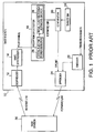
- the CDMA mobile communication system comprises a base station 10 and a mobile station 30.
- the base station 10 carries out a close loop control of reverse transmission power for the mobile station 30.
- the base station 10 includes a despreader 12, a RAKE synthesizer 14, a received SIR detector 16, a target SIR memory 18, a comparator 20, a encoder 22, and a spreader 24.
- the despreader 12 is connected to a transmitting/receiving section (not show) including an antenna and supplies a received signal from the transmitting/receiving section.
- the received signal includes a desired multi-path signal which includes an original reverse transmission signal transmitted from the mobile station 30 through an reverse link and a plurality of derivative transmission signals derived from the original reverse transmission signal.
- the received signal further includes an undesired signal which includes multi-pas signals supplied from other mobile stations (not shown).
- the original reverse transmission signal includes a reverse transmission data sequence as shown is Fig. 2A.
- the reverse transmission data sequence has a plurality of predetermined period each of which includes a pilot symbol period T PL .
- the reverse transmission data sequence comprises user's data and the pilot symbol periodically inserted in the user's data.
- the pilot symbol is automatically inserted in the user's data in a cycle of the predetermined period at the mobile station 30 to form the reverse transmission data sequence.
- the derivative transmission signals are generated by reflection of the original transmission signal by buildings or the like and reach the base station 10 via different paths.
- the despreader 12 despreads several of the original and derivative transmission signals by using a despreding code to produce path component signals having different delay times. For example, the despreader 12 despreads two or three of the original and the derivative transmission signals.
- the RAKE synthesizer 14 is connected to the despreader 12 and receives the path component signals supplied from the despreader 12.
- the RAKE synthesizer 14 demodulates the path component signals by using the pilot symbols included in the path component signals and carries out RAKE synthesis (or maximum ratio synthesis) to synthesize the demodulated path component signals in a predetermined time window and to produce a synthesized signal.
- the synthesized signal is a desired transmission data signal in the base station.
- the RAKE synthesizer 14 extracts a synthesized pilot symbol from each predetermined period of the synthesized signal and supplies it to the received SIR detector 16 in the predetermined period cycle.
- the received SIR detector 16 is connected to the RAKE synthesizer 14 and has a signal electric power detector 26 and a signal electric power averaging section 28.
- the signal electric power detector 26 detects or finds reception electric power of the desired transmission data signal by measuring strength of the synthesized pilot symbol whenever it receives the synthesized pilot symbol supplied from the RAKE synthesizer 14. Then, the signal electric power detector 26 produces an electric power value signal representative of the reception electric power of the desired transmission data signal in the predetermined period cycle.
- the signal electric power averaging section 28 calculates or measures an average of the reception electric power of the desired transmission data signal during it receives the electric power value signal. This means that the signal electric power averaging section 28 measures an average of the strength of the pilot symbol per pilot symbol period T PL or in the cycle of the predetermined period. Then the signal electric power averaging section 28 estimates an estimated signal-to-interference ratio (SIR) on the basis of the average of the reception electric power of the desired transmission data signal in the cycle of the predetermined period. The estimated SIR represents an estimated ratio of the reception electric power of the desired transmission data signal to reception electric power of the undesired signal. Thus, the signal electric power averaging section 28 supplies the estimated SIR to the comparator 20 in the predetermined period cycle.
- SIR signal-to-interference ratio
- the target SIR memory 18 memorizes a target SIR decided at a side of the CDMA mobile communication system.
- the comparator 20 is connected to the received SIT detector 16 and the target SIR memory 18.
- the comparator 20 compares the estimated SIR with the target SIR memorized in the target SIR memory 18 whenever it receives the estimated SIR from the signal electric power averaging section 28.
- the comparator 20 periodically produces a transmit power control bit (TPC bit) in the cycle of the predetermine period.
- the TPC bit is used for increasing the transmission power of the mobile station when the estimated SIR is larger than the target SIR while it is used for decreasing the transmission power of the mobile station when the estimated SIR is smaller than the target SIR.
- the encoder 22 encodes a transmission data for transmitting to the mobile station 30 and produces an encoded data.
- the spreader 24 is connected to the comparator 20, the encoder 22, and the transmitting/receiving section.
- the spreader 24 forms a forward transmission data sequence in which the TPC bit. is located in the cycle of the predetermined period as shown in Fig. 2B.
- the predetermined period is used as a transmission power control period T TPC .
- the spreader 24 spreads the forward transmission data sequence by using a spreading code for the mobile station 30.
- the transmitting/receiving section transmits a forward transmission data sequence as a forward transmission signal for the mobile station 30 through a forward link.
- the mobile station 30 receives the forward transmission signal and adjusting the transmission power according to the TPC bit included in each of the predetermined period of the forward transmission signal.
- the base station 10 finds the estimated SIR for the pilot symbol period T PL in each of transmission power control period T TPC to control the transmission power of the mobile station 30.
- the base station 10 does not carry out the closed loop control of transmitting power for the mobile station 30, the reception electric power of the desired transmission data signal is remarkably changed by fading as shown in Fig. 3A.
- the base station 10 carries out the closed loop control for the mobile station 30, the reception electric power of the desired signal converges a specific value decided by the target SIR as shown in Fig. 3B.
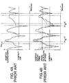
- the conventional CDMA transmission power control system has a problem that it can not prevent rapid fading, such as shown in Fig. 4A, though it can prevent slow fading shown in Figs. 3A and 3B. That is, the conventional CDMA transmission power control system enlarges change of the reception electric power of the desired transmission data signal when the fading includes instantaneous change of the reception electric power of the desired transmission data signal within the transmission power control period T TPC as shown in Fig. 4B.
- the reception electric power of the desired transmission data signal is increased during the period of T A of Fig. 4B by the closed loop control of the transmission power. This means that undesired signal for the other mobile stations increases.
- the reception electric power of the desired signal is reduced under a sensitivity limit during the period of T B of Fig. 4B by the closed loop control. This means that receiving sensitivity of the base station 10 deteriorates.
- the CDMA mobile communication system comprises a Doppler frequency detector 50 which is connected to the RAKE synthesizer 14 and the signal electric power averaging section 28.
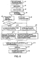
- the CDMA mobile communication system operates as illustrated in Fig. 6. Steps sl-s4, s6, and s8-s12 nearly corresponds to the operation of the conventional CDMA mobile communication system.
- the Doppler frequency detector 50 receives the synthesized pilot symbol from the RAKE synthesizer in the predetermined period cycle. In other words, the Doppler frequency detector 50 receives the synthesized pilot symbol per transmission control period T TPC .
- the Doppler frequency detector 50 finds a maximum Doppler frequency f D of the desired transmission data signal on the basis of the synthesized pilot symbol in each transmission power control period T TPC .
- the Doppler frequency detector 50 compares the maximum Doppler frequency f D with a Doppler frequency threshold f TH whenever it receives the synthesized pilot symbol.
- the Doppler frequency threshold f TH depends on the transmission power control period T TPC .
- the Doppler frequency threshold f TH is equal to 1/(8 ⁇ T TPC ). Though a proportional constant is equal to 1/8 in this case, it may be appropriately selected.
- the Doppler frequency detector 50 produces a result bit of "0". In this case, the step s7 goes to the step s8.
- the Doppler frequency detector 50 produces a result bit of "1". In this case the step s7 goes to both steps s13 and s14.
- a changing point is shown on a graph of the reception electric power of the desired transmission data signal between almost every transmission power control period T TPC as shown in Fig. 7A (or Fig 4A) .
- the changing point is an extremum (i.e. a maximum or a minimum) or an inflection point and brought by rapid fading or the like.
- carrying out the conventional closed loop control deteriorates the receiving characteristic of the base station 10 (refer to Fig. 4B).
- the Doppler frequency detector 50 substantially produces the result bit of "0" when the conventional closed loop control can suppress the fading.
- the Doppler frequency detector 50 substantially produces the result bit of "1".
- the Doppler frequency detector 50 produces the result bit "0" or "1" per the transmission power control period T TPC .
- the signal electric power averaging section 28 is different from that of Fig. 1 in operation.
- the signal electric power averaging section 28 carries out a different or an abnormal operation when it receives the result bit of "1" from the Doppler frequency detector 50.
- the signal electric power averaging section 28 receives the result bit of "0" from the Doppler frequency detector 50, it performs a normal operation like that of Fig. 1 in the step s8.
- the operation of the signal electric power averaging section 28 will be mentioned below in more detail.
- the signal electric power averaging section 28 When the signal electric power averaging section 28 receives the result bit of "0", it measures an average of the reception electric power of the desired signal between the pilot symbol period T PL in response to the electric power value signal supplied from the signal electric power detector 26.
- the signal electric power averaging section 28 when the signal electric power averaging section 28 receives the result bit of "1" , it performs the step s13. That is, the signal electric power averaging section 28 measures an average of the reception electric power of the desired transmission signal between N times the pilot symbol period T PL in response to the electric power value signals supplied N times from the signal electric power detector 26. "N" is an integer and considerably larger than 1. For example, "N” is 10.
- the signal electric power averaging section 28 produces the estimated SIR on the basis of the average of the reception electric power of the desired transmission signal. That is, the signal electric power averaging section 28 produces the estimated SIR per N times the transmission power control period T TPC .
- the signal electric power averaging section 28 measures the average of the reception electric power of the desired transmission signal for a long time. Therefore, the estimated SIR has practically no influence of instantaneous change of the reception electric power.
- the comparator 20 compares the estimated SIR with the target SIR memorized in the target SIR memory 18 whenever it receives the estimated SIR from the signal electric power averaging section 28. Then the comparator 20 produces TPC bits of "11” or "00" on the basis of the comparison result. The TPC bits of "11” is used for increasing the transmission power of the mobile station 30 while the TFC bits of "00" is used for reducing the transmission power of the mobile station 30. In addition, the comparator 20 performs the step s14 when the maximum Doppler frequency f D is not smaller than the Doppler frequency f TH .
- the comparator 20 produces the TPC bits of "10" or "01” (N-1) times correspondence to (N-1) times the pilot symbol period T PL while the estimated SIR is not supplied from the signal electric power averaging section in the step s14.
- the TPC bits of "10” or "01 " is used for maintaining the transmission power of the mobile station 30. This is because the TPC bits must be inserted in each transmission power control period T TPC of the forward transmission data sequence (refer to Fig. 2B) in the step s10.
- the comparator 20 produces one set of the TPC bits for changing the transmission power and (N-1) sets of the TPC bits for maintaining the transmission power per N times the transmission power control period T TPC when the maximum Doppler frequency f D is not smaller than the Doppler frequency f TH .
- the closed loop control is carried out in a cycle of N times the transmission power control period T TPC in appearance when the maximum Doppler frequency f D is not smaller than the Doppler frequency f TH .
- Fig. 8 shows relation between the maximum Doppler frequency with the apparent transmission power control period.
- the CDMA mobile communication system changes the apparent transmission power control period according to the maximum Doppler frequency. Accordingly, the CDMA mobile communication system can prevent deteriorating of the receiving characteristic of the base station and increasing of the interference power for the other mobile stations.
- fading includes both of rapid fading component and slow fading component as shown in Fig. 7B.
- the slow fading component depends on density, heights and positions of buildings, undulations, and an interval between a mobile station and a base station.
- the CDMA mobile communication system of Fig. 5 can suppress the slow fading component by extending the apparent transmission power control period into from several milliseconds to several seconds or dozens seconds as shown in Fig. 7C. That is, the reception electric power converges the specific value depending the target SIR.
- the Doppler frequency detector 50 produces the result bit "1" when the maximum Doppler frequency F D is equal to the Doppler frequency threshold F TH , it may produces the result bit "0".
Landscapes
- Engineering & Computer Science (AREA)
- Computer Networks & Wireless Communication (AREA)
- Signal Processing (AREA)
- Mobile Radio Communication Systems (AREA)
- Transmitters (AREA)
- Transceivers (AREA)
Abstract
Description
Claims (10)
- A CDMA transmission power control method for controlling reverse transmission power, characterized by the steps of:judging whether fading of a reverse transmission data signal includes rapid change component or not by using a pilot symbol inserted in the reverse transmission data signal;normal adjusting the reverse transmission power per transmission power control period of the reverse transmission data signal while the fading does not have the rapid change component; andabnormal adjusting the reverse transmission power per N (N: integer larger than 1) times the transmission power control period while the fading has the rapid change component.
- A CDMA transmission power control method as claimed in Claim 1, characterized in that the judging step comprises the steps of:finding a maximum Doppler frequency within each transmission power control period of the reverse transmission data signal by using the pilot symbol; andcomparing the maximum Doppler frequency with a frequency threshold to judge whether the fading includes the rapid change component or not.
- A CDMA transmission power control method as claimed in Claim 1 or 2, characterized in that the abnormal adjusting step repeats two steps of:maintaining the reverse transmission power for N-1 times the transmission power control period; andadjusting the reverse transmission power in the transmission power control period.
- A CDMA transmission power control method as claimed in any of Claims 1 to 3, characterized by further comprising the steps of:normal measuring an average strength of the pilot symbol per transmission power control period while the fading does not has the rapid change component;abnormal measuring an averaging strength of the pilot symbol per N times transmission power control period while the fading has the rapid change component;estimating a signal to interfering ratio on the basis of the average strength of the pilot symbol; andcomparing the signal to interfering ratio with a target to carry out the normal and the abnormal adjusting steps.
- A CDMA transmission power control method for controlling reverse transmission power in a CDMA mobile communication system including a base station and a mobile station, characterized by the steps of:receiving, in said base station, a reverse transmission data signal transmitted from said mobile station, the reverse transmission data signal has a pilot symbol inserted in the reverse transmission data signal per transmission power control period;extracting, in said base station, the pilot symbol from the reverse transmission data signal per transmission power control period;finding, in said base station, a maximum Doppler frequency by using the pilot symbol per transmission power control period;comparing, in said base station, the maximum Doppler frequency with a threshold frequency;expanding, in said base station, an apparent transmission power control period into N (N: integer larger than 1) times the transmission power control period when the maximum Doppler frequency is larger than the threshold frequency.
- A CDMA transmission power control method as claimed in Claim 5, characterized in that the expanding step comprises the step of:
maintaining the transmission power for N-1 times the transmission power control period in the apparent transmission control period. - A CDMA transmission power control method as claimed in Claim 5 or 6, characterized by further comprising the steps of:normal measuring an average strength of the pilot symbol per transmission power control period when the maximum Doppler frequency is smaller than the threshold frequency;abnormal measuring an average strength of the pilot symbol per N times the transmission power control period when the maximum Doppler frequency is larger than the threshold frequency; andadjusting the transmission power according to the average strength of the pilot symbol.
- A CDMA transmission power control system for controlling reverse transmission power, characterized by comprising:a Doppler frequency detector detecting a maximum Doppler frequency of a reverse transmission data signal per transmission power control period; anda transmission power control bit producing unit connected to the Doppler frequency detector for producing transmission power control bits in a variable cycle depending on the Doppler frequency.
- A CDMA transmission power control system as claimed in Claim 8, characterized by further comprising:
a RAKE synthesizer for extracting a pilot symbol from the reverse transmission data signal per transmission power control period to supply the pilot symbol to said Doppler frequency detector, wherein said Doppler frequency detector detects the maximum Doppler frequency by using the pilot symbol. - A CDMA transmission power control system as claimed in Claim 8 or 9, characterized in that said transmission power control bit producing unit comprises:wherein said comparator produces an additional transmission power control bits per transmission power control period to maintain the reverse transmission power when the estimated signal to interfering ratio is not supplied from said signal electric power averaging section and when the maximum Doppler frequency is larger than the frequency threshold.a signal electric power averaging section connected to said Doppler frequency detector for producing an estimated signal to interfering ratio per transmission power control period when the maximum Doppler frequency is smaller than a frequency threshold and per N times transmission power control period when the maximum Doppler frequency is larger than the frequency threshold;a memory memorizing a target signal to interfering ratio; anda comparator connected to said signal electric power averaging section and said memory for comparing said estimated signal to interfering ratio with the target signal to interfering ratio to produce transmission power control bits,
Applications Claiming Priority (2)
| Application Number | Priority Date | Filing Date | Title |
|---|---|---|---|
| JP34254499 | 1999-12-01 | ||
| JP34254499A JP2001160776A (en) | 1999-12-01 | 1999-12-01 | Method for setting transmission power control period, transmission power control period setting device and transmission power control period setting system |
Publications (2)
| Publication Number | Publication Date |
|---|---|
| EP1107473A2 true EP1107473A2 (en) | 2001-06-13 |
| EP1107473A3 EP1107473A3 (en) | 2003-06-18 |
Family
ID=18354580
Family Applications (1)
| Application Number | Title | Priority Date | Filing Date |
|---|---|---|---|
| EP20000125357 Withdrawn EP1107473A3 (en) | 1999-12-01 | 2000-11-30 | Variable CDMA transmission power control cycle |
Country Status (6)
| Country | Link |
|---|---|
| US (1) | US20010002905A1 (en) |
| EP (1) | EP1107473A3 (en) |
| JP (1) | JP2001160776A (en) |
| KR (1) | KR100371294B1 (en) |
| CN (1) | CN1305279A (en) |
| BR (1) | BR0005992A (en) |
Cited By (2)
| Publication number | Priority date | Publication date | Assignee | Title |
|---|---|---|---|---|
| GB2394871A (en) * | 2002-11-01 | 2004-05-05 | Kddi Corp | Transmitter which selects between OFDM and MC-CDMA |
| EP1775852A3 (en) * | 2005-10-14 | 2008-03-12 | M/A-Com, Inc. | Methods and apparatuses for transmission power control in a wireless communication system according to fading |
Families Citing this family (10)
| Publication number | Priority date | Publication date | Assignee | Title |
|---|---|---|---|---|
| JP2001218253A (en) * | 2000-02-02 | 2001-08-10 | Nec Saitama Ltd | Wireless communication system |
| JP3583388B2 (en) * | 2001-06-29 | 2004-11-04 | 松下電器産業株式会社 | Data communication device and data communication method |
| JP3676991B2 (en) * | 2001-07-05 | 2005-07-27 | 松下電器産業株式会社 | Wireless communication apparatus and wireless communication method |
| JP3649179B2 (en) * | 2001-12-04 | 2005-05-18 | 住友電気工業株式会社 | Mobile communication device |
| KR100830495B1 (en) * | 2001-12-29 | 2008-05-21 | 엘지전자 주식회사 | Doppler transition estimation method and data transmission method using the same |
| WO2003100992A2 (en) * | 2002-05-09 | 2003-12-04 | Nokia Corporation | Multiple level power control command signaling |
| KR20040024945A (en) * | 2002-09-18 | 2004-03-24 | 강법주 | Closed-Loop-Power-Control Method Using Doppler Frequency Estimation in CDMA System |
| US7072680B2 (en) * | 2003-05-28 | 2006-07-04 | Accton Technology Corporation | Power control apparatus for achieving respective desired signal quality levels in wireless communication systems and method |
| JP4665469B2 (en) * | 2004-09-15 | 2011-04-06 | 日本電気株式会社 | Mobile communication terminal device and transmission power control method |
| KR20090004773A (en) * | 2007-07-06 | 2009-01-12 | 엘지전자 주식회사 | Digital broadcasting system and data processing method |
Family Cites Families (3)
| Publication number | Priority date | Publication date | Assignee | Title |
|---|---|---|---|---|
| KR0162978B1 (en) * | 1996-02-06 | 1998-12-01 | 서정욱 | Apparatus and method for measuring signal-to-interference ratio for received signal in code division multiple access system |
| JPH1079701A (en) * | 1996-09-03 | 1998-03-24 | Fujitsu Ltd | Mobile communication terminal and transmission power control method thereof |
| JP3805520B2 (en) * | 1998-01-28 | 2006-08-02 | 富士通株式会社 | Speed estimation apparatus and method in mobile communication |
-
1999
- 1999-12-01 JP JP34254499A patent/JP2001160776A/en active Pending
-
2000
- 2000-11-30 EP EP20000125357 patent/EP1107473A3/en not_active Withdrawn
- 2000-11-30 KR KR10-2000-0071848A patent/KR100371294B1/en not_active Expired - Fee Related
- 2000-11-30 US US09/725,678 patent/US20010002905A1/en not_active Abandoned
- 2000-12-01 BR BR0005992A patent/BR0005992A/en not_active IP Right Cessation
- 2000-12-01 CN CN00133667A patent/CN1305279A/en active Pending
Cited By (3)
| Publication number | Priority date | Publication date | Assignee | Title |
|---|---|---|---|---|
| GB2394871A (en) * | 2002-11-01 | 2004-05-05 | Kddi Corp | Transmitter which selects between OFDM and MC-CDMA |
| US7391715B2 (en) | 2002-11-01 | 2008-06-24 | Kddi Corporation | Transmitter device and transmitting method using OFDM and MC-CDMA |
| EP1775852A3 (en) * | 2005-10-14 | 2008-03-12 | M/A-Com, Inc. | Methods and apparatuses for transmission power control in a wireless communication system according to fading |
Also Published As
| Publication number | Publication date |
|---|---|
| JP2001160776A (en) | 2001-06-12 |
| CN1305279A (en) | 2001-07-25 |
| KR20010062006A (en) | 2001-07-07 |
| EP1107473A3 (en) | 2003-06-18 |
| BR0005992A (en) | 2001-07-24 |
| KR100371294B1 (en) | 2003-02-07 |
| US20010002905A1 (en) | 2001-06-07 |
Similar Documents
| Publication | Publication Date | Title |
|---|---|---|
| US7366538B2 (en) | Mobile communication system and communication method for mobile communication system | |
| US7532888B2 (en) | CDMA mobile communication system, base station, mobile station and communication control method during soft handover | |
| US7266096B2 (en) | Radio infrastructure apparatus | |
| Ariyavisitakul | Signal and interference statistics of a CDMA system with feedback power control. II | |
| JP3543959B2 (en) | base station | |
| US6490461B1 (en) | Power control based on combined quality estimates | |
| EP0823793B1 (en) | Mobile communication system and apparatus with transmission power control | |
| EP1013113B1 (en) | Forward link power control device and methods for a mobile communication system supporting transmission diversity | |
| US6804531B2 (en) | Closed loop power control with adjustable width based on channel quality | |
| US6173187B1 (en) | Method of setting load goal, and radio system | |
| CA2260062A1 (en) | Power presetting in a radio communication system | |
| EP1068677A1 (en) | Downlink power control in a cellular mobile radio communications system | |
| US20040202113A1 (en) | Transmission controller, wireless base station, and method of controlling transmission rate | |
| EP1107473A2 (en) | Variable CDMA transmission power control cycle | |
| EP1401120B1 (en) | Base station for mobile communication system | |
| KR20000071302A (en) | Open loop power control for wireless mobile stations | |
| AU2522900A (en) | A method for improving performances of a mobile radio communication system using a power control algorithm | |
| US7058028B1 (en) | Method for controlling the transmission power | |
| EP1895682A1 (en) | Transmission power control method and apparatus | |
| EP1221209A1 (en) | Radio transceiver with velocity dependent signal quality estimation | |
| GB2382278A (en) | Method of determining electric field state of a mobile station in view of electric field state of uplink | |
| EP1032140A2 (en) | Base station apparatus, mobile station apparatus and radio communication method for transmission power control | |
| US7123597B1 (en) | Transmit power control method in CDMA mobile communication system | |
| US20020160797A1 (en) | Base station apparatus and transmission power control method |
Legal Events
| Date | Code | Title | Description |
|---|---|---|---|
| PUAI | Public reference made under article 153(3) epc to a published international application that has entered the european phase |
Free format text: ORIGINAL CODE: 0009012 |
|
| AK | Designated contracting states |
Kind code of ref document: A2 Designated state(s): AT BE CH CY DE DK ES FI FR GB GR IE IT LI LU MC NL PT SE TR |
|
| AX | Request for extension of the european patent |
Free format text: AL;LT;LV;MK;RO;SI |
|
| PUAL | Search report despatched |
Free format text: ORIGINAL CODE: 0009013 |
|
| AK | Designated contracting states |
Designated state(s): AT BE CH CY DE DK ES FI FR GB GR IE IT LI LU MC NL PT SE TR |
|
| AX | Request for extension of the european patent |
Extension state: AL LT LV MK RO SI |
|
| 17P | Request for examination filed |
Effective date: 20030512 |
|
| 17Q | First examination report despatched |
Effective date: 20030730 |
|
| AKX | Designation fees paid |
Designated state(s): DE GB |
|
| STAA | Information on the status of an ep patent application or granted ep patent |
Free format text: STATUS: THE APPLICATION IS DEEMED TO BE WITHDRAWN |
|
| 18D | Application deemed to be withdrawn |
Effective date: 20031210 |