EP1107470A2 - Method for synchronizing a receiver in a positioning system - Google Patents
Method for synchronizing a receiver in a positioning system Download PDFInfo
- Publication number
- EP1107470A2 EP1107470A2 EP00660223A EP00660223A EP1107470A2 EP 1107470 A2 EP1107470 A2 EP 1107470A2 EP 00660223 A EP00660223 A EP 00660223A EP 00660223 A EP00660223 A EP 00660223A EP 1107470 A2 EP1107470 A2 EP 1107470A2
- Authority
- EP
- European Patent Office
- Prior art keywords
- code
- receiver
- basis
- hartley transform
- forming
- Prior art date
- Legal status (The legal status is an assumption and is not a legal conclusion. Google has not performed a legal analysis and makes no representation as to the accuracy of the status listed.)
- Withdrawn
Links
Images



Classifications
-
- H—ELECTRICITY
- H04—ELECTRIC COMMUNICATION TECHNIQUE
- H04B—TRANSMISSION
- H04B1/00—Details of transmission systems, not covered by a single one of groups H04B3/00 - H04B13/00; Details of transmission systems not characterised by the medium used for transmission
- H04B1/69—Spread spectrum techniques
- H04B1/707—Spread spectrum techniques using direct sequence modulation
- H04B1/7073—Synchronisation aspects
- H04B1/7075—Synchronisation aspects with code phase acquisition
- H04B1/70751—Synchronisation aspects with code phase acquisition using partial detection
- H04B1/70752—Partial correlation
-
- G—PHYSICS
- G01—MEASURING; TESTING
- G01S—RADIO DIRECTION-FINDING; RADIO NAVIGATION; DETERMINING DISTANCE OR VELOCITY BY USE OF RADIO WAVES; LOCATING OR PRESENCE-DETECTING BY USE OF THE REFLECTION OR RERADIATION OF RADIO WAVES; ANALOGOUS ARRANGEMENTS USING OTHER WAVES
- G01S19/00—Satellite radio beacon positioning systems; Determining position, velocity or attitude using signals transmitted by such systems
- G01S19/01—Satellite radio beacon positioning systems transmitting time-stamped messages, e.g. GPS [Global Positioning System], GLONASS [Global Orbiting Navigation Satellite System] or GALILEO
- G01S19/03—Cooperating elements; Interaction or communication between different cooperating elements or between cooperating elements and receivers
- G01S19/09—Cooperating elements; Interaction or communication between different cooperating elements or between cooperating elements and receivers providing processing capability normally carried out by the receiver
-
- G—PHYSICS
- G01—MEASURING; TESTING
- G01S—RADIO DIRECTION-FINDING; RADIO NAVIGATION; DETERMINING DISTANCE OR VELOCITY BY USE OF RADIO WAVES; LOCATING OR PRESENCE-DETECTING BY USE OF THE REFLECTION OR RERADIATION OF RADIO WAVES; ANALOGOUS ARRANGEMENTS USING OTHER WAVES
- G01S19/00—Satellite radio beacon positioning systems; Determining position, velocity or attitude using signals transmitted by such systems
- G01S19/01—Satellite radio beacon positioning systems transmitting time-stamped messages, e.g. GPS [Global Positioning System], GLONASS [Global Orbiting Navigation Satellite System] or GALILEO
- G01S19/13—Receivers
- G01S19/24—Acquisition or tracking or demodulation of signals transmitted by the system
-
- G—PHYSICS
- G01—MEASURING; TESTING
- G01S—RADIO DIRECTION-FINDING; RADIO NAVIGATION; DETERMINING DISTANCE OR VELOCITY BY USE OF RADIO WAVES; LOCATING OR PRESENCE-DETECTING BY USE OF THE REFLECTION OR RERADIATION OF RADIO WAVES; ANALOGOUS ARRANGEMENTS USING OTHER WAVES
- G01S19/00—Satellite radio beacon positioning systems; Determining position, velocity or attitude using signals transmitted by such systems
- G01S19/01—Satellite radio beacon positioning systems transmitting time-stamped messages, e.g. GPS [Global Positioning System], GLONASS [Global Orbiting Navigation Satellite System] or GALILEO
- G01S19/13—Receivers
- G01S19/24—Acquisition or tracking or demodulation of signals transmitted by the system
- G01S19/29—Acquisition or tracking or demodulation of signals transmitted by the system carrier including Doppler, related
-
- G—PHYSICS
- G01—MEASURING; TESTING
- G01S—RADIO DIRECTION-FINDING; RADIO NAVIGATION; DETERMINING DISTANCE OR VELOCITY BY USE OF RADIO WAVES; LOCATING OR PRESENCE-DETECTING BY USE OF THE REFLECTION OR RERADIATION OF RADIO WAVES; ANALOGOUS ARRANGEMENTS USING OTHER WAVES
- G01S19/00—Satellite radio beacon positioning systems; Determining position, velocity or attitude using signals transmitted by such systems
- G01S19/01—Satellite radio beacon positioning systems transmitting time-stamped messages, e.g. GPS [Global Positioning System], GLONASS [Global Orbiting Navigation Satellite System] or GALILEO
- G01S19/13—Receivers
- G01S19/24—Acquisition or tracking or demodulation of signals transmitted by the system
- G01S19/30—Acquisition or tracking or demodulation of signals transmitted by the system code related
-
- H—ELECTRICITY
- H04—ELECTRIC COMMUNICATION TECHNIQUE
- H04B—TRANSMISSION
- H04B1/00—Details of transmission systems, not covered by a single one of groups H04B3/00 - H04B13/00; Details of transmission systems not characterised by the medium used for transmission
- H04B1/69—Spread spectrum techniques
- H04B1/707—Spread spectrum techniques using direct sequence modulation
- H04B1/7073—Synchronisation aspects
- H04B1/7075—Synchronisation aspects with code phase acquisition
- H04B1/7077—Multi-step acquisition, e.g. multi-dwell, coarse-fine or validation
-
- H—ELECTRICITY
- H04—ELECTRIC COMMUNICATION TECHNIQUE
- H04L—TRANSMISSION OF DIGITAL INFORMATION, e.g. TELEGRAPHIC COMMUNICATION
- H04L27/00—Modulated-carrier systems
- H04L27/0014—Carrier regulation
-
- G—PHYSICS
- G01—MEASURING; TESTING
- G01S—RADIO DIRECTION-FINDING; RADIO NAVIGATION; DETERMINING DISTANCE OR VELOCITY BY USE OF RADIO WAVES; LOCATING OR PRESENCE-DETECTING BY USE OF THE REFLECTION OR RERADIATION OF RADIO WAVES; ANALOGOUS ARRANGEMENTS USING OTHER WAVES
- G01S2205/00—Position-fixing by co-ordinating two or more direction or position line determinations; Position-fixing by co-ordinating two or more distance determinations
- G01S2205/001—Transmission of position information to remote stations
- G01S2205/008—Transmission of position information to remote stations using a mobile telephone network
-
- H—ELECTRICITY
- H04—ELECTRIC COMMUNICATION TECHNIQUE
- H04B—TRANSMISSION
- H04B1/00—Details of transmission systems, not covered by a single one of groups H04B3/00 - H04B13/00; Details of transmission systems not characterised by the medium used for transmission
- H04B1/69—Spread spectrum techniques
- H04B1/707—Spread spectrum techniques using direct sequence modulation
- H04B1/7097—Interference-related aspects
- H04B1/7103—Interference-related aspects the interference being multiple access interference
- H04B1/7105—Joint detection techniques, e.g. linear detectors
- H04B1/71052—Joint detection techniques, e.g. linear detectors using decorrelation matrix
-
- H—ELECTRICITY
- H04—ELECTRIC COMMUNICATION TECHNIQUE
- H04B—TRANSMISSION
- H04B2201/00—Indexing scheme relating to details of transmission systems not covered by a single group of H04B3/00 - H04B13/00
- H04B2201/69—Orthogonal indexing scheme relating to spread spectrum techniques in general
- H04B2201/707—Orthogonal indexing scheme relating to spread spectrum techniques in general relating to direct sequence modulation
- H04B2201/70715—Orthogonal indexing scheme relating to spread spectrum techniques in general relating to direct sequence modulation with application-specific features
-
- H—ELECTRICITY
- H04—ELECTRIC COMMUNICATION TECHNIQUE
- H04L—TRANSMISSION OF DIGITAL INFORMATION, e.g. TELEGRAPHIC COMMUNICATION
- H04L27/00—Modulated-carrier systems
- H04L27/0014—Carrier regulation
- H04L2027/0044—Control loops for carrier regulation
- H04L2027/0053—Closed loops
- H04L2027/0057—Closed loops quadrature phase
-
- H—ELECTRICITY
- H04—ELECTRIC COMMUNICATION TECHNIQUE
- H04L—TRANSMISSION OF DIGITAL INFORMATION, e.g. TELEGRAPHIC COMMUNICATION
- H04L27/00—Modulated-carrier systems
- H04L27/0014—Carrier regulation
- H04L2027/0044—Control loops for carrier regulation
- H04L2027/0063—Elements of loops
- H04L2027/0065—Frequency error detectors
-
- H—ELECTRICITY
- H04—ELECTRIC COMMUNICATION TECHNIQUE
- H04L—TRANSMISSION OF DIGITAL INFORMATION, e.g. TELEGRAPHIC COMMUNICATION
- H04L27/00—Modulated-carrier systems
- H04L27/0014—Carrier regulation
- H04L2027/0044—Control loops for carrier regulation
- H04L2027/0071—Control of loops
- H04L2027/0075—Error weighting
- H04L2027/0077—Error weighting stop and go
Definitions
- the present invention relates to a method according to the preamble of Claim 1 for performing the synchronization operations of a receiver, a positioning system according to the preamble of Claim 9, a receiver according to the preamble of Claim 14, an electronic device according to the preamble of Claim 22, and an electronic device according to the preamble of Claim 29.
- a well-known positioning system is the Global Positioning System, GPS, which now comprises over 20 satellites, 4 of which or more are simultaneously visible to a receiver.
- GPS Global Positioning System
- These satellites transmit, for instance, Ephemeris data and data of the satellite time.
- the receiver used in positioning determines its location by calculating the transit time to the receiver of a signal transmitted simultaneously from several satellites of the positioning system. For determining its location, the receiver must typically receive the signal of at least four visible satellites to be able to calculate the location.
- the satellites transmit an L2 signal at the carrier frequency of 1227.6 MHz, or 120f 0 .
- these signals are modulated with at least one pseudo-random sequence. Each satellite has a different pseudo-random sequence.
- the signal is a code modulated wideband signal.
- the modulation technique used makes it possible for the receiver to distinguish between signals transmitted by different satellites, although the carrier frequencies used in the transmission are essentially the same. This modulation technique is called Code Division Multiple Access (CDMA).
- CDMA Code Division Multiple Access
- the pseudo-random sequence used in each satellite for the modulation of the L1 signal is, for instance, a so-called C/A code (Coarse/Acquisition code), an example of which is the Gold code.
- C/A code Coarse/Acquisition code
- Each GPS satellite transmits a signal by using a unique C/A code.
- the codes are formed as the modulo 2 sum of two 1023-bit binary sequences.
- the first binary sequence G1 has been formed with the polynome X 10 +X 3 +1
- the second binary sequence G2 has been formed by delaying the polynome X 10 +X 9 +X 8 +X 6 +X 3 +X 2 +1 so that each satellite has a different delay. This arrangement enables generating different C/A codes with a similar code generator.
- the C/A codes are binary codes, the chipping rate of which in the GPS system is 1.023 MHz.
- the C/A code comprises 1023 chips, whereby the repeating time of the code, epoch, is 1 ms.
- the carrier wave of the L1 signal is further modulated with navigation information at a bit rate of 50 bit/s.
- the navigation information comprises information about the "health", orbit and time of the satellite, for instance.
- the satellites monitor the condition of their equipment during operation.
- the satellites can use so-called watch-dog functions to detect errors in the equipment and notify about them Errors and malfunctions can be either momentary or long-term in nature.
- Errors and malfunctions can be either momentary or long-term in nature.
- some of the errors can be possibly compensated for, or the information transmitted by a malfunctioning satellite can be entirely ignored.
- the information received from different satellites can be emphasized in different ways on the basis of the health information. Thus it is possible to minimize errors that satellites which seem to be unreliable may cause in the measurements.
- the receiver In order to detect the signals of the satellites and to identify the satellites, the receiver must perform synchronization, whereby the receiver seeks out the signal of each satellite each time and tries to synchronize with this signal so that the data transmitted with the signal can be received and demodulated.
- a location determination receiver must carry out synchronization when, for instance, the receiver is switched on, and also in a situation where the receiver has not been able to receive the signal of any satellite for a long time.
- a situation like this can arise easily, because the device is moving, and the antenna of the device is not always in an optimal position in relation to the satellites, which weakens the strength of the signal coming to the receiver.
- buildings have a blocking effect on the received signal, and in addition, the signal can proceed to the receiver along several different routes, such as straight from the satellite (line-of-sight) and as reflected from buildings. As a result of this multipath propagation, the same signal is received as several signals in different phases.
- the positioning arrangement has two main functions:
- the distances to the satellites are called pseudoranges, because the time is not known accurately in the receiver. Because the time is not known with an absolute accuracy, the location and time must be determined preferably by iterating the measured data with a linearized equation group. Then the determination of the location and time is repeated, until a sufficient accuracy of time and location has been achieved.
- the calculation of the pseudorange can be carried out by measuring the mutual, apparent transit time delays of the signals of different satellites. After the receiver has become synchronized with the received signal, the information transmitted in the signal is detected.
- GPS navigation receivers use correlation methods for carrying out synchronization functions, i.e. code acquisition and/or maintaining synchronization (tracking).
- the reference codes r(x) or pseudo random sequences of different satellites have been saved or are generated locally in the location determination receiver.
- a down conversion is performed on the received signal, whereafter the receiver multiplies the received signal with the saved pseudo random sequence.
- the signal formed as the result of the multiplication is integrated or low-pass filtered, whereby the result tells if the received signal contained a signal transmitted by the satellite.
- the multiplication carried out in the receiver is repeated so that each time the phase of the pseudo random sequence saved in the receiver is shifted.
- the right phase is concluded from the correlation result preferably so that when the correlation result is the highest, the right phase has been found. Then the receiver is correctly synchronized with the received signal.
- the frequency is adjusted and phase locking is carried out.
- This correlation result also expresses the information transmitted in the GPS signal.
- Some prior art GPS receivers use the FFT technique for determining the Doppler shift of the received GPS signal in connection with ordinary correlators. In these receivers, correlation is used to reduce the bandwidth of the received signal to 10 kHz-30 kHz. This narrow-band signal is analyzed with FFT algorithms to determine the carrier frequency.
- a GPS receiver and a method for processing GPS signals have been presented in the international patent application WO 97/14057.
- the receiver presented in this specification comprises two separate receivers, of which the first receiver is intended for use in a situation where the strength of the received signal is sufficient, and the second receiver is intended for use in a situation where the strength of the received signal is not sufficient for a sufficiently accurate location determination when the first receiver is used.
- the received signal is digitized and saved in memory media, whereby these saved signals are later processed in a digital signal processing unit.
- the digital signal processing unit performs convolution operations to the received, digitized signal. The purpose of these convolution operations is to calculate pseudoranges.
- the number of PM frames saved in the memory media is typically from one hundred to one thousand, which corresponds to a signal of the length of 100 ms to 1 s. After this, a saved code corresponding to the code of the satellite to be examined is retrieved from the memory of the receiver to be used for analyzing the received signal.
- the Doppler shift is also removed in the receiver.
- the amount of this Doppler shift has been determined either with the first receiver or on the basis of information received from a base station of the GPS system.
- a coherent summing of consecutive frames is performed.
- a fast Fourier transformation is performed on the data set received as the result of this summing.
- a multiplication is performed on the Fourier transformation result, using the complex conjugate of the Fourier transformation of the reference signal saved in the memory media as one multiplier.
- An inverse Fourier transformation is further performed on the result of this multiplication, whereby a number of correlation results are received.
- correlation has been replaced by a Fourier transformation, whereby the number of calculations has been reduced. According to the specification, the method makes location determination 10 to 100 times faster as compared to the solutions known at the time of filing the specification.
- Matched filters are used in some prior art receivers for the locking and tracking of the signal.
- the use of matched filters entails the drawback that they consume a relatively high amount of power, which limits the use of matched filters especially in mobile devices.
- the invention is especially suitable for use in location determination receivers, but also in other receivers, preferably in CDMA receivers, in which the receiver must become synchronized with a spread spectrum signal.
- the invention is based on the idea that the time-to-frequency conversions and the inverse or frequency-to-time conversions are performed with a fast Hartley conversion and a corresponding inverse conversion. Thus the corresponding calculations can be performed faster than in the prior art solutions, such as systems based on FFT transformations.
- the method according to the present invention is characterized in what is set forth in the characterizing part of Claim 1.
- the positioning system according to the present invention is characterized in what is set forth in the characterizing part of Claim 9.
- the receiver according to the first preferred embodiment of the present invention is characterized in what is set forth in the characterizing part of Claim 14.
- the electronic device according to the present invention is characterized in what is set forth in the characterizing part of Claim 22.
- the electronic device according to the second preferred embodiment of the present invention is further characterized in what is set forth in the characterizing part of Claim 29.
- the present invention provides considerable advantages as compared to the prior art methods and receivers.
- the conversions can be performed faster and with lower power consumption as compared to, for example, FFT-based systems. Especially in location determination receivers, it is thus possible to make it faster for the receiver to become synchronized with the received signal.
- the real-time time-to-frequency and frequency-to-time conversion according to the invention can be implemented with a semiconductor circuit of a substantially smaller area than in the prior art solutions.
- the method according to the invention provides a substantial improvement of the synchronization speed as compared to the prior art methods.
- the total energy consumption of the receiver according to the invention can be kept reasonable, which makes the invention especially suitable for use in portable devices.
- the location determination receiver can also be implemented in connection with a mobile station.
- the Hartley transform can be presented with the formula: and the inverse Hartley transform can be presented with the formula: where
- N 2 calculations are needed to calculate a discrete Hartley transform.
- this number can be reduced by means of permutations known from the theory of mathematical conversions and the so-called Butterfly process, whereby the conversions can be carried out with Nlog 2 N calculations.
- This conversion is then called a fast Hartley transform, FHT.
- FHT fast Hartley transform
- the convolution equation is simplified to the form H 1 ( f ) ⁇ H 2 ( f ).
- the above described convolution can be utilized when calculating, for example, the correlation between two signals.
- either of the signals is turned to its mirror image in the time domain, and the convolution is preferably calculated by using the above described Hartley transforms. This will be described later in this specification.
- the received signal is preferably converted to an intermediate frequency in the converter block 2.
- the signal comprises two components, I and Q, between which there is a phase difference of 90°.
- These analog signal components, which are converted to the intermediate frequency are digitized in the digitizing block 3 and conducted to the multiplier block 4.
- the I and Q components of the digitized signal are multiplied with the signal generated by the Numerically Controlled Oscillator (NCO) 5.
- NCO Numerically Controlled Oscillator
- This signal of the numerically controlled oscillator 5 is intended to correct the frequency deviation caused by the Doppler shift and the frequency error of the local oscillator (not shown) of the receiver 1.
- the signal formed by the multiplier block 4 is led to the synchronization block 6, in which the method according to the invention is applied.
- This synchronization block 6 thus tries to establish the code phase and frequency deviation of the satellite, which are to be used in functions after the synchronization. This will be discussed later in this specification.
- the scanning block 8 is controlled with the control block 7 during synchronization, and the scanning block 8 is used to regulate the frequency of the numerically controlled oscillator 5 when required.
- the control block 7 controls the first switch 9 to switch either the signal formed by this scanning block 8 to the numerically controlled oscillator 5 during synchronization or the control signal formed by the code tracking block 11 to the numerically controlled oscillator 5 when synchronization has been achieved.
- a second switch 10 is used to control the operation of this tracking block 11.
- This tracking block 11 forms a part of a code phase locked loop and a carrier phase locked loop, which are known as such (not shown).
- a two-dimensional search step is preferably carried out in the receiver 1 for each satellite to which signal reception is targeted.
- the purpose is to determine the carrier frequency and code phase of each satellite.
- This carrier frequency is influenced by the Doppler shift caused by the movement of the satellite, the multipath propagation and the inaccuracies of the local oscillator of the receiver.
- the receiver 1 does not know the exact code phase, either, and hence the receiver must also determine the code phase from 1023 possible code phases. This results in a two-dimensional search process, in which one dimension is a frequency deviation in the band of 12 kHz, and the other dimension is a code phase out of 1023 different code phases.
- a method according to a preferred embodiment of the invention it is possible to examine a frequency band of approx. 500 Hz at a time, and hence the method is repeated 24 times when required, to cover the whole frequency band of 12 kHz to be examined.
- the values used in this specification only serve as examples which clarify the invention, but do not constitute a limitation thereof.
- the invention can also be applied in other than GPS systems, in which case the frequency values, code phases and the number of codes can vary.
- the scanning block 8 sets the frequency of the numerically controlled oscillator 5 such that the receiver 1 advantageously receives the lowest frequencies of the frequency band, 1575.414MHz-1575.4145 MHz in this example.
- the receiver can also specify the starting frequency so that the receiver utilizes previously determined location information and/or almanac information, whereby the location determination can be made even faster.
- Samples of the received signal are saved in the sample vector formation block 12 preferably as complex sample vectors p(1), p(2)...p(N), each of which includes 1023 samples in this preferred embodiment.
- the sample saving frequency of the sample vector formation block 12 is essentially the same as the chipping rate of the chips, which is approx. 1 023 000 samples per second.
- the sample vectors are continuous so that the next sample vector continues temporally after the previous sample vector, or the time interval between the last sample of the sample vector and the first sample of the next sample vector is essentially the same as the time interval between consecutive samples of the sample vector.
- These 1023 samples thus correspond to a signal of 1 ms, and hence in a time-to-frequency transformation the frequency band is 1 kHz, which can be partly utilized.
- the sample vector formation step is denoted with the reference number 101 in Fig. 2 in this specification.
- the number of sample vectors is preferably N.
- the formation of sample vectors can be repeated.
- the value of the number N of sample vectors p(1), p(2)...p(N) is determined in the GPS system, it must be taken into consideration that information has been modulated on to the signal at a bit rate of 50 bits/s as binary phase modulation.
- Another factor, which limits this number N of the sample vectors p(1), p(2)...p(N) is the frequency stability of the local oscillator of the receiver.
- the synchronization method according to the invention also comprises a correlation step for forming a correlation function matrix.
- This correlation step can be partly performed already during sampling, or after N sample vectors p(1), p(2)...p(N) have been formed. If the correlation step is performed in such a manner, for instance, that a time-to-frequency transformation is calculated for each sample vector after it has been saved, preferably with a fast Hartley transform (FHT), the same time-to-frequency transformer can be used in all N sample vectors p(1), p(2)...p(N). But if the correlation step is performed after the saving of N sample vectors, a separate time-to-frequency transformer must be used for each sample vector, or the time-to-frequency transforms are performed for different sample vectors consecutively in the same time-to-frequency transformer.
- FHT fast Hartley transform
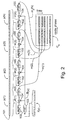
- Fig. 2 shows the correlation step of the method, in which a correlation function matrix C x .is formed of the sample vectors p(1), p(2)...p(N).
- a discrete Hartley transform 102 is performed on each sample vector p(1), p(2)...p(N).
- the number of values used in calculations is preferably 1024, because then the discrete Hartley transform can be implemented in practical applications much more efficiently (with an FHT algorithm) than when 1023 values are used. One way of doing this is to add an extra null as the 1024th element. This has an insignificant effect on the transformation result.
- the reference codes r(x) corresponding to the C/A code of all the satellites of the GPS system are preferably saved in the receiver, whereby x refers to the satellite identifier and is, for example, in the range 1 ⁇ 30. It is not necessary to save the reference codes, but they can also be generated in the receiver.
- the reference code which is selected or generated in the correlation step, is the reference code of the satellite transmitting the signal with which the receiver is being synchronized at any given time.
- the reference code is temporally inverted.
- the inverse reference code r (x) and/or its FHT transformation has often been saved in the memory media of the receiver in advance, but it can be formed of the reference code r(x) in connection with synchronization.
- a multiplication 104 between the Hartley transform result P(i) of each sample vector p(i) and the Hartley transform r ( x ) of the inverse reference code R (x) is performed next in the correlation step.
- M x (i) R (x) ⁇ P(i)
- IFHT inverse Hartley transform 105
- the Hartley transform of the convolution of the time domain signals corresponds to the multiplication of the Hartley transforms of the time domain signals.
- the correlation result then comprises 1023 elements.
- the cross-correlation results m x (i) formed of these different sample vectors p(i) are used to form a correlation function matrix C x , in which the number of rows is the number N of sample vectors.
- the rows of a correlation function matrix C x formed in the correlation step show the cross-correlation of the received signal and the reference code with different phase differences at the intervals of one millisecond.
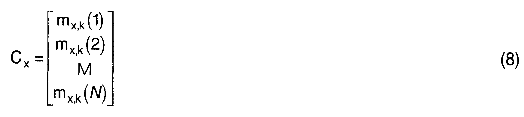
- the correlation function matrix can then be expressed as follows:
- the transpose 106 of the correlation function matrix C x is used; in the transpose the rows represent the signal samples in the time domain in the same manner as in a prior art correlator. Each row corresponds to a certain code phase difference between the received signal and the reference code.
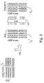
- a Hartley transform 107 is performed on each row of the transpose of this correlation function matrix C x for forming a coherent search matrix A x , whereby a frequency analysis can be performed for determining the real frequency shift. This is illustrated by Fig. 3.
- an incoherent summing step can be performed in the synchronization block 6 to improve the signal-to-noise ratio.
- the sample vector formation step, the correlation step and the analysis step described above are repeated K times (not shown). This number of repetitions K is preferably selected such that the signal-to-noise ratio can be improved sufficiently, but in a reasonable time.
- the values of the elements a x ( i , j ) of the search matrix A x are examined in the acquisition step, and the objective is to find 110 a value, which exceeds the threshold value set in advance and is clearly higher than the other values. If a value like this is found, it expresses the code phase difference and frequency deviation, because it is probably a signal transmitted by a satellite. If the signal is not transmitted by a satellite, but consists of noise or other incidental spurious signals, no remarkable correlation peaks should arise. The code phase difference is seen from the row index of this highest value, and correspondingly the frequency deviation is seen from the column index.
- the example of Fig. 4 illustrates a situation where a value, which is clearly higher than the other values, has been found.
- the frequency range to be examined is changed, and the above mentioned steps are carried out for forming a search matrix.
- the whole band of 6 kHz can be examined by repeating the steps described above as many times as required.
- the steps described above can be repeated for the whole frequency range to be examined, and the search matrices formed at different times of repetition or only the possible peaks can be saved before searching for the highest correlation peak. Then the possibility of false interpretations can be reduced in such a situation, for instance, that the threshold value has been set too small and a spurious signal can cause a false interpretation.
- the receiver can be set to the tracking mode. Reception of data is not successful with weaker signals, and data received via the mobile phone network, for example, must be used instead, which is a situation known as such. Range measurement is still possible with lower accuracy.
- the tracking mode is set by changing the switches (Fig. 1) to another position, whereby the received information is led to the tracking block 11, in which a feedback is also formed for the fine adjustment of the frequency of the numerically controlled oscillator 5.
- the receiver For calculating the location, the receiver performs the signal reception preferably on the basis of signals received from at least four satellites. Then the synchronization described above is repeated when required for the signal of each satellite, and the code of the satellite with which synchronization is performed is selected as the reference sequence r(x) at each time.
- Using a Hartley transform as the time-to-frequency and frequency-to-time transformation also provides the advantage that the same algorithm can be used in both transformations, which can be seen by comparing the formulas (1) and (2).
- the electronics required by the transformations can be implemented with either a circuit area reduced by about a half (an ASIC circuit, for instance) and half lower power consumption than a corresponding implementation with a Fourier transform and about the same processing time, or with a circuit area of the same size and the processing speed even doubled.
- the transformation results H(f) of the Hartley transforms can also be used to calculate the amplitude spectrum and power spectrum of the signal.
- An electronic device 24 which comprises a mobile station and a location determination receiver, is shown in Fig. 5.
- the first antenna 13 is used for the reception of the signal transmitted by the positioning satellites.
- the received signal is led to the first radio part 14, in which the signal is down-converted and digitized.
- the first radio part comprises, among other things, the transformation block 2, digitizing block 3 and multiplier block 4 of the receiver shown in Fig. 1.
- the digitized signal which at this stage preferably comprises the I and Q components, is led to the digital signal processing unit 15, in which, among other things, sample vectors are formed in the sample vector formation block 12.
- Samples are saved in the first memory media 16, which comprise, for instance, read/write memory and preferably also read memory and/or non-volatile read/write memory for saving the program code of the digital signal processing unit 15.
- the signal processing unit 15 also comprises operations of the synchronization block 6, for instance, such as the formation of the correlation function matrix C x,k with, for example, Hartley transformers FFT1, FFT2, ..., FHTN and/or matched filters.
- the digital signal processing unit 15 preferably also includes the formation of a coherent search matrix A x and the performance of an acquisition step.
- the digital signal processing unit 15 transmits information about the calculated phase difference and frequency deviation to the processor block 17, which comprises, for example, a microprocessor and I/O logic.
- the processor block 17 controls the scanning block 8 and the first switch 9.
- the tracking block 11 is preferably at least partly implemented as program instructions of the processor block.
- the second memory media 18 are used as the data memory and program memory of the processor block 17. It is obvious that the first memory media 16 and the second memory media 18 can also comprise common memory. Location determination information can be shown to the user on the display 19.
- the display 19 can then be used for showing telephone call information in a manner known as such.
- the user can control the location determination receiver and the mobile station.
- the coding and decoding of audio signals is performed by means of a codec 21.
- the radio part 22 and the second antenna 23 of the mobile station are also shown in Fig. 5.
- location determination was performed in connection with the receiver.
- at least part of the location determination calculation is performed in connection with the data transfer network.
- a data transfer network can comprise a mobile communication network, for example.
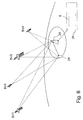
- a calculation server 26 (Fig. 6) or a corresponding unit suitable for location determination calculation has been arranged in a data transfer connection in the data transfer network.
- One possible location for the calculation server is a base station 25 of the mobile communication network, but other alternative locations can also be applied in connection with the present invention.
- the scanning block 8 sets the frequency of the numerically controlled oscillator 5 such that each time the frequencies wanted are received with the receiver 1. Samples of the signal being received are saved in the sample vector formation block 12, preferably as complex sample vectors p(1), p(2)...p(N).
- the correlation step can be partly performed already during sampling, or after N sample vectors p(1), p(2)...p(N) have been formed. If the correlation step is performed in such a manner, for instance, that a time-to-frequency transform is calculated for each sample vector after it has been saved, preferably with a fast Hartley transform (FHT), the same time-to-frequency transformer can be used in all N sample vectors p(1), p(2)...p(N). But if the correlation step is performed after the saving of N sample vectors, a separate time-to-frequency transformer must be used for each sample vector, or the time-to-frequency transforms are performed consecutively for different sample vectors in the same time-to-frequency transformer.
- FHT fast Hartley transform
- the correlation step is performed in the calculation server 26. Then the values of the samples of the sample vectors and the time data of the electronic device 24 are sent preferably by means of the radio part 22 of the mobile station to the mobile communication network. In the mobile communication network, these data are received in the base station 25 and transmitted to the calculation server 26, where they are moved for processing to the block which performs the correlation step, depicted by the synchronization block 6 in Fig. 6.
- a correlation function matrix C x is formed of the sample vectors p(1), p(2)...p(N) in the manner specified in connection with the description of the method according to the first preferred embodiment of the invention.
- a discrete Hartley transform 102 is performed on each sample vector p(1), p(2)...p(N) in accordance with the formula (4) presented above in this specification.
- the reference code of the satellite to the signal of which the receiver is being synchronized is selected or generated each time in the correlation step.
- the reference code is temporally inverted.
- This inverse reference code which is denoted by r (x) in Fig. 2, is treated with a discrete Hartley transform 103, most suitably a fast Hartley transform, in accordance with the formula (5) presented above in this specification.
- a multiplication 104 between the Hartley transform result P(i) of each sample vector p(i) and the Hartley transform R (x) of the inverse reference code r ( x ) is performed next in the correlation step in accordance with the formula (6) presented above in this specification.
- IFHT inverse Hartley transform 105
- a Hartley transform is performed on each row of the transpose of this correlation function matrix C x for forming a coherent search matrix A x , whereby a frequency analysis can be performed for determining the real frequency shift.
- an incoherent summing step can be performed in the synchronization block 6 to improve the signal-to-noise ratio.
- the sample vector formation step, the correlation step and the analysis step described above are repeated K times (not shown). This number of repetitions K is preferably selected such that the signal-to-noise ratio can be improved sufficiently, but in a reasonable time.
- the values of the elements A x of the search matrix a x ( i , j ) are examined in the acquisition step, and the objective is to find 110 a value, which is probably caused by a signal transmitted by a satellite. If such a value is found, the calculation server 26 transmits information of the code phase and the frequency shift to the electronic device 24. But if no such value is found in the search matrix A x , which means that a signal transmitted by the satellite searched for was probably not received in the frequency range examined, the frequency range to be examined is changed, and the above mentioned steps are carried out for forming a search matrix.
- the calculation server 26 transmits to the electronic device 24 information that no signal of the satellite was detected in the frequency range being examined, whereupon the receiver 1 of the electronic device preferably changes the frequency range to be examined and starts performing the steps presented above in this changed frequency range.
- the whole band of 6 kHz can be examined by repeating the steps described above as many times as required.
- the steps described above can be repeated for the whole frequency range to be examined, and the search matrices formed in the calculation server 26 at different times of repetition or only the possible peaks can be saved before searching for the highest correlation peak. Then the possibility of false interpretations can be reduced in such a situation, for instance, that the threshold value has been set too small and a spurious signal can cause a false interpretation.
- the method according to another preferred embodiment of the invention is especially efficient because, among other reasons, there is a very small inaccuracy in the location readings of the calculation server 26 used for location determination, less than one millimeter in practice. This is due to the fact that the location determination server is located in a place known exactly (a base station, for example), and it usually has the Ephemeris data and almanac data of the satellites available each time.
- network-based positioning is to implement all demanding calculations in a calculation server 26 or a corresponding device located in the data transfer network.
- the receiver 1 of an electronic device must then become locked to the signal of at least four satellites and add time information to their code signals for calculating pseudoranges. After this, the electronic device 24 transmits signals to the calculation server 26 for calculating the actual location.
- the receiver 1 may consist, at the minimum, of only the equipment required for carrying out the chip and code phase measurement and for transmitting the measurement results via the network to the server.
Landscapes
- Engineering & Computer Science (AREA)
- Radar, Positioning & Navigation (AREA)
- Remote Sensing (AREA)
- Computer Networks & Wireless Communication (AREA)
- Physics & Mathematics (AREA)
- General Physics & Mathematics (AREA)
- Signal Processing (AREA)
- Position Fixing By Use Of Radio Waves (AREA)
- Synchronisation In Digital Transmission Systems (AREA)
Abstract
- sample vector formation step, in which samples (101) are taken from the received signal for forming the sample vectors (p(1), p(2)...p(N)),
- correlation step (102, 103, 104, 105), in which a
first Hartley transform (
R (x)) is formed on the basis of said reference code (r(x)), and a second Hartley transform (P(i)) is formed on the basis of each sample vector (p(1), p(2)...p(N)), a multiplication is performed between the first Hartley transform (R (x)) formed on the basis of said reference code and the second Hartley transform (P(i)) formed on the basis of each sample vector (p(1), p(2)...p(N)), an inverse Hartley transform is performed on each multiplication result (Mx(i)), and - acquisition step (110), in which the frequency shift and code phase are acquired on the basis of the inverse Hartley transforms (mx(i)) of the multiplication results (Mx(i)).
Description
- Figure 1
- is a simplified block diagram of a receiver, in which the method according to the invention can be applied,
- Figure 2
- shows the correlation step of a method according to a preferred embodiment of the invention as a simplified diagram,
- Figure 3
- shows the analysis step of a method according to a preferred embodiment of the invention as a simplified diagram,
- Figure 4
- shows the acquisition step of a method according to a preferred embodiment of the invention as a simplified diagram,
- Figure 5
- shows an electronic device according to a preferred embodiment of the invention as a simplified block diagram, and
- Figure 6
- illustrates the principle of a positioning system according to a preferred embodiment of the invention as a simplified diagram.



Claims (32)
- A method for performing the operations for synchronizing a receiver (1) with a received code-modulated spread spectrum signal, in which method at least one reference code (r(x)) is used, which reference code corresponds to a code used in the modulation, the frequency shift of the received signal and the code phase of the code used in the modulation are acquired, characterized in that the method includes at least the following steps:sample vector formation step, in which samples (101) are taken from the received signal for forming the sample vectors (p(1), p(2)...p(N)),correlation step (102, 103, 104, 105), in which a first Hartley transform (
R (x)) is formed on the basis of said reference code (r(x)), and a second Hartley transform (P(i)) is formed on the basis of each sample vector (p(1), p(2)...p(N)), a multiplication is performed between the first Hartley transform (R (x)) formed on the basis of said reference code and the second Hartley transform (P(i)) formed on the basis of each sample vector (p(1), p(2)...p(N)), an inverse Hartley transform is performed on each multiplication result (Mx(i)), andacquisition step (110), in which the frequency shift and code phase are acquired on the basis of the inverse Hartley transforms (mx(i)) of the multiplication results (Mx(i)). - A method according to Claim 1, characterized in that in the method the frequency range to be examined is specified, the specified frequency range is divided into two or more parts, whereupon said sample vector formation step and correlation step are performed on each part, and that the method also comprises an analysis step, in which values of the inverse Hartley transforms (mx(i)) of the multiplication results (Mx(i)) are saved for forming a coherent search matrix (Ax), the acquisition step is performed after the examination of the specified frequency range, and the frequency shift and code phase are acquired on the basis of the highest value of the coherent search matrix (Ax).
- A method according to Claim 2, characterized in that a threshold value is specified in the method, and that quantity values of the elements (ax (i,j)) of the coherent search matrix (Ax) that exceed said threshold value are used in the acquisition step for acquiring the frequency shift and code phase.
- A method according to Claim 2 or 3, characterized in that in the method said sample vector formation step, correlation step and analysis step are repeated (108) for forming at least two coherent search matrixes (Ax), and that a summing step (109) is also performed in the method, in which summing step an incoherent search matrix (Sx ) is formed by summing incoherently the values (ax (i,j)) of the equivalent elements of the coherent search matrix (Ax) formed at each time of repetition, and that said incoherent search matrix (Sx ) is used in said acquisition step for acquiring the frequency shift and code phase.
- A method according to Claim 4, characterized in that in the method the frequency range to be examined is specified, the specified frequency range is divided into two or more parts, whereupon said sample vector formation step, correlation step, analysis step and summing step are performed on each part, and values of the elements of the incoherent search matrix (Sx ) are saved, and that the acquisition step is performed after the examination of the specified frequency range, and the frequency shift and code phase are acquired on the basis of the highest value.
- A method according to Claim 4 or 5, characterized in that a threshold value is determined in the method, and that quantity values of the elements of the incoherent search matrix (Sx ) that exceed said threshold value are used in the acquisition step for acquiring the frequency shift and code phase.
- A method according to any one of the claims 1 to 6, characterized in that an inverse code (
r (x)) corresponding to said reference code (r(x)) is used in the correlation step to form the first Hartley transform (R (x)). - A method according to any one of the claims 1 to 6, characterized in that an inverse code corresponding to each sample vector (p(1), p(2)...p(N)) is used in the correlation step to form the second Hartley transform (
P (i)). - A positioning system, which comprises at least a receiver (1), synchronization means (6) for performing synchronization operations to a received code-modulated spread spectrum signal, means (16) for using at least one reference code (r(x)) in connection with the synchronization, which reference code (r(x)) corresponds to a code used in the modulation, and means (15) for acquiring the frequency shift of the received signal and the code phase of the code used in the modulation, characterized in that the synchronization means comprise at least:sample vector formation means (12, 16) for forming sample vectors (p(1), p(2)...p(N)) from the received signal,correlation means (6, FHT1, FHT2...FHTN) for forming a first Hartley transform (
R (x)) on the basis of said reference code (r(x)), and for forming a second Hartley transform (P(i)) on the basis of each sample vector (p(1), p(2)...p(N)), means for performing a multiplication between the first Hartley transform (R (x)) formed on the basis of said reference code and the second Hartley transform (P(i)) formed on the basis of each sample vector (p(1), p(2)...p(N)), and means for performing an inverse Hartley transform on each multiplication result (Mx(i)) for forming a correlation function matrix (Cx),acquisition means (7, 17) for acquiring the frequency shift and code phase by using the values of the inverse Hartley transforms (mx(i)) of the multiplication results (Mx(i)). - A positioning system according to Claim 9, characterized in that the received signals are signals transmitted by satellites of the GPS system.
- A positioning system according to Claim 9 or 10, which comprises a data transfer network, characterized in that at least part of the synchronization means (6) are formed in connection with the data transfer network, and that a data transfer connection is arranged to be established between the data transfer network and the receiver (1).
- A positioning system according to Claim 11, characterized in that the data transfer network comprises at least a mobile communication network.
- A positioning system according to Claim 9 or 10, characterized in that the synchronization means (6) are formed in the receiver (1).
- A receiver (1), which comprises at least synchronization means (6) for performing synchronization operations to a received code-modulated spread spectrum signal, said receiver (1) has means (16) for using at least one reference code (r(x)) in connection with the synchronization, the reference code (r(x)) corresponding to a code used in the modulation, and means (15) for acquiring the frequency shift of the received signal and the code phase of the code used in the modulation, characterized in that the synchronization means comprise at least:sample vector formation means (12, 16) for forming sample vectors (p(1), p(2)...p(N)) from the received signal,correlation means (6, FHT1, FHT2...FHTN) for forming a first Hartley transform (
R (x)) on the basis of said reference code (r(x)), and for forming a second Hartley transform (P(i)) on the basis of each sample vector (p(1), p(2)...p(N)), means for performing a multiplication between the first Hartley transform (R (x)) formed on the basis of said reference code and the second Hartley transform (P(i)) formed on the basis of each sample vector (p(1), p(2)...p(N)), and means for performing an inverse Hartley transform on each multiplication result (Mx(i)) for forming a correlation function matrix (Cx),acquisition means (7, 17) for acquiring the frequency shift and code phase by using the values of the inverse Hartley transforms (mx(i)) of the multiplication results (Mx(i)). - A receiver (1) according to Claim 14, characterized in that it also comprises at leastmeans (17) for specifying the frequency range to be examined, means (5, 8, 9) for dividing the specified frequency range into two or more parts, whereupon the formation of the sample vectors and the formation of the correlation function matrix (Cx) are arranged to be performed for each part,means for forming a coherent search matrix (Ax),means (16) for saving the values of the elements (ax (i,j)) of the coherent search matrix (Ax), andmeans (15) for determining the frequency shift and code phase on the basis of the highest value of the coherent search matrix (Ax).
- A receiver (1) according to Claim 14 or 15,. characterized in that it comprises means (15) for specifying the threshold value, and means (15) for comparing the values of said threshold value and the values of said coherent search matrix (Ax) for determining the frequency shift and code phase.
- A receiver (1) according to any one of the Claims 14, 15 or 16, characterized in that said formation of sample vectors, formation of a correlation function matrix (Cx) and formation of a coherent search matrix (Ax) are arranged to be repeated at least two times for forming a coherent search matrix (Ax,k), and that the receiver (1) also comprises summing means for forming an incoherent search matrix (Sx ) by summing the values (ax,k (i,j)) of the equivalent elements of the coherent search matrix (Ax) formed at each time of repetition, and that said incoherent search matrix (Sx ) is used in the acquisition step for determining the frequency shift and code phase.
- A receiver (1) according to Claim 14, characterized in that it also comprises at leastmeans (17) for specifying the frequency range to be examined,means (5, 8, 9) for dividing the specified frequency range into two or more parts, whereupon the formation of the sample vectors and the formation of the correlation function matrix (Cx) are arranged to be performed for each part,means for forming a coherent search matrix (Ax),means for summing the coherent search matrix (Ax) to the incoherent search matrix (Sx ),means (16) for saving the values of the elements of the incoherent search matrix (Sx ), andmeans (15) for determining the frequency shift and code phase on the basis of the highest value.
- A receiver (1) according to Claim 18, characterized in that it comprises means (15) for specifying the threshold value, and means (15) for comparing the values of said threshold value and the values of said incoherent search matrix (Sx ) for determining the frequency shift and code phase.
- A receiver (1) according to any one of the claims 14 to 19, characterized in that the correlation means comprise means (16) for forming a Hartley transform (
R (x)) of the inverse code (r (x)) corresponding to said reference code (r(x)). - A receiver (1) according to any one of the claims 14 to 19, characterized in that the correlation means comprise means (16) for forming a Hartley transform (
P (i)) of the inverse code corresponding to each sample vector (p(1), p(2)...p(N)). - An electronic device (24), which comprises at least a location determination receiver (1), synchronization means (6) for performing synchronization operations of the location determination receiver (1) to a transmitted code-modulated spread spectrum signal, and in which the location determination receiver (1) includes means (16) for using at least one reference code (r(x)) in connection with the synchronization, the reference code (r(x)) corresponds to a code used in the modulation, and the electronic device comprises means (15) for determining the frequency shift of the transmitted signal and the code phase of the code used in the modulation, characterized in that the synchronization means comprise at least:sample vector formation means (12, 16) for forming sample vectors (p(1), p(2)...p(N)) from the received signal,correlation means (6, FHT1, FHT2...FHTN) for forming a first Hartley transform (
R (x)) on the basis of said reference code (r(x)), and for forming a second Hartley transform (P(i)) on the basis of each sample vector (p(1), p(2)...p(N)), means for performing a multiplication between the first Hartley transform (R (x)) formed on the basis of said reference code and the second Hartley transform (P(i)) formed on the basis of each sample vector (p(1), p(2)...p(N)), and means for performing an inverse Hartley transform on each multiplication result (Mx(i)) for forming a correlation function matrix (Cx), andacquisition means (7, 17) for acquiring the frequency shift and code phase by using the values of the inverse Hartley transforms (mx(i)) of the multiplication results (Mx(i)). - An electronic device (24) according to Claim 22, which comprises means (14, 15, 17) for determining the location of the electronic device (24) and means (18) for saving the location information, characterized in that the electronic device (24) also comprises means (17) for specifying the frequency range to be examined, and means (17, 22, 23) for selecting the starting frequency from said frequency range on the basis of the location information saved in the receiver (1).
- An electronic device (24) according to Claim 22 or 23, characterized in that the correlation means comprise means (16) for forming a Hartley transform (
R (x)) of the inverse code (r (x)) corresponding to said reference code (r(x)). - An electronic device (24) according to Claim 22 or 23, characterized in that the correlation means comprise means (16) for forming a Hartley transform (
P (i)) of the inverse code corresponding to each sample vector (p(1), p(2)...p(N)). - An electronic device (24) according to any one of the Claims 22 to 25, characterized in that it also comprises means for performing data transfer operations.
- An electronic device (24) according to Claim 26, characterized in that it comprises means (22, 23) for establishing a data transfer connection to a data transfer network, whereby the means for determining the location of the electronic device (24) comprise means (22, 23) for transmitting information needed in the location determination to the data transfer network, and means (22, 23) for retrieving information used in the location determination from the data transfer network, whereby at least part of the location determination operations are arranged to be performed in the data transfer network.
- An electronic device (24) according to Claim 26 or 27, characterized in that the means for performing data transfer operations comprise at least means for performing mobile station operations.
- An electronic device (24), which comprises at least a receiver (1) and which electronic device (24) is intended for use in connection with a positioning system, which comprises at least synchronization means (6) for performing synchronization operations of the receiver (1) to a transmitted code-modulated spread spectrum signal, means (16) for using at least one reference code (r(x)) in connection with the synchronization, the reference code (r(x)) corresponding to a code used in the modulation, means (15) for determining the frequency shift of the transmitted signal and the code phase of the code used in the modulation, and a data transfer network, characterized in that the electronic device (24) also comprises at least sample vector formation means (12, 16) for forming sample vectors (p(1), p(2)...p(N)) from the received signal, and transmission means (22, 23) for transmitting the sample vectors (p(1), p(2)...p(N)) and time information to the data transfer network, and that the positioning system also comprises at leastcorrelation means (6, FHT1, FHT2...FHTN) for forming a first Hartley transform (
R (x)) on the basis of said reference code (r(x)), and for forming a second Hartley transform (P(i)) on the basis of each sample vector (p(1), p(2)...p(N)), means for performing a multiplication between the first Hartley transform (R (x)) formed on the basis of said reference code and the second Hartley transform (P(i)) formed on the basis of each sample vector (p(1), p(2)...p(N)), and means for performing an inverse Hartley transform on each multiplication result (Mx(i)) for forming a correlation function matrix (Cx), andacquisition means (7, 17) for acquiring the frequency shift and code phase by using the values of the inverse Hartley transforms (mx(i)) of the multiplication results (Mx(i)). - An electronic device (24) according to Claim 29, characterized in that it also comprises reception means (23, 22) for receiving information about the acquired frequency shift and code phase from the data transfer network.
- An electronic device (24) according to Claim 29 or 30, which is intended for use in connection with a positioning system, and which also comprises at least means (26) for determining the location of an electronic device, characterized in that the electronic device (24) also comprises means (22, 23) for receiving location information from the data transfer network.
- An electronic device (24) according to Claim 29, 30 or 31, characterized in that the means for performing data transfer operations comprise at least means for performing mobile station operations.
Applications Claiming Priority (4)
| Application Number | Priority Date | Filing Date | Title |
|---|---|---|---|
| FI992653 | 1999-12-09 | ||
| FI992653A FI19992653A7 (en) | 1999-12-09 | 1999-12-09 | Method for synchronizing a receiver and a receiver |
| FI20000634 | 2000-03-17 | ||
| FI20000634A FI111109B (en) | 1999-12-09 | 2000-03-17 | Method for synchronizing a receiver, location system, receiver and electronic device |
Publications (2)
| Publication Number | Publication Date |
|---|---|
| EP1107470A2 true EP1107470A2 (en) | 2001-06-13 |
| EP1107470A3 EP1107470A3 (en) | 2003-10-01 |
Family
ID=26160813
Family Applications (1)
| Application Number | Title | Priority Date | Filing Date |
|---|---|---|---|
| EP00660223A Withdrawn EP1107470A3 (en) | 1999-12-09 | 2000-12-07 | Method for synchronizing a receiver in a positioning system |
Country Status (4)
| Country | Link |
|---|---|
| US (1) | US7151793B2 (en) |
| EP (1) | EP1107470A3 (en) |
| JP (1) | JP2001223672A (en) |
| FI (1) | FI111109B (en) |
Cited By (1)
| Publication number | Priority date | Publication date | Assignee | Title |
|---|---|---|---|---|
| WO2007050925A1 (en) * | 2005-10-27 | 2007-05-03 | Qualcomm Incorporated | System and method of frequency acquisition |
Families Citing this family (21)
| Publication number | Priority date | Publication date | Assignee | Title |
|---|---|---|---|---|
| JP3399923B2 (en) | 2000-11-29 | 2003-04-28 | 松下電器産業株式会社 | Communication terminal apparatus and decoding method in communication terminal apparatus |
| US6760365B2 (en) * | 2001-10-11 | 2004-07-06 | Interdigital Technology Corporation | Acquisition circuit for low chip rate option for mobile telecommunication system |
| FI113425B (en) * | 2002-05-16 | 2004-04-15 | Nokia Corp | Procedure for synchronizing a receiver, system and electronic device |
| US7132980B2 (en) * | 2002-11-01 | 2006-11-07 | Sirf Technology, Inc. | Multi-function device with positioning system and shared processor |
| US7262645B2 (en) * | 2002-12-19 | 2007-08-28 | Broadcom Corporation | System and method for adjusting the phase of a frequency-locked clock |
| US7835719B1 (en) * | 2007-05-14 | 2010-11-16 | L-3 Communications Titan Corporation | Detection of signals in a radio network |
| US7839269B2 (en) * | 2007-12-12 | 2010-11-23 | Immersion Corporation | Method and apparatus for distributing haptic synchronous signals |
| US10044402B2 (en) * | 2010-06-25 | 2018-08-07 | Enmodus Limited | Timing synchronization for wired communications |
| US20120195401A1 (en) * | 2011-02-01 | 2012-08-02 | Neal Becker | System and method for correlating received signal over time and frequency |
| US12429599B2 (en) | 2020-07-14 | 2025-09-30 | Spirent Communications Plc | GNSS forecast and spoofing/jamming detection |
| US12282101B2 (en) | 2020-07-14 | 2025-04-22 | Spirent Communications Plc | GNSS forecast and line of sight detection |
| US12265159B2 (en) | 2020-07-14 | 2025-04-01 | Spirent Communications Plc | GNSS forecast impacting receiver startup |
| US11789161B2 (en) | 2020-07-14 | 2023-10-17 | Spirent Communications Plc | Accuracy of a GNSS receiver that has a non-directional antenna |
| US11287531B2 (en) | 2020-07-14 | 2022-03-29 | Spirent Communications, Plc | Architecture for providing forecasts of GNSS obscuration and multipath |
| US12292515B2 (en) | 2020-07-14 | 2025-05-06 | Spirent Communications Plc | Generating and distributing GNSS risk analysis data for facilitating safe routing of autonomous drones |
| US11536855B2 (en) * | 2020-07-14 | 2022-12-27 | Spirent Communications Plc | Path planning using forecasts of obscuration and multipath |
| US12468045B1 (en) | 2020-07-14 | 2025-11-11 | Spirent Communications Plc | Utilizing GNSS risk analysis data for facilitating safe routing of autonomous drones |
| US12298409B2 (en) | 2020-07-14 | 2025-05-13 | Spirent Communications Plc | GNSS forecast and background obscuration prediction |
| DE102021102233B4 (en) * | 2021-02-01 | 2022-08-18 | Recognitionfocus Gmbh | Device and method for correspondence analysis in images |
| US12517264B2 (en) | 2022-09-16 | 2026-01-06 | Spirent Communications Plc | Architecture for providing forecasts of low earth orbit (LEO) satellite obscuration and multipath |
| US12517259B2 (en) | 2022-09-16 | 2026-01-06 | Spirent Communications Plc | Utilizing low earth orbit (LEO) satellite data for obscuration and multipath risk analysis |
Family Cites Families (15)
| Publication number | Priority date | Publication date | Assignee | Title |
|---|---|---|---|---|
| EP0235285A1 (en) | 1985-09-03 | 1987-09-09 | Motorola, Inc. | Apparatus for and method of doppler searching in a digital gps receiver |
| US4905204A (en) * | 1988-09-06 | 1990-02-27 | Exxon Production Research Company | Method of weighting a trace stack from a plurality of input traces |
| US4998111A (en) * | 1989-11-27 | 1991-03-05 | Motorola, Inc. | CPS transform correlation receiver and method |
| US5192957A (en) | 1991-07-01 | 1993-03-09 | Motorola, Inc. | Sequencer for a shared channel global positioning system receiver |
| JPH0659013A (en) | 1992-08-05 | 1994-03-04 | Pioneer Electron Corp | Signal acquisition method for gps receiver |
| FR2715488B1 (en) | 1994-01-21 | 1996-03-22 | Thomson Csf | Method and device enabling a modem to synchronize with a digital data transmitter over the air in the presence of jammers. |
| WO1997014057A1 (en) | 1995-10-09 | 1997-04-17 | Snaptrack, Inc. | A gps receiver and method for processing gps signals |
| US5686683A (en) * | 1995-10-23 | 1997-11-11 | The Regents Of The University Of California | Inverse transform narrow band/broad band sound synthesis |
| FI102338B1 (en) | 1996-05-21 | 1998-11-13 | Nokia Mobile Phones Ltd | Recipient's self-synchronization in idle condition |
| US5764690A (en) * | 1996-06-04 | 1998-06-09 | Motorola, Inc. | Apparatus for despreading and demodulating a burst CDMA signal |
| FI102340B (en) | 1997-01-16 | 1998-11-13 | Nokia Telecommunications Oy | Procedure for data communication and radio systems |
| JP3028800B2 (en) * | 1998-05-01 | 2000-04-04 | 日本電気株式会社 | CDMA cellular system and spreading code detection method in CDMA cellular system |
| EP0971485A1 (en) | 1998-07-08 | 2000-01-12 | Siemens Aktiengesellschaft | Multiuser detection in CDMA using a correlation matrix |
| US6463043B1 (en) * | 1998-11-25 | 2002-10-08 | Nortel Networks Limited | Carrier phase recovery of multi-rate signals |
| US6606349B1 (en) * | 1999-02-04 | 2003-08-12 | Sirf Technology, Inc. | Spread spectrum receiver performance improvement |
-
2000
- 2000-03-17 FI FI20000634A patent/FI111109B/en not_active IP Right Cessation
- 2000-12-07 EP EP00660223A patent/EP1107470A3/en not_active Withdrawn
- 2000-12-08 US US09/732,828 patent/US7151793B2/en not_active Expired - Fee Related
- 2000-12-11 JP JP2000376497A patent/JP2001223672A/en active Pending
Cited By (1)
| Publication number | Priority date | Publication date | Assignee | Title |
|---|---|---|---|---|
| WO2007050925A1 (en) * | 2005-10-27 | 2007-05-03 | Qualcomm Incorporated | System and method of frequency acquisition |
Also Published As
| Publication number | Publication date |
|---|---|
| US20010004380A1 (en) | 2001-06-21 |
| EP1107470A3 (en) | 2003-10-01 |
| FI111109B (en) | 2003-05-30 |
| US7151793B2 (en) | 2006-12-19 |
| FI20000634A0 (en) | 2000-03-17 |
| FI20000634A7 (en) | 2001-06-10 |
| JP2001223672A (en) | 2001-08-17 |
Similar Documents
| Publication | Publication Date | Title |
|---|---|---|
| US7151793B2 (en) | Method for synchronizing a receiver, a positioning system, a receiver and an electronic device | |
| US6909738B2 (en) | Method in a receiver and a receiver | |
| EP1712010B1 (en) | Rapid acquisition methods and apparatus for gps signals background | |
| EP1322044B1 (en) | Method and apparatus for detecting spread spectrum signal spread code synchronization | |
| KR100942207B1 (en) | Method and apparatus for computing signal correlation at multiple resolutions | |
| US6792035B2 (en) | Method and apparatus for reducing the effect of multipath propagation in a received signal | |
| US9252826B2 (en) | Method and apparatus for reducing the time required to acquire a GPS signal | |
| KR100937130B1 (en) | Method and apparatus for performing signal correlation using historical correlation data | |
| EP1107018A2 (en) | Method for synchronizing a receiver | |
| US5825327A (en) | GPS receivers and garments containing GPS receivers and methods for using these GPS receivers | |
| EP1529224A1 (en) | Method and apparatus for performing signal correlation at multiple resolutions to mitigate multipath interference | |
| US8254512B2 (en) | Method and apparatus for increasing coherent integration length while receiving a positioning signal | |
| EP1379010B1 (en) | A method, a system and an electronic device for synchronizing a receiver | |
| US7421011B2 (en) | Performing an acquisition in a receiver | |
| US7308021B2 (en) | Method in the synchronization of a receiver, and a receiver | |
| HK1099425B (en) | Rapid acquisition methods and apparatus for gps signals background | |
| HK1109930A (en) | Method and apparatus for increasing coherent integration length while receiving a positioning signal |
Legal Events
| Date | Code | Title | Description |
|---|---|---|---|
| PUAI | Public reference made under article 153(3) epc to a published international application that has entered the european phase |
Free format text: ORIGINAL CODE: 0009012 |
|
| AK | Designated contracting states |
Kind code of ref document: A2 Designated state(s): AT BE CH CY DE DK ES FI FR GB GR IE IT LI LU MC NL PT SE TR |
|
| AX | Request for extension of the european patent |
Free format text: AL;LT;LV;MK;RO;SI |
|
| RAP1 | Party data changed (applicant data changed or rights of an application transferred) |
Owner name: NOKIA CORPORATION |
|
| PUAL | Search report despatched |
Free format text: ORIGINAL CODE: 0009013 |
|
| AK | Designated contracting states |
Kind code of ref document: A3 Designated state(s): AT BE CH CY DE DK ES FI FR GB GR IE IT LI LU MC NL PT SE TR |
|
| AX | Request for extension of the european patent |
Extension state: AL LT LV MK RO SI |
|
| 17P | Request for examination filed |
Effective date: 20040319 |
|
| AKX | Designation fees paid |
Designated state(s): AT BE CH CY DE DK ES FI FR GB GR IE IT LI LU MC NL PT SE TR |
|
| STAA | Information on the status of an ep patent application or granted ep patent |
Free format text: STATUS: THE APPLICATION IS DEEMED TO BE WITHDRAWN |
|
| 18D | Application deemed to be withdrawn |
Effective date: 20070703 |