EP1107390A2 - A method for mounting a connector on a panel and a connector assembly - Google Patents
A method for mounting a connector on a panel and a connector assembly Download PDFInfo
- Publication number
- EP1107390A2 EP1107390A2 EP00126224A EP00126224A EP1107390A2 EP 1107390 A2 EP1107390 A2 EP 1107390A2 EP 00126224 A EP00126224 A EP 00126224A EP 00126224 A EP00126224 A EP 00126224A EP 1107390 A2 EP1107390 A2 EP 1107390A2
- Authority
- EP
- European Patent Office
- Prior art keywords
- connector
- panel
- base plate
- spring
- stationary
- Prior art date
- Legal status (The legal status is an assumption and is not a legal conclusion. Google has not performed a legal analysis and makes no representation as to the accuracy of the status listed.)
- Withdrawn
Links
- 238000000034 method Methods 0.000 title claims abstract description 23
- 238000010276 construction Methods 0.000 description 5
- 238000010586 diagram Methods 0.000 description 3
- 230000004048 modification Effects 0.000 description 2
- 238000012986 modification Methods 0.000 description 2
- 239000000463 material Substances 0.000 description 1
- 239000002184 metal Substances 0.000 description 1
- 239000011347 resin Substances 0.000 description 1
- 229920005989 resin Polymers 0.000 description 1
- 230000000717 retained effect Effects 0.000 description 1
Images


Classifications
-
- H—ELECTRICITY
- H01—ELECTRIC ELEMENTS
- H01R—ELECTRICALLY-CONDUCTIVE CONNECTIONS; STRUCTURAL ASSOCIATIONS OF A PLURALITY OF MUTUALLY-INSULATED ELECTRICAL CONNECTING ELEMENTS; COUPLING DEVICES; CURRENT COLLECTORS
- H01R13/00—Details of coupling devices of the kinds covered by groups H01R12/70 or H01R24/00 - H01R33/00
- H01R13/73—Means for mounting coupling parts to apparatus or structures, e.g. to a wall
- H01R13/74—Means for mounting coupling parts in openings of a panel
- H01R13/748—Means for mounting coupling parts in openings of a panel using one or more screws
Definitions
- This invention relates to a method of mounting a connector on a panel.
- this invention relates to an improvement of the method of mounting a connector on a panel in an office appliance, such as a copier/duplicator, or a printer, or a household appliance, and the like, which has a cover to an interior that is opened and closed or which has a member that is frequently detached during the time the appliance is out of order.
- the connectors that engage with one another are respectively mounted on a stationary panel and a movable panel, which is opened from and closed to or detached from the stationary panel.
- This invention further relates to a connector assembly that improves the mounting operation of the connector.
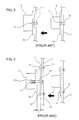
- a female connector 2 is fixed on the stationary panel 1
- a male connector 4 is fixed on the movable panel 3, so that the cover may be attached to, opened from and closed to the stationary panel 1.
- a bolt hole is provided on each of the flange portions 2a and 4a, which extend outwardly from an outer periphery of connector housing of each of the connectors 2 and 4.
- bolts 5 and 6 are inserted into bolt holes provided in the panels 1 and 3.
- the connectors 2 and 4 are fixed on the panels 1 and 3 by fastening with bolts 5 and 6 and nuts 7 and 8.
- a base plate 9 is fixed to the stationary panel 1, and then the female connector 2, is coupled to the base plate 9 using a bolt 10 having a spring.
- the bolt 10 having a coil spring 11 is inserted into a through hole provided in the flange portion 2a of the female connector 2, and a through hole provide in the base plate 9.
- the coil spring 11 extends between the flange portion 2a and a bolt head portion 10a.
- a nut 12 is threaded onto the end of the bolt 10 extending from the base plate 9 to secure the connector 2 on the panel 1.
- the connector 4 is directly fixed on the movable panel 3.
- the present invention is provided in view of the above-described problems, and an objective of the present invention is to improve the mounting operation of a connector to a panel.
- the present invention provides a method of mounting a connector of a pair of connectors that are respectively mounted on a stationary panel and a movable panel, and that engage with one another.
- a first connector of the pair of the connectors is directly fixed to one of the stationary panel and the movable panel.
- a second connector is movably mounted on the other one of the stationary panel and the movable panel via a spring.
- the method of mounting the connector includes integrating the second connector with a base plate to form an assembly by using a bolt having the spring, prior to mounting the second connector on the one of the stationary panel and the movable panel, and fixing the base plate of the assembly on the one of the stationary panel and the movable panel so as to movably mount the second connector on the one of the stationary panel and the movable panel.
- the second connector has a flange portion that extends outwardly from an outer periphery of the second connector and that has a first through hole.
- the base plate has a second through hole that is aligned with the first through hole in the flange of the second connector.
- the bolt having the spring is inserted into the first through hole and the second through hole.
- the spring extends between the flange portion of the second connector and an end of the bolt extending from the flange portion of the second connector.
- a nut is threaded on the end of the bolt.
- the spring can extend between a head portion of the bolt and the flange portion of the second connector.
- a nut is threaded onto the end of the bolt extending from the base plate.
- the second connector which is movably mounted via the spring, can be provided either on the stationary panel or the movable panel. However, it is preferable to mount the second connector on the stationary panel, and to fixedly mount the first connector, which engages with the second connector, on the movable panel.
- a connector assembly in another aspect of the present invention, includes a connector having a flange portion that extends outwardly from an outer periphery of the connector and has a first through hole, a base plate having a second through hole that is aligned with the first through hole, an elongate member inserted into the first and second through holes aligned each other, and a spring that is provided around the elongate member and presses that connector toward the base plate so that the base plate and the flange portion contact each other.
- the spring can be provided so as to extend between the flange portion and a first end portion of the elongate member, or can be provided so as to extend between the flange portion and a second end portion of the elongate member.
- the elongate member may be formed as a bolt, with the first end being threaded to receive a nut and the second end having a head.
- the connector is integrated with the base plate and the spring for absorbing an impact force to form an assembly prior to mounting the connector to the panel. Therefore, when the connector is mounted on the panel, the base plate of the assembly is simply fixed to the panel. As a result, the efficiency of the connector mounting operation is substantially improved. Further, because of the reduction of the operational cost, the total cost can be reduced.
- Figs. 1(A) and 1(B) respectively show a perspective view and a side view illustrating an embodiment according to the present invention.
- Fig. 2(A) is a side view illustrating a connector mounted on a panel.
- Fig. 2(B) is a side view illustrating connectors mounted on panels to engage with each other.
- Fig. 3 is a partial cross-sectional view illustrating a modification of the embodiment according to the present invention.
- Fig. 4 is a schematic diagram illustrating another modification of the embodiment according to the present invention.
- Fig. 5 is a schematic diagram illustrating a conventional construction.
- Figs. 6(A) and 6(B) are schematic diagrams illustrating another conventional construction.
- FIGs. 1(A) and 1(B) show a connector assembly, which is integrally assembled prior to the mounting operation of a connector on a panel.
- the connector assembly has a flange portion 22 extending outwardly from an outer periphery of the connector housing 21 of a female connector (abbreviated as a connector, in the following) 20.
- a pair of through holes 23 to insert bolts are provided in the right and left sides of the flange portion 22.
- the base plate 25 has through holes 26 that are aligned with the through holes 23 in the flange portion 22 of the connector 20. Further, a pair of panel mounting holes 27 are provided in right and left side portions of the base plate 25 extending past the flange portion 22 of the connector 20.
- the base plate 25 has a large aperture 25a into which a connector 40, which is mounted on the movable panel 3 to engage with the connector 20, can be inserted.
- the base plate 25 can be made of a resin or a metal.
- the connector 20 and the base plate 25 are integrally assembled by using a bolt 30 having a shank portion 30a that receives a coil spring 29.
- the bolt 30 is inserted into the through hole 26 in the base plate 25 and the through hole 23 in the connector 20.
- the bolt head portion 30b is retained on the base plate 25.
- the shank portion 30a that extends from the through hole 23 receives the coil spring 29.
- a nut 31 is threaded onto the end of the shank portion 30a of the bolt so as to secure the base plate 25 and the panel 1.
- the connector 20 and the base plate 25 are integrated into a single unit assembly in which the coil spring 29 presses the flange portion 22 toward the base plate 25 so that the flange portion 22 contacts the base plate 25.
- the connector 20 which is integrated with the base plate 25 is mounted on the stationary panel 1 as shown in Fig. 2(A)
- the bolt 35 is inserted into the panel mounting hole 27 provided in the base plate 25 and the mounting hole la in the stationary panel 1.
- the connector 20 is fastened to the panel 1 with a nut threaded onto the bolt 35.
- the mounting hole la in the stationary panel 1 can be provided as a screw hole.
- the connector 20 integrated with the base plate 25 is fixed to the stationary panel 1 with a machine screw.
- the male connector (abbreviated as a connector, in the following) 40 is directly fixed to the movable panel 3 by using bolts 41.
- the connector 40 on the movable panel 3 is inserted into and engages with the connector 20 on the stationary panel 1.
- the connector 40 engages with the connector 20 with a large impact force. If this impact force is applied to the connector 20, the connector 20 moves back with the stroke L from the base plate 25 against the bias of the spring 29 to reduce the impact force.
- the connectors 20 and 40 which engage with one another, are prevented from being damaged due to the impact force.
- the present invention is not limited to the embodiment described above. Instead, as shown in Fig. 3, the bolt 30 provided with the coil spring 29 therearound in advance, can be inserted into the through hole 23 provided in the flange portion 22 of the connector 20 and the through hole 26 provided in the base plate 25, and then the nut 31 is threaded onto the bolt shank portion 30a extending from the base plate 25 so that the coil spring extends between the bolt head portion 30b and the flange portion 22. Similarly to the embodiment as shown in Fig. 2(A), the spring 29 presses the flange portion 22 toward the base plate 25 so that the flange portion 22 contacts the base plate.
- the connector 20, which is biased by the spring is mounted on the stationary panel 1.
- the connector 40, which is biased by the spring is mounted on the movable panel 3, and to fix another connector 20 on the stationary panel 1 directly.
- the base plate and the connector are assembled by using bolts.
- any elongate member, such as a rivet instead of the bolt.
- a connector that is to be movably mounted on a panel via a spring is assembled to a base plate by using a bolt having a spring mounted thereon so that the connector and the base plate are integrated into a unit prior to mounting the connector on the panel. Accordingly, when the connector is mounted on a panel, the base plate is simply fixed on the panel. Thus, the mounting operation of the connector on the panel becomes easier than prior constructions. Further, the cost of the mounting operation can be substantially reduced.
- a method of mounting a connector of a pair of connectors that are respectively mounted on a stationary panel and a movable panel, and that engage with one another.
- a first connector of the pair of connectors is movably mounted on one of the stationary panel and the movable panel via a spring.
- the first connector has a flange portion that extends outwardly from an outer periphery of the first connector and has a first through hole.
- a base plate has a second through hole that is aligned with the first through hole.
- the method of mounting the connector includes integrating the second connector and the base plate into an assembly by inserting a bolt having the spring into the first and the second through holes prior to the second connector being mounted on one of the stationary panel and the movable panel, and then fixing the base plate of the assembly on the one of the stationary panel and the movable panel so as to movably mount the second connector on the one of the stationary panel and the movable panel.
- the spring can extend between the flange portion and an end of the bolt extending from the flange portion.
Landscapes
- Connector Housings Or Holding Contact Members (AREA)
- Details Of Connecting Devices For Male And Female Coupling (AREA)
Abstract

Description
Claims (13)
- A method of mounting a connector of a pair of connectors that are respectively mounted on a stationary panel and a movable panel, and that engage with one another, a first connector of the pair of connectors being directly fixed to one of the stationary panel and the movable panel, a second connector of the pair of the connectors being movably mounted on the other of the stationary panel and the movable panel via a spring, said method comprising:integrating said second connector with a base plate to form an assembly by using a bolt provided with said spring prior to mounting said second connector on the one of the stationary panel and the movable panel, said base plate being provided between said second connector and one of the stationary panel and the movable panel, said assembly comprising:said second connector having a flange portion that extends from an outer periphery of said second connector, said flange portion having a first through hole,said base plate having a second through hole that is aligned with said first through hole, andsaid bolt having the spring, being inserted into said first and second through holes; andfixing said base plate of said assembly to the one of the stationary panel and the movable panel so as to movably mount said second connector on the one of the stationary panel and the movable panel.
- The method of mounting a connector according to claim 1, wherein said second connector is movably mounted on the stationary panel via said spring, and said first connector is fixedly mounted on the movable panel.
- The method of mounting a connector according to claim 1, wherein said second connector is movably mounted on the movable panel via said spring, and said first connector is fixedly mounted on the stationary panel.
- The method of mounting a connector according to claim 1, wherein said first connector comprises a plurality of first connectors and said second connector comprises a plurality of second connectors, each plurality of first connectors engaging with each plurality of second connectors, and
wherein said plurality of second connectors are mounted on a single base plate. - The method of mounting a connector according to claim 1, wherein said spring extends between said flange portion of said second connector and an end of said bolt extending from said flange portion of said second connector, and a nut threaded onto said end of said bolt to secure said base plate to said one of the stationary panel and the movable panel.
- The method of mounting a connector according to claim 1, wherein said spring extends between a head portion of said bolt and said flange portion of said second connector, and wherein a nut is threaded onto an end of said bolt extending from said base plate to secure said base plate to said one of the stationary panel and the movable panel.
- A method of mounting a connector of a pair of connectors that are respectively mounted on a stationary panel and a movable panel, and that engage with one another, a first connector of the pair of connectors being directly fixed on one of the stationary panel and the movable panel, a second connector of the pair of the connectors being movably mounted on the other of the stationary panel and the movable panel via a spring, said method comprising:aligning a first through hole provided in a flange portion extending from an outer periphery of said second connector, with a second through hole provided in a base plate provided between said second connector and one of the stationary plate and the movable plate;inserting a bolt having said spring into said first and second through holes aligned each other so that said spring extends between an end of said bolt extending from said flange portion and the flange portion; andfixing said base plate on the one of the stationary panel and the movable panel.
- The connector mounting method according to claim 7, wherein said base plate is fixed on the stationary panel to movably mount said second connector on the stationary panel via said spring, and said first connector is fixedly mounted on the movable panel.
- A connector assembly comprising:a connector having a flange portion extends outwardly from an outer periphery of said connector, said flange having a first through hole;a separate base plate having a second through hole aligned with said first through hole;an elongate member inserted into said first and second through holes aligned each other; anda spring provided around said elongate member to press said connector between said base plate so that said base plate and said flange portion contact each other.
- The connector assembly according to claim 9, wherein said elongate member include a first abutment member at a first end thereof and a second abutment member at a second end thereof.
- The connector assembly according to claim 10, wherein said spring extends between said flange portion and the first abutment member of said elongate member.
- The connector assembly according to claim 10, wherein said spring extends between said flange portion and the second abutment member of said elongate member.
- The connector assembly according to claim 10, wherein said elongate member comprises a bolt, and said first abutment member is formed as a head of the bolt, and said second abutment member is formed as a nut threaded on said second end.
Applications Claiming Priority (2)
| Application Number | Priority Date | Filing Date | Title |
|---|---|---|---|
| JP33994999 | 1999-11-30 | ||
| JP33994999A JP2001155826A (en) | 1999-11-30 | 1999-11-30 | Connector mounting structure to panel |
Publications (2)
| Publication Number | Publication Date |
|---|---|
| EP1107390A2 true EP1107390A2 (en) | 2001-06-13 |
| EP1107390A3 EP1107390A3 (en) | 2002-08-14 |
Family
ID=18332295
Family Applications (1)
| Application Number | Title | Priority Date | Filing Date |
|---|---|---|---|
| EP00126224A Withdrawn EP1107390A3 (en) | 1999-11-30 | 2000-11-30 | A method for mounting a connector on a panel and a connector assembly |
Country Status (3)
| Country | Link |
|---|---|
| US (1) | US6346007B2 (en) |
| EP (1) | EP1107390A3 (en) |
| JP (1) | JP2001155826A (en) |
Cited By (1)
| Publication number | Priority date | Publication date | Assignee | Title |
|---|---|---|---|---|
| EP2937948A4 (en) * | 2013-01-23 | 2015-12-30 | Huawei Tech Co Ltd | Blind-mate integrated connector |
Families Citing this family (27)
| Publication number | Priority date | Publication date | Assignee | Title |
|---|---|---|---|---|
| US6706000B2 (en) * | 1997-11-21 | 2004-03-16 | Amira Medical | Methods and apparatus for expressing body fluid from an incision |
| JP2002170645A (en) * | 2000-11-23 | 2002-06-14 | Hon Hai Precision Industry Co Ltd | Connector metal case and manufacturing method thereof |
| US6592387B2 (en) * | 2000-12-22 | 2003-07-15 | Honeywell International Inc. | Spring-loaded connector setup for blind mating and method for using the same |
| DE10258106A1 (en) * | 2002-12-11 | 2004-06-24 | Volkswagen Ag | Electric plug-in connection for sliding door on road vehicle has plug and/or bushing displaceably mounted in relation to respective housing |
| TW572419U (en) * | 2003-03-18 | 2004-01-11 | Delta Electronics Inc | Power line securing module for electronic apparatus |
| JP2005050564A (en) * | 2003-07-29 | 2005-02-24 | Jst Mfg Co Ltd | connector |
| US6997741B2 (en) * | 2003-11-15 | 2006-02-14 | Cray Inc. | Systems and methods for partitioning banks of processors in large computer systems |
| US7267568B2 (en) * | 2004-04-21 | 2007-09-11 | Bigband Networks Bas, Inc. | Floating connectors |
| US20060099845A1 (en) * | 2004-11-07 | 2006-05-11 | Lear Corporation | Connector support for direct connection to a printed circuit board |
| US7121857B1 (en) * | 2005-03-25 | 2006-10-17 | Emc Corporation | Tolerance-absorbing interconnect system using a spring-loaded connector |
| US7452225B2 (en) * | 2005-10-20 | 2008-11-18 | Hewlett-Packard Development Company, L.P. | Computer device with retractable connector |
| JP5272674B2 (en) * | 2007-11-16 | 2013-08-28 | 富士ゼロックス株式会社 | Image forming apparatus |
| US7690108B2 (en) * | 2008-08-22 | 2010-04-06 | International Business Machines Corporation | Self-compensating connector support method and apparatus |
| US8152562B2 (en) * | 2009-04-02 | 2012-04-10 | Fci Americas Technology Llc | Cable panel mount |
| TWI487445B (en) * | 2010-03-26 | 2015-06-01 | Hon Hai Prec Ind Co Ltd | Connector and printed circuit board assmebly |
| CN102208730B (en) * | 2010-03-29 | 2015-04-01 | 鸿富锦精密工业(深圳)有限公司 | Combined structure of connector and circuit board |
| DE102010045590A1 (en) * | 2010-09-16 | 2012-03-22 | Airbus Operations Gmbh | Device for fastening an electrical device to an aircraft monument |
| CN102957066A (en) * | 2011-08-23 | 2013-03-06 | 鸿富锦精密工业(深圳)有限公司 | Connector fixing device |
| CN103330532B (en) * | 2013-07-18 | 2015-12-30 | 厦门瑞尔特卫浴科技股份有限公司 | The pre-arrangement of toilet cover and toilet fast assembling-disassembling |
| TWI507852B (en) * | 2013-10-29 | 2015-11-11 | Wistron Corp | Docking station and electronic apparatus |
| FR3033673B1 (en) * | 2015-03-13 | 2018-11-16 | Thales | CONNECTOR FOR ELECTRONIC EQUIPMENT ON BOARD WITH TWO CONNECTORS |
| CN109314518B (en) | 2016-04-22 | 2022-07-29 | 康杜实验室公司 | High performance phase locked loop |
| US10998742B2 (en) * | 2017-01-05 | 2021-05-04 | T-Conn Precision Corporation | Fixing connector with charging module |
| US11171450B2 (en) | 2019-07-12 | 2021-11-09 | International Business Machines Corporation | Method and apparatus for the alignment and locking of removable elements with a connector |
| US11417989B2 (en) * | 2020-03-12 | 2022-08-16 | Koninklijke Fabriek Inventum B.V. | Galley insert power connector assembly with spring assemblies |
| US11949189B2 (en) * | 2021-08-17 | 2024-04-02 | Te Connectivity Solutions Gmbh | Circuit board assembly for a communication system |
| US11923638B2 (en) * | 2021-11-02 | 2024-03-05 | Te Connectivity Solutions Gmbh | Circuit board assembly for a communication system |
Family Cites Families (8)
| Publication number | Priority date | Publication date | Assignee | Title |
|---|---|---|---|---|
| US2978800A (en) * | 1955-11-30 | 1961-04-11 | Sperry Rand Corp | Memory plane wiring techniques |
| JPH07114730B2 (en) | 1989-08-15 | 1995-12-13 | 株式会社ジャムコ | Serving vehicle with heating device, tray for the serving vehicle, and casserole |
| US5092774A (en) * | 1991-01-09 | 1992-03-03 | National Semiconductor Corporation | Mechanically compliant high frequency electrical connector |
| US5383790A (en) * | 1993-11-19 | 1995-01-24 | G & H Technology, Inc. | Connector with floating self-alignment and zero impulse separation mechanisms |
| JP3113971B2 (en) | 1996-09-13 | 2000-12-04 | 日本電気エンジニアリング株式会社 | Floating connector |
| US6007363A (en) * | 1998-03-18 | 1999-12-28 | Thomson Consumer Electronics, Inc. | Magnetically latchable device for electrically coupling a power source to a circuit |
| TW389402U (en) * | 1998-11-17 | 2000-05-01 | Hon Hai Prec Ind Co Ltd | Guiding device for connector |
| TW394466U (en) * | 1998-11-17 | 2000-06-11 | Hon Hai Prec Ind Co Ltd | Electronic component guiding device |
-
1999
- 1999-11-30 JP JP33994999A patent/JP2001155826A/en not_active Withdrawn
-
2000
- 2000-11-29 US US09/725,023 patent/US6346007B2/en not_active Expired - Fee Related
- 2000-11-30 EP EP00126224A patent/EP1107390A3/en not_active Withdrawn
Cited By (2)
| Publication number | Priority date | Publication date | Assignee | Title |
|---|---|---|---|---|
| EP2937948A4 (en) * | 2013-01-23 | 2015-12-30 | Huawei Tech Co Ltd | Blind-mate integrated connector |
| US9614325B2 (en) | 2013-01-23 | 2017-04-04 | Huawei Technologies Co., Ltd. | Blind-mate integrated connector |
Also Published As
| Publication number | Publication date |
|---|---|
| JP2001155826A (en) | 2001-06-08 |
| EP1107390A3 (en) | 2002-08-14 |
| US20010002344A1 (en) | 2001-05-31 |
| US6346007B2 (en) | 2002-02-12 |
Similar Documents
| Publication | Publication Date | Title |
|---|---|---|
| US6346007B2 (en) | Method for mounting a connector on a panel and a connector assembly | |
| US5294223A (en) | Self-clinching fastener for electrical components | |
| WO1999066216A1 (en) | Jack-out captivated screw | |
| WO1993000517A1 (en) | Electrical contact nut | |
| US6435297B1 (en) | Vehicle component mounting assembly | |
| CA1187159A (en) | Mounting system for panel mounted devices | |
| JP3116271B2 (en) | Vehicle motor | |
| US6971146B2 (en) | Fastening spring | |
| JP2007162878A (en) | Fastening mechanism and fastening device | |
| US8075146B2 (en) | Fixing device for position regulating mechanisms for external rear-view mirrors on motor vehicles | |
| EP0966065A2 (en) | Mounting for an electrical connection box | |
| JP3080917B2 (en) | Power transmission cable mounting terminal structure | |
| JP3004874B2 (en) | Nut and nut holding member | |
| US5911590A (en) | Securing structure for unit component | |
| KR102907920B1 (en) | Part fixing bolt for vehicle body | |
| JP2523499Y2 (en) | Recoil starter mounting structure | |
| CN222767740U (en) | A buckle automatic assembly machine | |
| EP1121729B1 (en) | Multiple axis connection system | |
| CN112004349B (en) | Locking device and shell | |
| JPH1130241A (en) | Yoke clips | |
| JP3014601B2 (en) | Assembly structure of coil spring for over center | |
| EP1154164B1 (en) | Method of assembly of first and second component | |
| KR200145839Y1 (en) | Cooler Bracket Unit for Car Air Conditioner | |
| JPH0116653Y2 (en) | ||
| WO1997041716B1 (en) | Surface-mounted attachment means and use thereof |
Legal Events
| Date | Code | Title | Description |
|---|---|---|---|
| PUAI | Public reference made under article 153(3) epc to a published international application that has entered the european phase |
Free format text: ORIGINAL CODE: 0009012 |
|
| 17P | Request for examination filed |
Effective date: 20001130 |
|
| AK | Designated contracting states |
Kind code of ref document: A2 Designated state(s): AT BE CH CY DE DK ES FI FR GB GR IE IT LI LU MC NL PT SE TR |
|
| AX | Request for extension of the european patent |
Free format text: AL;LT;LV;MK;RO;SI |
|
| PUAL | Search report despatched |
Free format text: ORIGINAL CODE: 0009013 |
|
| AK | Designated contracting states |
Kind code of ref document: A3 Designated state(s): AT BE CH CY DE DK ES FI FR GB GR IE IT LI LU MC NL PT SE TR |
|
| AX | Request for extension of the european patent |
Free format text: AL;LT;LV;MK;RO;SI |
|
| AKX | Designation fees paid |
Designated state(s): DE FR GB |
|
| STAA | Information on the status of an ep patent application or granted ep patent |
Free format text: STATUS: THE APPLICATION IS DEEMED TO BE WITHDRAWN |
|
| 18D | Application deemed to be withdrawn |
Effective date: 20060112 |