EP1107279A2 - Incandescent lamp for use in a reflector - Google Patents
Incandescent lamp for use in a reflector Download PDFInfo
- Publication number
- EP1107279A2 EP1107279A2 EP00310897A EP00310897A EP1107279A2 EP 1107279 A2 EP1107279 A2 EP 1107279A2 EP 00310897 A EP00310897 A EP 00310897A EP 00310897 A EP00310897 A EP 00310897A EP 1107279 A2 EP1107279 A2 EP 1107279A2
- Authority
- EP
- European Patent Office
- Prior art keywords
- optical disc
- spring
- reflector
- mantle
- incandescent lamp
- Prior art date
- Legal status (The legal status is an assumption and is not a legal conclusion. Google has not performed a legal analysis and makes no representation as to the accuracy of the status listed.)
- Withdrawn
Links
- 230000003287 optical effect Effects 0.000 claims abstract description 74
- 239000002184 metal Substances 0.000 claims abstract description 35
- 238000004873 anchoring Methods 0.000 claims abstract description 7
- 239000000463 material Substances 0.000 claims abstract description 6
- 210000002105 tongue Anatomy 0.000 description 10
- 238000005452 bending Methods 0.000 description 7
- 230000006835 compression Effects 0.000 description 5
- 238000007906 compression Methods 0.000 description 5
- 238000004519 manufacturing process Methods 0.000 description 5
- 238000000034 method Methods 0.000 description 4
- 238000010276 construction Methods 0.000 description 3
- 238000005520 cutting process Methods 0.000 description 3
- 239000011521 glass Substances 0.000 description 3
- 230000000284 resting effect Effects 0.000 description 3
- 229910000639 Spring steel Inorganic materials 0.000 description 2
- 238000005096 rolling process Methods 0.000 description 2
- 238000007789 sealing Methods 0.000 description 2
- 230000000712 assembly Effects 0.000 description 1
- 238000000429 assembly Methods 0.000 description 1
- 230000007547 defect Effects 0.000 description 1
- 239000000428 dust Substances 0.000 description 1
- 238000005516 engineering process Methods 0.000 description 1
- 229910052736 halogen Inorganic materials 0.000 description 1
- 150000002367 halogens Chemical class 0.000 description 1
- 230000000149 penetrating effect Effects 0.000 description 1
- 238000003825 pressing Methods 0.000 description 1
- 238000006748 scratching Methods 0.000 description 1
- 230000002393 scratching effect Effects 0.000 description 1
- 238000003860 storage Methods 0.000 description 1
- 230000008961 swelling Effects 0.000 description 1
Images



Classifications
-
- H—ELECTRICITY
- H01—ELECTRIC ELEMENTS
- H01K—ELECTRIC INCANDESCENT LAMPS
- H01K1/00—Details
- H01K1/42—Means forming part of the lamp for the purpose of providing electrical connection, or support for, the lamp
- H01K1/46—Means forming part of the lamp for the purpose of providing electrical connection, or support for, the lamp supported by a separate part, e.g. base, cap
Definitions
- This invention relates to an incandescent lamp for use in a reflector, and, more particularly, to an incandescent lamp suitable for being replaceable fixed in a focused position in a reflector of a vehicle.
- the incandescent lamps used in automotive reflectors are fixed into the envelope of reflectors as replaceable lamp assemblies in such a way that the reflector and the lamp form a closed unit in which a sealing prevents humidity or dust from penetrating into the reflector.
- the incandescent lamp is equipped with locking elements constituting detachable joints with the elements formed in the wall of the reflector.
- the envelope of the incandescent lamp is set inside the reflector, while the terminals providing connection to the electrical circuit of the automobile are set outside of the reflector.
- the incandescent lamp must be fixed in the reflector so that the filament of the incandescent lamp takes a precisely defined position in the reflector-envelope, otherwise the beam of rays would deviate from the applicable standards.
- the incandescent lamp must keep this optical position during the operation, that is impacts and vibrations of the automobile must not dislocate the lamp from its position described above.
- the fixing must be detachable so that the incandescent lamp can be replaced in the event of its defect.
- the fixing is accomplished with a springy locking element pressing the incandescent lamp into the so-called V-supports shaped in the wall of the reflector by at least 10 N force.
- the locking element is simultaneously wedged in an indent shaped in the wall of the reflector.
- incandescent lamp applicable in automotive reflectors is described in PCT published patent application No. WO 97/25733.
- This lamp has a plastic base, a metal support portion and a metal support sleeve.
- the lower part of the metal support portion is attached to the metal support sleeve while its upper part is fixing the envelope of the incandescent lamp.
- the lower part of the metal support sleeve is embedded in the plastic base and the upper part of the sleeve is equipped with optical flanges.
- the filament of the lamp is connected through lead-out wires to terminals which can be connected to the electrical circuit of the automobile.
- the incandescent lamp is fixed in the reflector by placing the lamp in the opening at the rear end of the reflector, while the optical flanges penetrate into the grooves shaped in the opening of the reflector and designed to match these optical flanges. Then the lamp is twisted around its longitudinal axis while the incandescent lamp is fixed in the reflector. Fixing is provided for by a compression spring which, in one of the embodiments, is welded to the outer wall of the metal support sleeve with one end, while the other end is resting free on the outer wall of the metal support sleeve. The middle of the compression spring constitutes a flare resting on the rim of the opening of the reflector when the lamp is twisted in the reflector.
- the compression spring is designed as a flaring leaf-spring, but its ends are placed into the apertures between the metal support sleeve and the plastic base.
- the flaring portion of the leaf-spring protrudes outside of the outer wall of the metal support sleeve.
- the flaring leaf-spring protrudes through a breach formed in the wall of the metal support sleeve under one of the three optical flanges.
- the ends of the leaf-spring rest on the bumpers designed on the metal support sleeve and the plastic base so that the leaf spring is compressed between these two bumpers also designed as supports.
- the compression spring is made from spring steel as a separate component, which must be bent to provide the required shape, and it reaches the final position while rubbing on the glass wall of the opening of the reflector when the lamp is fixed in the reflector.
- Managing the compression spring as a separate component requires separate assembling and separate storage of components. Bending the spring steel to provide the required shape is a further process increasing the manufacturing costs. The rubbing motion in the course of fixing results in the scratching of the reflector, dislocation of its reflecting surface and consequently in the decrease of the projected light.
- an incandescent lamp for use in a reflector.
- the lamp comprises an envelope having a longitudinal axis, at least one filament, and electrical lead-out wires, a metal support portion receiving the envelop and a sleeved optical disc formed from metal and operatively associated with the metal support portion for positioning the filaments with respect to the reflector in a plane perpendicular to the longitudinal axis.
- the sleeved optical disc has an opening in the mantle thereof.
- the incandescent lamp has a plastic base anchoring the sleeved optical disc and including the electrical lead-out wires.
- a locking element is secured against fall-out and slipped at least partly through the opening.
- a spring forces the locking element to move along a path substantially perpendicular to the mantle of the sleeved optical disc in a direction away from the longitudinal axis.
- an incandescent lamp in combination with a reflector, which has a wall defining an opening.
- the locking element is engaged in an indent formed in the wall of the opening after the incandescent lamp is fixed in the reflector.
- an incandescent lamp for use in a reflector.
- the incandescent lamp comprises an envelope having a longitudinal axis, at least one filament, and electrical lead-out wires.
- the incandescent lamp has a metal support portion receiving the envelop and a sleeved optical disc formed from metal and operatively associated with the metal support portion for positioning the filaments with respect to the reflector in a plane perpendicular to the longitudinal axis.
- the incandescent lamp has a plastic base anchoring the sleeved optical disc and including the electrical lead-out wires.
- a tongue is cut out from the mantle of the sleeved optical disc and forms one piece continuously with the material of the mantle. The tongue is bent to form a leaf-spring clamped at one end and exerting force along a path substantially perpendicular to the mantle in a direction away from the longitudinal axis.
- the lamp includes a locking element too, formed on the leaf-spring.
- an incandescent lamp in combination with a reflector.
- the reflector has a wall defining an opening.
- the locking element formed on the leaf-spring is engaged in an indent defined by the wall of the opening after the incandescent lamp is fixed in the reflector.
- the advantage of the present invention over the prior art is that the application of a separately formed leaf-spring bent for the required shape is avoided. Bending a separate leaf-spring requires additional manufacturing process steps which are complicated and expensive. A simple flat leaf-spring or a commercially available volute spring is suitable for the construction provided.
- the second aspect of the invention relates to a construction in which a bent leaf-spring is applied, however this leaf-spring is not a separate construction element. It is rather a tongue cut out from the mantle of the sleeved optical disc forming one piece continuously with the material of the mantle. Bending the leaf-spring in this case is a step integrated in the manufacturing process of the sleeved optical disc. The need of mounting a separately bent leaf-spring to the sleeved optical disc is avoided.
- the lamp is preferably a halogen incandescent lamp such as a H 8 , H 9 , H 11 type or the like, which is recently used in this area of technology.
- the incandescent lamp has an envelope 17 with a pinched portion 13 at the one end thereof, a filament 19 and a pair of lead-out wires 11 which supply electric current to the filament 19 and are included in a plastic base 1. The other ends of the lead-out wires 11 are welded to electrical terminals 3 integrally mounted in the plastic base 1.
- the envelope 17 of the lamp is held firmly at its pinched portion 13 by a metal support portion 15 which is welded through an intermediary portion to a sleeved optical disc 7 made of metal and embedded in the plastic base 1.
- the incandescent lamp is combined with a reflector, the rear end of which is shown around the lamp.
- the incandescent lamp is placed in the opening of the reflector wall 21 made of glass in a fixed position.
- Fixing is provided for by a locking element 9 which flexibly snaps into an appropriate indent of the reflector wall 21 thus preventing the incandescent lamp from twisting even during vibrations.
- the incandescent lamp is prevented from moving axially 39 by three optical flanges 23 formed on the sleeved optical disc 7 from one direction, and by a sealing 5 drawn on the plastic base 1 from the other direction.
- Putting the incandescent lamp into the opening of the reflector wall 21 in the right position is oriented by the three optical flanges 23 which fit into the indents formed to a similar shape in the opening of the reflector wall 21.
- each of the three 23 optical flanges has a different shape and the same applies for the indents formed in the opening of the reflector wall 21.
- Figs. 3 - 5 show the sleeved optical disc 7 of the incandescent lamp with a preferable design of the locking assembly.
- the sleeved optical disc 7 is substantially a cylindrical component open both on the top and at the bottom.
- the lower part of the sleeved optical disc 7 is embedded in the plastic base 1, while the three optical flanges 23 are formed on its upper part.
- the optical flanges 23 are placed in one plane which is perpendicular to the longitudinal axis of the sleeved optical disc 7. In the middle of each optical flange 23, a radial rib is formed.
- the optical flanges 23 are aligned along the upper edge of the sleeved optical disc 7 substantially in the vertices of an equilateral triangle and their shapes meet the applicable standard.
- an opening 41 is formed, through which a locking element 9 is slipped.
- the locking element 9 is stump shaped and its end slipping through the opening 41 is rounded, while its other end is attached to the center of a straight leaf-spring 25.
- the two ends of the leaf-spring 25 are welded to the internal mantle of the sleeved optical disc 7.
- the rounded external end of the locking element 9 will be engaged in the indent defined by the wall of the opening of the reflector.
- the radial force of the leaf-spring 25 provides fixation in the indent mentioned above. Since the leaf-spring 25 need not be bent to a shape, its manufacturing is simple and does not requires additional, complicated and expensive process steps.
- the locking assembly comprises a spherical body, preferably a ball 27 and a volute spring 29, where the diameter of the ball 27 is greater than the opening 41 in the mantle of the sleeved optical disc 7.
- the ball 27 cannot fall through the opening 41, against which the ball 27 is pressed by the volute spring 29 resting on a spring support 31.
- the two ends of the spring support 31 are welded to the internal surface of the mantle of the sleeved optical disc 7. Since the spring force in this case is provided by the volute spring 29, it is not necessary, just advantageous if the spring support 31 is designed as a leaf-spring described above. Since both the volute spring 29 and the ball 27 are commercially available, they can be purchased ready-made, and this simplifies the manufacturing process.
- the locking element is designed as a roller 35 running on a flexible shaft 33 and the two ends of the flexible shaft 33 are attached to tongues bent inwards from the mantle of the sleeved optical disc 7. A part of the roller 35 slips through an opening 41 formed in the mantle of the sleeved optical disc 7.
- springing of the locking element is accomplished by a flexible shaft 33.
- the roller 35 has two axial indents on its upper and lower side around the flexible shaft so that this shaft is in contact only with the middle portion of the roller 35.
- the flexible shaft 33 is capable of flexible deformation which provides the radial force.
- FIG. 12 - 14 An embodiment representing the second aspect of the present invention is illustrated by Figs. 12 - 14, where the spring and the locking element are formed from the mantle of the sleeved optical disc 7 itself.
- the sleeved optical disc 7 is manufactured from a pliable metal in several process steps by deep drawing, cutting and bending.
- the mantle, a lower shoulder and the three optical flanges 23 on the upper shoulder, together with the grooves on them are formed in the course of these steps.
- the spring and the locking element are also formed during these steps by cutting and bending.
- a tongue 37 is cut out from the mantle of the sleeved optical disc 7 which forms one piece continuously with the material of the mantle.
- the tongue 37 is bent to form a leaf-spring clamped at one end and exerting force along a path substantially perpendicular to the mantle in a direction away from the longitudinal axis 39.
- a semicircular bending constitutes the locking element 9 to be engaged in the indent of the reflector, while the necessary spring force is provided by the other part of the tongue.
- no additional component is required as a leaf-spring, since the leaf-spring is provided without a separate mounting procedure in the course of bending and cutting the sleeved optical disc 7.
Landscapes
- Fastening Of Light Sources Or Lamp Holders (AREA)
- Securing Globes, Refractors, Reflectors Or The Like (AREA)
- Non-Portable Lighting Devices Or Systems Thereof (AREA)
Abstract
An incandescent lamp for use in a reflector is provided. The lamp comprises
an envelope (17) having a longitudinal axis (39), at least one filament (19), and
electrical lead-out wires (11), a metal support portion (15) receiving the envelop (17)
and a sleeved optical disc (7) formed from metal and operatively associated with the
metal support portion (15) for positioning the filaments (19) with respect to the
reflector in a plane perpendicular to the longitudinal axis (39). The incandescent
lamp has a plastic base (1) anchoring the sleeved to optical disc (7) and including the
electrical lead-out wires (11). In one form of the invention, the sleeved optical disc
(7) has an opening (41) in the mantle thereof, and a locking element (9) is secured
against fall-out and slipped at least partly through the opening (41). A spring forces
the locking element (9) to move along a path substantially perpendicular to the
mantle of the sleeved optical disc (7) in a direction away from the longitudinal axis
(39). In another form of the invention, a tongue is cut out from the mantle of the
sleeved optical disc and forms one piece continuously with the material of the
mantle. The tongue is bent to form a leaf-spring clamped at one end and exerting
force along a path substantially perpendicular to the mantle in a direction away from
the longitudinal axis. The lamp includes a locking element too, which is formed on
the leaf-spring.
Description
- This invention relates to an incandescent lamp for use in a reflector, and, more particularly, to an incandescent lamp suitable for being replaceable fixed in a focused position in a reflector of a vehicle.
- The incandescent lamps used in automotive reflectors are fixed into the envelope of reflectors as replaceable lamp assemblies in such a way that the reflector and the lamp form a closed unit in which a sealing prevents humidity or dust from penetrating into the reflector. The incandescent lamp is equipped with locking elements constituting detachable joints with the elements formed in the wall of the reflector. The envelope of the incandescent lamp is set inside the reflector, while the terminals providing connection to the electrical circuit of the automobile are set outside of the reflector. The incandescent lamp must be fixed in the reflector so that the filament of the incandescent lamp takes a precisely defined position in the reflector-envelope, otherwise the beam of rays would deviate from the applicable standards. The incandescent lamp must keep this optical position during the operation, that is impacts and vibrations of the automobile must not dislocate the lamp from its position described above. At the same time, the fixing must be detachable so that the incandescent lamp can be replaced in the event of its defect. According to the effective IEC Standard No. 60061-2, the fixing is accomplished with a springy locking element pressing the incandescent lamp into the so-called V-supports shaped in the wall of the reflector by at least 10 N force. The locking element is simultaneously wedged in an indent shaped in the wall of the reflector.
- An incandescent lamp applicable in automotive reflectors is described in PCT published patent application No. WO 97/25733. This lamp has a plastic base, a metal support portion and a metal support sleeve. The lower part of the metal support portion is attached to the metal support sleeve while its upper part is fixing the envelope of the incandescent lamp. The lower part of the metal support sleeve is embedded in the plastic base and the upper part of the sleeve is equipped with optical flanges. The filament of the lamp is connected through lead-out wires to terminals which can be connected to the electrical circuit of the automobile. The incandescent lamp is fixed in the reflector by placing the lamp in the opening at the rear end of the reflector, while the optical flanges penetrate into the grooves shaped in the opening of the reflector and designed to match these optical flanges. Then the lamp is twisted around its longitudinal axis while the incandescent lamp is fixed in the reflector. Fixing is provided for by a compression spring which, in one of the embodiments, is welded to the outer wall of the metal support sleeve with one end, while the other end is resting free on the outer wall of the metal support sleeve. The middle of the compression spring constitutes a flare resting on the rim of the opening of the reflector when the lamp is twisted in the reflector.
- In an other embodiment, the compression spring is designed as a flaring leaf-spring, but its ends are placed into the apertures between the metal support sleeve and the plastic base. The flaring portion of the leaf-spring protrudes outside of the outer wall of the metal support sleeve. When the flaring portion of the leaf-spring is compressed in the course of fixing the incandescent lamp in the reflector, the ends of the leaf-spring slide deeper into the apertures, while the flaring part abuts along the opening of the reflector as described above.
- In a further configuration, the flaring leaf-spring protrudes through a breach formed in the wall of the metal support sleeve under one of the three optical flanges. The ends of the leaf-spring rest on the bumpers designed on the metal support sleeve and the plastic base so that the leaf spring is compressed between these two bumpers also designed as supports.
- In all the above three cases, the compression spring is made from spring steel as a separate component, which must be bent to provide the required shape, and it reaches the final position while rubbing on the glass wall of the opening of the reflector when the lamp is fixed in the reflector. Each of the presented characteristics has some kind of disadvantage. Managing the compression spring as a separate component requires separate assembling and separate storage of components. Bending the spring steel to provide the required shape is a further process increasing the manufacturing costs. The rubbing motion in the course of fixing results in the scratching of the reflector, dislocation of its reflecting surface and consequently in the decrease of the projected light.
- In an exemplary the embodiment of the first aspect of the invention, an incandescent lamp for use in a reflector is provided. The lamp comprises an envelope having a longitudinal axis, at least one filament, and electrical lead-out wires, a metal support portion receiving the envelop and a sleeved optical disc formed from metal and operatively associated with the metal support portion for positioning the filaments with respect to the reflector in a plane perpendicular to the longitudinal axis. The sleeved optical disc has an opening in the mantle thereof. The incandescent lamp has a plastic base anchoring the sleeved optical disc and including the electrical lead-out wires. A locking element is secured against fall-out and slipped at least partly through the opening. A spring forces the locking element to move along a path substantially perpendicular to the mantle of the sleeved optical disc in a direction away from the longitudinal axis.
- There is also provided an incandescent lamp in combination with a reflector, which has a wall defining an opening. The locking element is engaged in an indent formed in the wall of the opening after the incandescent lamp is fixed in the reflector.
- In an exemplary embodiment of the second aspect of the invention, an incandescent lamp for use in a reflector is provided. The incandescent lamp comprises an envelope having a longitudinal axis, at least one filament, and electrical lead-out wires. The incandescent lamp has a metal support portion receiving the envelop and a sleeved optical disc formed from metal and operatively associated with the metal support portion for positioning the filaments with respect to the reflector in a plane perpendicular to the longitudinal axis. The incandescent lamp has a plastic base anchoring the sleeved optical disc and including the electrical lead-out wires. A tongue is cut out from the mantle of the sleeved optical disc and forms one piece continuously with the material of the mantle. The tongue is bent to form a leaf-spring clamped at one end and exerting force along a path substantially perpendicular to the mantle in a direction away from the longitudinal axis. The lamp includes a locking element too, formed on the leaf-spring.
- There is also provided an incandescent lamp in combination with a reflector. The reflector has a wall defining an opening. The locking element formed on the leaf-spring is engaged in an indent defined by the wall of the opening after the incandescent lamp is fixed in the reflector.
- The advantage of the present invention over the prior art is that the application of a separately formed leaf-spring bent for the required shape is avoided. Bending a separate leaf-spring requires additional manufacturing process steps which are complicated and expensive. A simple flat leaf-spring or a commercially available volute spring is suitable for the construction provided. Although the second aspect of the invention relates to a construction in which a bent leaf-spring is applied, however this leaf-spring is not a separate construction element. It is rather a tongue cut out from the mantle of the sleeved optical disc forming one piece continuously with the material of the mantle. Bending the leaf-spring in this case is a step integrated in the manufacturing process of the sleeved optical disc. The need of mounting a separately bent leaf-spring to the sleeved optical disc is avoided.
- The invention will now be described in greater detail, by way of example, with reference to the drawings, in which:-
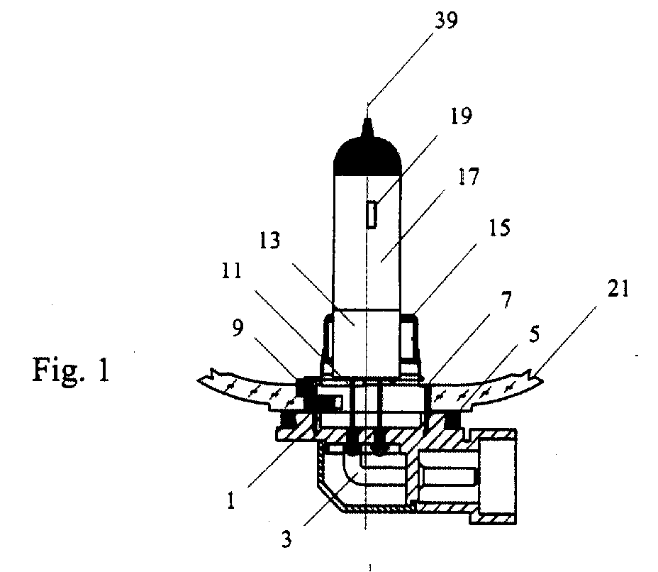
- Fig. 1 is a cross-sectional view of an incandescent lamp and a part of a reflector in which the present invention embodied;
- Fig. 2 is a top view of the of the incandescent lamp according to Fig. 1,
- Fig. 3 is a cross-sectional view of a sleeved optical disc with a leaf-spring and stump shaped locking element taken along a plane A - A of Fig. 4,
- Fig. 4 shows a top view of the sleeved optical disc with the spring and locking element of Fig. 3, and indicates the plane A - A,
- Fig. 5 is a perspective view of the sleeved optical disc shown in Fig. 3 and Fig. 4,
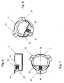
- Fig. 6 is a cross-sectional view of a sleeved optical disc with volute-spring and spherical locking element taken along a plane B - B of Fig. 7,
- Fig. 7 shows a top view of the sleeved optical disc with the spring and locking element of Fig. 6, and indicates the plane B - B,
- Fig. 8 is a perspective view of the sleeved optical disc shown in Fig. 6 and Fig. 7,
- Fig. 9 is a cross-sectional view of a sleeved optical disc with a spring-shaft and a roller shaped locking element taken along a plane C - C of Fig. 10,
- Fig. 10 shows a top view of the sleeved optical disc with the spring-shaft and the roller shaped locking element of Fig. 9, and indicates the plane C - C,
- Fig. 11 is a perspective view of the sleeved optical disc shown in Fig. 9 and Fig. 10,
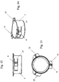
- Fig. 12 is a side view of a sleeved optical disc with a bent leaf-spring cut out as a tongue from the mantle thereof,
- Fig. 13 is a top view of the sleeved optical disc with the tongue shaped leaf-spring of Fig. 12, and
- Fig. 14 is a perspective view of the sleeved optical disc shown in Fig. 12 and Fig. 13.
-
- Referring now to Figs. 1 and 2, a replaceable incandescent lamp is shown in which the present invention is embodied. The lamp is preferably a halogen incandescent lamp such as a H8, H9, H11 type or the like, which is recently used in this area of technology. The incandescent lamp has an
envelope 17 with apinched portion 13 at the one end thereof, afilament 19 and a pair of lead-outwires 11 which supply electric current to thefilament 19 and are included in aplastic base 1. The other ends of the lead-outwires 11 are welded toelectrical terminals 3 integrally mounted in theplastic base 1. Theenvelope 17 of the lamp is held firmly at itspinched portion 13 by ametal support portion 15 which is welded through an intermediary portion to a sleevedoptical disc 7 made of metal and embedded in theplastic base 1. The incandescent lamp is combined with a reflector, the rear end of which is shown around the lamp. The incandescent lamp is placed in the opening of thereflector wall 21 made of glass in a fixed position. - Fixing is provided for by a
locking element 9 which flexibly snaps into an appropriate indent of thereflector wall 21 thus preventing the incandescent lamp from twisting even during vibrations. The incandescent lamp is prevented from moving axially 39 by threeoptical flanges 23 formed on the sleevedoptical disc 7 from one direction, and by a sealing 5 drawn on theplastic base 1 from the other direction. Putting the incandescent lamp into the opening of thereflector wall 21 in the right position is oriented by the threeoptical flanges 23 which fit into the indents formed to a similar shape in the opening of thereflector wall 21. In order to prevent false placement, each of the three 23 optical flanges has a different shape and the same applies for the indents formed in the opening of thereflector wall 21. After putting the incandescent lamp in the reflector axially 39, the lamp is twisted and fixed in the required position. - Figs. 3 - 5 show the sleeved
optical disc 7 of the incandescent lamp with a preferable design of the locking assembly. As it is shown in the figures, the sleevedoptical disc 7 is substantially a cylindrical component open both on the top and at the bottom. The lower part of the sleevedoptical disc 7 is embedded in theplastic base 1, while the threeoptical flanges 23 are formed on its upper part. Theoptical flanges 23 are placed in one plane which is perpendicular to the longitudinal axis of the sleevedoptical disc 7. In the middle of eachoptical flange 23, a radial rib is formed. These ribs with their swelling sides rest upon a reference plane of thereflector wall 21 in the fixed position of the incandescent lamp. Theoptical flanges 23 are aligned along the upper edge of the sleevedoptical disc 7 substantially in the vertices of an equilateral triangle and their shapes meet the applicable standard. In the mantle of the sleevedoptical disc 7, anopening 41 is formed, through which alocking element 9 is slipped. In this embodiment, the lockingelement 9 is stump shaped and its end slipping through theopening 41 is rounded, while its other end is attached to the center of a straight leaf-spring 25. The two ends of the leaf-spring 25 are welded to the internal mantle of the sleevedoptical disc 7. When the incandescent lamp is fixed in the reflector, the rounded external end of thelocking element 9 will be engaged in the indent defined by the wall of the opening of the reflector. The radial force of the leaf-spring 25 provides fixation in the indent mentioned above. Since the leaf-spring 25 need not be bent to a shape, its manufacturing is simple and does not requires additional, complicated and expensive process steps. - In the embodiment of Figs. 6 - 8, the locking assembly comprises a spherical body, preferably a
ball 27 and avolute spring 29, where the diameter of theball 27 is greater than theopening 41 in the mantle of the sleevedoptical disc 7. Thus theball 27 cannot fall through theopening 41, against which theball 27 is pressed by thevolute spring 29 resting on aspring support 31. The two ends of thespring support 31 are welded to the internal surface of the mantle of the sleevedoptical disc 7. Since the spring force in this case is provided by thevolute spring 29, it is not necessary, just advantageous if thespring support 31 is designed as a leaf-spring described above. Since both thevolute spring 29 and theball 27 are commercially available, they can be purchased ready-made, and this simplifies the manufacturing process. - Referring now to Figs. 9 - 11, the locking element is designed as a
roller 35 running on aflexible shaft 33 and the two ends of theflexible shaft 33 are attached to tongues bent inwards from the mantle of the sleevedoptical disc 7. A part of theroller 35 slips through anopening 41 formed in the mantle of the sleevedoptical disc 7. In this embodiment of the invention, springing of the locking element is accomplished by aflexible shaft 33. Theroller 35 has two axial indents on its upper and lower side around the flexible shaft so that this shaft is in contact only with the middle portion of theroller 35. Thus theflexible shaft 33 is capable of flexible deformation which provides the radial force. When twisting the incandescent lamp, theroller 35 is rolling along the wall of the opening of the reflector until it clicks into the locking indent, so that no friction of motion, just rolling occurs on the surface of the reflector glass, which saves the surface thereof. - An embodiment representing the second aspect of the present invention is illustrated by Figs. 12 - 14, where the spring and the locking element are formed from the mantle of the sleeved
optical disc 7 itself. The sleevedoptical disc 7 is manufactured from a pliable metal in several process steps by deep drawing, cutting and bending. The mantle, a lower shoulder and the threeoptical flanges 23 on the upper shoulder, together with the grooves on them are formed in the course of these steps. The spring and the locking element are also formed during these steps by cutting and bending. Atongue 37 is cut out from the mantle of the sleevedoptical disc 7 which forms one piece continuously with the material of the mantle. Thetongue 37 is bent to form a leaf-spring clamped at one end and exerting force along a path substantially perpendicular to the mantle in a direction away from thelongitudinal axis 39. At the free end of thetongue 37, a semicircular bending constitutes the lockingelement 9 to be engaged in the indent of the reflector, while the necessary spring force is provided by the other part of the tongue. In this embodiment representing the best mode of carrying out the invention, no additional component is required as a leaf-spring, since the leaf-spring is provided without a separate mounting procedure in the course of bending and cutting the sleevedoptical disc 7.
Claims (9)
- An incandescent lamp for use in a reflector comprising:an envelope (17) having a longitudinal axis (39), at least one filament (19), and electrical lead-out wires (11);a metal support portion (15) receiving the envelop (17);a sleeved optical disc (7) formed from metal and operatively associated with the metal support portion (15) for positioning the filaments (19) with respect to the reflector in a plane perpendicular to the longitudinal axis (39), the sleeved optical disc (7) having an opening (41) in the mantle thereof;a plastic base (1) anchoring the sleeved optical disc (7) and including the electrical lead-out wires (11);a locking element (9) secured against fall-out and slipped at least partly through the opening (41); anda spring forcing the locking element (9) to move along a path substantially perpendicular to the mantle of the sleeved optical disc (7) in a direction away from the longitudinal axis (39).
- The incandescent lamp of claim 1 in which the spring is secured to the sleeved optical disc (7).
- The incandescent lamp of claim 1 or 2 in which the locking element has a spherical shape and is seated on one end of a volute spring (29); the opening (41) is circular having a diameter smaller than the diameter of the spherical locking element (9); and the other end of the volute spring (29) is seated on a spring holder (31).
- The incandescent lamp of claim 1 or 2 in which the locking element (9) is a roller (35) and is placed around a spring-shaft (33) which is substantially parallel to the longitudinal axis (39) and attached to the mantle to of the sleeved optical disc (7).
- The incandescent lamp of claim 1 or 2 in which the locking element (9) has a stump shape and is secured to a straight leaf-spring (25); the two ends of the leaf-spring (25) are welded to the internal mantle of the sleeved optical disc (7).
- An incandescent lamp for use in a reflector comprising:an envelope (17) having a longitudinal axis (39), at least one filament (19), and electrical lead-out wires (11);a metal support portion (15) receiving the envelop (17);a sleeved optical disc (7) formed from metal and operatively associated with the metal support portion (15) for positioning the filaments (19) with respect to the reflector in a plane perpendicular to the longitudinal axis (39);a plastic base (1) anchoring the sleeved optical disc (7) and including the electrical lead-out wires (11);a tongue (37) cut out from the mantle of the sleeved optical disc (7) and forming one piece continuously with the material of the mantle, the tongue (37) being bent to form a leaf-spring clamped at one end and exerting force along a path substantially perpendicular to the mantle in a direction away from the longitudinal axis (39); anda locking element (9) formed on the leaf-spring.
- The incandescent lamp of claim 6 in which the other end of the leaf-spring is bent to form a locking element (9).
- An incandescent lamp and reflector combination comprising:a reflector having a wall (21) defining an opening;an incandescent lamp including an envelope (17) having a longitudinal axis (39), at least one filament (19), and electrical lead-out wires (11);a metal support portion (15) receiving the envelop (17);a sleeved optical disc (7) formed from metal and operatively associated with the metal support portion (15) for positioning the filaments (19) with respect to the reflector in a plane perpendicular to the longitudinal axis (39), the sleeved optical disc (7) having an opening (41) in the mantle thereof;a plastic base (1) anchoring the sleeved optical disc (7) and including the electrical lead-out wires (11);a locking element (9) secured against fall-out and slipped at least partly through the opening (41);a spring forcing the locking element (9) to move along a path substantially perpendicular to the mantle of the sleeved optical disc (7) in a direction away from the longitudinal axis (39), and the locking element (9) being engaged in an indent formed in the wall (21) of the opening after the incandescent lamp is fixed in the reflector.
- An incandescent lamp and reflector combination comprising:a reflector having a wall (21) defining an opening;an incandescent lamp including an envelope (17) having a longitudinal axis (39), at least one filament (19), and electrical lead-out wires (11);a metal support portion (15) receiving the envelop (17);a sleeved optical disc (7) formed from metal and operatively associated with the metal support portion (15) for positioning the filaments (19) with respect to the reflector in a plane perpendicular to the longitudinal axis (39);a plastic base (1) anchoring the sleeved optical disc (7) and including the electrical lead-out wires (11);a tongue (37) cut out from the mantle of the sleeved optical disc (7) and forming one piece continuously with the material of the mantle, the tongue (37) being bent to form a leaf-spring clamped at one end and exerting force along a path substantially perpendicular to the mantle in a direction away from the longitudinal axis (39);a locking element (9) formed on the leaf-spring, and the locking element (9) being engaged in an indent formed in the wall (21) of the opening after the incandescent lamp is fixed in the reflector.
Applications Claiming Priority (2)
| Application Number | Priority Date | Filing Date | Title |
|---|---|---|---|
| US09/458,230 US6296373B1 (en) | 1999-12-09 | 1999-12-09 | Incandescent lamp for use in a reflector |
| US458230 | 2009-07-06 |
Publications (1)
| Publication Number | Publication Date |
|---|---|
| EP1107279A2 true EP1107279A2 (en) | 2001-06-13 |
Family
ID=23819906
Family Applications (1)
| Application Number | Title | Priority Date | Filing Date |
|---|---|---|---|
| EP00310897A Withdrawn EP1107279A2 (en) | 1999-12-09 | 2000-12-07 | Incandescent lamp for use in a reflector |
Country Status (3)
| Country | Link |
|---|---|
| US (1) | US6296373B1 (en) |
| EP (1) | EP1107279A2 (en) |
| JP (1) | JP2001266619A (en) |
Cited By (2)
| Publication number | Priority date | Publication date | Assignee | Title |
|---|---|---|---|---|
| WO2007096320A1 (en) * | 2006-02-21 | 2007-08-30 | Patent-Treuhand-Gesellschaft für elektrische Glühlampen mbH | Lamp base and lamp comprising said lamp base |
| EP1729326A3 (en) * | 2005-05-24 | 2007-11-14 | Patent-Treuhand-Gesellschaft für elektrische Glühlampen mbH | Lamp base and lamp |
Families Citing this family (3)
| Publication number | Priority date | Publication date | Assignee | Title |
|---|---|---|---|---|
| US7415713B2 (en) * | 2000-01-28 | 2008-08-19 | Iona Technologies, Plc | Method and system for dynamic configuration of interceptors in a client-server environment |
| EP1190439B1 (en) * | 1999-12-17 | 2007-08-08 | Koninklijke Philips Electronics N.V. | Lamp cap, assembly of lamp burner and lamp cap, and method of fastening a lamp |
| DE102004007150A1 (en) * | 2004-02-12 | 2005-08-25 | Patent-Treuhand-Gesellschaft für elektrische Glühlampen mbH | Base for a headlamp and headlamp |
Family Cites Families (3)
| Publication number | Priority date | Publication date | Assignee | Title |
|---|---|---|---|---|
| JPS5347773U (en) * | 1976-09-27 | 1978-04-22 | ||
| US5345372A (en) * | 1992-02-10 | 1994-09-06 | Kabushiki Kaisha T An T | Switchable light fixture |
| CA2215068C (en) | 1996-01-11 | 2004-12-28 | Patent-Treuhand-Gesellschaft Fuer Elektrische Gluehlampen Mbh | Electric lamp with uncemented base |
-
1999
- 1999-12-09 US US09/458,230 patent/US6296373B1/en not_active Expired - Lifetime
-
2000
- 2000-12-07 EP EP00310897A patent/EP1107279A2/en not_active Withdrawn
- 2000-12-08 JP JP2000373650A patent/JP2001266619A/en active Pending
Cited By (3)
| Publication number | Priority date | Publication date | Assignee | Title |
|---|---|---|---|---|
| EP1729326A3 (en) * | 2005-05-24 | 2007-11-14 | Patent-Treuhand-Gesellschaft für elektrische Glühlampen mbH | Lamp base and lamp |
| CN1880842B (en) * | 2005-05-24 | 2010-06-23 | 电灯专利信托有限公司 | Lamp base and lamp |
| WO2007096320A1 (en) * | 2006-02-21 | 2007-08-30 | Patent-Treuhand-Gesellschaft für elektrische Glühlampen mbH | Lamp base and lamp comprising said lamp base |
Also Published As
| Publication number | Publication date |
|---|---|
| JP2001266619A (en) | 2001-09-28 |
| US6296373B1 (en) | 2001-10-02 |
Similar Documents
| Publication | Publication Date | Title |
|---|---|---|
| CN1184661C (en) | Headlight bulb | |
| EP1063671A1 (en) | Lamp and method of producing the same | |
| US6536929B1 (en) | Incandescent lamp for use in a reflector | |
| US6296373B1 (en) | Incandescent lamp for use in a reflector | |
| HU183933B (en) | Electric lamp with lamp base joined up mechanically | |
| US4811178A (en) | Headlight for vehicles | |
| JP3323742B2 (en) | Device for holding linear light guide and method for assembling the same | |
| US4982313A (en) | Light fixture assembly | |
| CN1561530A (en) | spotlight | |
| US3944808A (en) | Lamp mounting assembly | |
| JP2000173321A (en) | Light bulb and lighting device provided with this light bulb | |
| US5651603A (en) | Apparatus for arranging a lamp on a reflector of a vehicle headlight | |
| JP2004200173A (en) | Lighting unit | |
| KR870001470B1 (en) | Lamp assembly | |
| JP3869019B2 (en) | light bulb | |
| GB2355347A (en) | Bayonet-mounted lighting device for a vehicle | |
| US4570210A (en) | Vehicle lamp unit and method for an improved supporting arrangement of its light source | |
| CN1135029A (en) | Miniature discharge lamp tube holder | |
| US4607192A (en) | Pre-focussed incandescent lamps and method of assembling base thereof | |
| NL8501565A (en) | LIGHT SOURCE WITH PARTLY CUT-OFF GLASS BALLOON, PARTICULARLY HALOGEN-LIGHT BULB AND METHOD FOR ATTACHING THE LAMP BODY TO A HEAD OR AN OPTICAL ELEMENT. | |
| JPH0637591Y2 (en) | Wedge base bulb socket | |
| EP0918188A3 (en) | Lighting unit | |
| JP2908908B2 (en) | Spotlight | |
| US5820418A (en) | Electric lamp and method for fixing the light source and the base part of the lamp to each other | |
| US5572090A (en) | Quality lamp and method for making |
Legal Events
| Date | Code | Title | Description |
|---|---|---|---|
| PUAI | Public reference made under article 153(3) epc to a published international application that has entered the european phase |
Free format text: ORIGINAL CODE: 0009012 |
|
| AK | Designated contracting states |
Kind code of ref document: A2 Designated state(s): AT BE CH CY DE DK ES FI FR GB GR IE IT LI LU MC NL PT SE TR |
|
| AX | Request for extension of the european patent |
Free format text: AL;LT;LV;MK;RO;SI |
|
| STAA | Information on the status of an ep patent application or granted ep patent |
Free format text: STATUS: THE APPLICATION HAS BEEN WITHDRAWN |
|
| 18W | Application withdrawn |
Effective date: 20030410 |