EP1107183A2 - Method and computer program for detecting rotation and magnification of images - Google Patents
Method and computer program for detecting rotation and magnification of images Download PDFInfo
- Publication number
- EP1107183A2 EP1107183A2 EP00204083A EP00204083A EP1107183A2 EP 1107183 A2 EP1107183 A2 EP 1107183A2 EP 00204083 A EP00204083 A EP 00204083A EP 00204083 A EP00204083 A EP 00204083A EP 1107183 A2 EP1107183 A2 EP 1107183A2
- Authority
- EP
- European Patent Office
- Prior art keywords
- image
- standard deviation
- modified
- autocorrelation
- modified image
- Prior art date
- Legal status (The legal status is an assumption and is not a legal conclusion. Google has not performed a legal analysis and makes no representation as to the accuracy of the status listed.)
- Granted
Links
Images



Classifications
-
- G—PHYSICS
- G06—COMPUTING OR CALCULATING; COUNTING
- G06T—IMAGE DATA PROCESSING OR GENERATION, IN GENERAL
- G06T1/00—General purpose image data processing
- G06T1/0021—Image watermarking
- G06T1/005—Robust watermarking, e.g. average attack or collusion attack resistant
- G06T1/0064—Geometric transfor invariant watermarking, e.g. affine transform invariant
-
- G—PHYSICS
- G06—COMPUTING OR CALCULATING; COUNTING
- G06T—IMAGE DATA PROCESSING OR GENERATION, IN GENERAL
- G06T2201/00—General purpose image data processing
- G06T2201/005—Image watermarking
- G06T2201/0051—Embedding of the watermark in the spatial domain
-
- G—PHYSICS
- G06—COMPUTING OR CALCULATING; COUNTING
- G06T—IMAGE DATA PROCESSING OR GENERATION, IN GENERAL
- G06T2201/00—General purpose image data processing
- G06T2201/005—Image watermarking
- G06T2201/0065—Extraction of an embedded watermark; Reliable detection
-
- G—PHYSICS
- G06—COMPUTING OR CALCULATING; COUNTING
- G06T—IMAGE DATA PROCESSING OR GENERATION, IN GENERAL
- G06T2201/00—General purpose image data processing
- G06T2201/005—Image watermarking
- G06T2201/0083—Image watermarking whereby only watermarked image required at decoder, e.g. source-based, blind, oblivious
Definitions
- the invention relates generally to the field of image processing, and in particular to methods for detecting when an image has been rotated or resized (magnified).
- an improved method and computer program product for detecting an amount of rotation or magnification in a modified image including the steps of:
- the present invention has the advantage of being able to more easily detect the autocorrelation peaks in an image having large amounts of linear and angular detail.
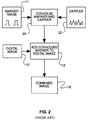
- a digital image 10 is prepared by adding 12 a marker image 11 having a pair of identical features 14 and 16 to produce a combined image 18.
- the identical features 14 and 16 in the marker image 11 are oriented a distance "d" from each other and at an angle " ⁇ " with respect to the vertical in image 10.
- the features 14 and 16 in the marker image 11 are convolved 20 with a carrier image 22 and magnified (or minified) such that their amplitude is low relative to the amplitude of the original image so that the marker image is not visible in the combined image 18.
- the marker image features 14 and 16 are delta functions (one pixel at maximum amplitude) convolved with a random carrier signal 22 having a uniform frequency amplitude and random phase.
- the marker image may contain information such as digital code (such as 0's and 1's ordered in such a way as to effect a message) or text image such as a copyright notice.
- the identical digital code or text images are convolved with the carrier signal 22 as described above and then added to the image 10.
- the angular orientation and/or magnification of the combined image 18 is changed, for example in an optical or digital printing or copy process to produce a modified combined image 24.
- the modified combined image 24 is first preprocessed 25 to have a desired constant local standard deviation.
- a desired standard deviation ⁇ D that is chosen to be relatively low, but not too low (preferably 0.1 to 0.3) and a surrounding area A (preferably over 3x3 to 5x5 pixel regions) for the normalization to be performed 38.
- a local standard deviation ⁇ A is calculated 40.
- the local standard deviation is tested 42 and if the calculated standard deviation is less than the desired standard deviation ⁇ D , it is replaced 44 with a random number generated from a process 46 having the same standard deviation as the desired standard deviation.
- the pixel value is then multiplied 48 by the ratio of the desired standard deviation and the local standard deviation to form a modified pixel value. Finally, all of the pixel values in the modified image are replaced 50 with the modified pixel values.
- the resulting image will have the desired constant local standard deviation ⁇ D . Since the preprocessed image has a constant local standard deviation, the effect on the autocorellation due to the high contrast of the edges and angular features of the image is substantially reduced.
- the preprocessed image is autocorrelated 26.
- the autocorrelation will result in two autocorrelation peaks 28 and 30 corresponding to the centers of the features in the marker image 11.
- the autocorrelation is performed in the frequency domain using Fourier transform techniques.
- the autocorrelation is simply the inverse Fourier transform of the magnitude of the forward Fourier transform.
- the two autocorrelation peaks may, optionally, be further emphasized during the processes of autocorrelation in the frequency domain by weighting the Fourier transform coefficients by the frequency domain representation of a Wiener filter 32 that emphasizes isolated peaks and suppresses smooth regions.
- a Wiener filter 32 An example of a Wiener filter useful for this purpose is illustrated in Figs. 6 and 7.
- the filter 6 is a two dimensional frequency plot having frequency axes f x and fy from zero to the Nyquist frequency N x , N y .
- the filter has the effect of setting to zero the Fourier transform coefficients for frequencies in a region 52 having a radius R centered about zero frequency. For regions outside this radius, the weighting function is a monotonically increasing function as shown by line 54 in Fig. 7.
- a linear ramp may be applied to smooth the transition region at the radius R.
- the autocorrelation peak positions 28 and 30 of the modified image may be measured 34 to obtain the modified distance "d"' and the modified angle "a"' measured with respect to the vertical. If it is of interest to measure rotations greater than 180 degrees, the amplitude of the autocorrelation peaks should be measured.
- the present invention is preferably practiced in an image processing system including a source of digital images, such as a scanner, a computer programmed to process digital images, and an output device such as a thermal or inkjet printer.
- the method of the present invention may be sold as a computer program product including a computer readable storage medium bearing computer code for implementing the steps of the invention.
- Computer readable storage medium may include, for example: magnetic storage media such as a magnetic disc (e.g. a floppy disc) or magnetic tape; optical storage media such as optical disc or optical tape; bar code; solid state electronic storage devices such as random access memory (RAM)or read only memory (ROM); or any other physical device or medium employed to store a computer program.
Landscapes
- Physics & Mathematics (AREA)
- General Physics & Mathematics (AREA)
- Engineering & Computer Science (AREA)
- Theoretical Computer Science (AREA)
- Image Processing (AREA)
- Editing Of Facsimile Originals (AREA)
- Image Analysis (AREA)
- Record Information Processing For Printing (AREA)
- Control Or Security For Electrophotography (AREA)
Abstract
Description
For
Claims (8)
- An improved method for detecting an amount of rotation or magnification in a modified image, of the type including the steps of:a) embedding a marker image having a pair of identical features separated by a distance d and oriented at an angle α in an original image to produce a marked image, the marked image having been rotated and/or magnified to produce the modified image;b) performing an autocorrelation on the modified image to produce a pair of autocorrelation peaks corresponding to the location of the features of the marker image in the modified image; andc) comparing the separation d and orientation α of the autocorrelation peaks with the separation d and orientation α of the features in the marker image to determine the amount of rotation and magnification in the modified image, wherein the improvement comprises the step of:d) preprocessing the modified image to have a constant standard deviation over all local regions in the image.
- The improved method claimed in claim 1, wherein the autocorrelation and filtering operations are performed in the frequency domain.
- The improved method claimed in claim 1, further comprises the step of processing the autocorrelation with a Wiener filter to improve the signal to noise ratio of the autocorrelation peaks.
- The improved method claimed in claim 1, wherein the preprocessing step comprises the steps of:a) specifying a desired standard deviation;b) for each pixel within the modified image,i) calculating a local standard deviation, and if calculated standard deviation is less than the desired standard deviation, replacing it with a random number generated from a process having the same standard deviation as the desired standard deviation,ii) multiplying the pixel value by the ratio of the desired standard deviation and the local standard deviation to form a modified pixel value; andc) replacing all of the pixel values in the modified image with the modified pixel values.
- An improved computer program product, including a computer readable storage medium having a computer program stored thereon for detecting an amount of rotation or magnification in a modified image, for performing the steps of:a) embedding a marker image having a pair of identical features separated by a distance d and oriented at an angle a in an original image to produce a marked image, the marked image having been rotated and/or magnified to produce the modified image;b) performing an autocorrelation on the modified image to produce a pair of autocorrelation peaks corresponding to the location of the features of the marker image in the modified image; andc) comparing the separation d' and orientation a' of the autocorrelation peaks with the separation d and orientation a of the features in the marker image to determine the amount of rotation and magnification in the modified image, wherein the improvement comprises the step of preprocessing the modified image to have a constant standard deviation over all local regions in the image..
- The improved computer program product claimed in claim 5, wherein the autocorrelation and filtering operations are performed in the frequency domain.
- The computer program product method claimed in claim 6, further comprising the step of processing the autocorrelation with a Wiener filter to improve the signal to noise ratio of the autocorrelation peaks.
- The improved computer program product claimed in claim 5, wherein the preprocessing step comprises the steps of:a) specifying a desired standard deviation;b) for each pixel within the modified image,i) calculating a local standard deviation, and if calculated standard deviation is less than the desired standard deviation, replacing it with a random number generated from a process having the same standard deviation as the desired standard deviation,ii) multiplying the pixel value by the ratio of the desired standard deviation and the local standard deviation to form a modified pixel value; andc) replacing all of the pixel values in the modified image with the modified pixel values.
Applications Claiming Priority (2)
| Application Number | Priority Date | Filing Date | Title |
|---|---|---|---|
| US09/452,415 US6711303B1 (en) | 1999-12-01 | 1999-12-01 | Method and computer program for detecting rotation and magnification of images |
| US452415 | 1999-12-01 |
Publications (3)
| Publication Number | Publication Date |
|---|---|
| EP1107183A2 true EP1107183A2 (en) | 2001-06-13 |
| EP1107183A3 EP1107183A3 (en) | 2002-10-02 |
| EP1107183B1 EP1107183B1 (en) | 2004-02-18 |
Family
ID=23796366
Family Applications (1)
| Application Number | Title | Priority Date | Filing Date |
|---|---|---|---|
| EP00204083A Expired - Lifetime EP1107183B1 (en) | 1999-12-01 | 2000-11-20 | Method and computer program for detecting rotation and magnification of images |
Country Status (4)
| Country | Link |
|---|---|
| US (1) | US6711303B1 (en) |
| EP (1) | EP1107183B1 (en) |
| JP (1) | JP2001209806A (en) |
| DE (1) | DE60008346T2 (en) |
Families Citing this family (6)
| Publication number | Priority date | Publication date | Assignee | Title |
|---|---|---|---|---|
| US6424725B1 (en) * | 1996-05-16 | 2002-07-23 | Digimarc Corporation | Determining transformations of media signals with embedded code signals |
| JP2003169205A (en) | 2001-11-30 | 2003-06-13 | Toshiba Corp | Digital watermark embedding method and device, and digital watermark detection method and device |
| US7593597B2 (en) * | 2003-08-06 | 2009-09-22 | Eastman Kodak Company | Alignment of lens array images using autocorrelation |
| US20050271300A1 (en) * | 2004-06-02 | 2005-12-08 | Pina Robert K | Image registration system and method |
| US7835587B2 (en) * | 2006-12-18 | 2010-11-16 | Intel Corporation | Method and apparatus for local standard deviation based histogram equalization for adaptive contrast enhancement |
| JP5529568B2 (en) * | 2010-02-05 | 2014-06-25 | キヤノン株式会社 | Image processing apparatus, imaging apparatus, control method, and program |
Family Cites Families (18)
| Publication number | Priority date | Publication date | Assignee | Title |
|---|---|---|---|---|
| US3749919A (en) * | 1969-09-19 | 1973-07-31 | United Aircraft Corp | Image correlating device comprising plural photoconductive layers |
| US4084255A (en) * | 1976-11-02 | 1978-04-11 | The United States Of America As Represented By The Secretary Of The Navy | Positional, rotational and scale invariant optical correlation method and apparatus |
| US4571635A (en) * | 1984-02-17 | 1986-02-18 | Minnesota Mining And Manufacturing Company | Method of image enhancement by raster scanning |
| EP0440786A1 (en) * | 1989-08-28 | 1991-08-14 | Eastman Kodak Company | A computer based digital image noise reduction method based on overlapping planar approximation |
| US5185815A (en) * | 1991-11-04 | 1993-02-09 | Grumman Aerospace Corporation | Multiple target correlator system |
| DE69530169T2 (en) * | 1994-12-28 | 2003-11-13 | Fuji Photo Film Co., Ltd. | Method of producing color proofs |
| US5822458A (en) * | 1995-02-06 | 1998-10-13 | The Regents Of The University Of California | Precomputing and encoding compressed image enhancement instructions |
| US5852678A (en) * | 1996-05-30 | 1998-12-22 | Xerox Corporation | Detection and rendering of text in tinted areas |
| IL119221A0 (en) * | 1996-09-08 | 1996-12-05 | Scitex Corp Ltd | Apparatus and method for retouching a digital representation of a color image |
| US5835639A (en) | 1996-12-18 | 1998-11-10 | Eastman Kodak Company | Method for detecting rotation and magnification in images |
| US6219462B1 (en) * | 1997-05-09 | 2001-04-17 | Sarnoff Corporation | Method and apparatus for performing global image alignment using any local match measure |
| US5982915A (en) * | 1997-07-25 | 1999-11-09 | Arch Development Corporation | Method of detecting interval changes in chest radiographs utilizing temporal subtraction combined with automated initial matching of blurred low resolution images |
| WO1999010832A1 (en) * | 1997-08-27 | 1999-03-04 | Plettac Electronic Security Gmbh | Method for localizing objects in still images used to localize faces |
| CN1143532C (en) | 1997-09-02 | 2004-03-24 | 皇家菲利浦电子有限公司 | Method and arrangement for detecting watermark |
| US5887084A (en) * | 1997-11-07 | 1999-03-23 | Polaroid Corporation | Structuring a digital image into a DCT pyramid image representation |
| US6091243A (en) * | 1997-11-13 | 2000-07-18 | The University Of British Columbia | Water-fat imaging with direct phase encoding (DPE) |
| US6268611B1 (en) * | 1997-12-18 | 2001-07-31 | Cellavision Ab | Feature-free registration of dissimilar images using a robust similarity metric |
| US6385329B1 (en) * | 2000-02-14 | 2002-05-07 | Digimarc Corporation | Wavelet domain watermarks |
-
1999
- 1999-12-01 US US09/452,415 patent/US6711303B1/en not_active Expired - Fee Related
-
2000
- 2000-11-20 EP EP00204083A patent/EP1107183B1/en not_active Expired - Lifetime
- 2000-11-20 DE DE60008346T patent/DE60008346T2/en not_active Withdrawn - After Issue
- 2000-11-29 JP JP2000363368A patent/JP2001209806A/en active Pending
Also Published As
| Publication number | Publication date |
|---|---|
| EP1107183B1 (en) | 2004-02-18 |
| US6711303B1 (en) | 2004-03-23 |
| DE60008346D1 (en) | 2004-03-25 |
| EP1107183A3 (en) | 2002-10-02 |
| JP2001209806A (en) | 2001-08-03 |
| DE60008346T2 (en) | 2004-12-30 |
Similar Documents
| Publication | Publication Date | Title |
|---|---|---|
| US5835639A (en) | Method for detecting rotation and magnification in images | |
| Barni et al. | A DCT-domain system for robust image watermarking | |
| Lokhande et al. | Identification of parameters and restoration of motion blurred images | |
| US6754365B1 (en) | Detecting embedded information in images | |
| US6788801B2 (en) | Cocktail watermarking on images | |
| Alghoniemy et al. | Geometric distortion correction through image normalization | |
| Sun et al. | Skew and slant correction for document images using gradient direction | |
| EP1202552A2 (en) | Method for generating and detecting marks | |
| Solachidis et al. | Fourier descriptors watermarking of vector graphics images | |
| US6795565B2 (en) | Method to detect watermark resistant to resizing and translation | |
| US20030086587A1 (en) | Watermark detection | |
| AU2003237373B2 (en) | Method and apparatus to detect watermark that are resistant to resizing, rotation and translation | |
| Johnson et al. | Recovery of watermarks from distorted images | |
| US6567532B1 (en) | Method and computer program for extracting an embedded message from a digital image | |
| Munib et al. | Robust image watermarking technique using triangular regions and Zernike moments for quantization based embedding | |
| EP1107183B1 (en) | Method and computer program for detecting rotation and magnification of images | |
| CN112241929A (en) | Watermark embedding and watermark detection method, device and electronic device | |
| CN111986124A (en) | Filling method and device for missing pixels of depth image | |
| WO2004090811A2 (en) | Method of detecting watermarks | |
| KR101980864B1 (en) | Watermark inserting apparatus, watermark detecting apparatus and the method thereof | |
| Tao et al. | Robust digital image watermarking in curvelet domain | |
| CN103020886B (en) | Digital scanning map watermarking method based on linear characteristic | |
| CN100361140C (en) | A Method for Detecting Rotation Angle and Scaling Ratio of Scanned Document Image | |
| Chotikakamthorn et al. | Ring-shaped digital watermark for rotated and scaled images using random-phase sinusoidal function | |
| JP3878495B2 (en) | Digital watermark method, digital watermark embedding method, and digital watermark detection method |
Legal Events
| Date | Code | Title | Description |
|---|---|---|---|
| PUAI | Public reference made under article 153(3) epc to a published international application that has entered the european phase |
Free format text: ORIGINAL CODE: 0009012 |
|
| AK | Designated contracting states |
Kind code of ref document: A2 Designated state(s): AT BE CH CY DE DK ES FI FR GB GR IE IT LI LU MC NL PT SE TR |
|
| AX | Request for extension of the european patent |
Free format text: AL;LT;LV;MK;RO;SI |
|
| PUAL | Search report despatched |
Free format text: ORIGINAL CODE: 0009013 |
|
| RIC1 | Information provided on ipc code assigned before grant |
Free format text: 7G 06T 7/00 A, 7G 06T 1/00 B |
|
| AK | Designated contracting states |
Kind code of ref document: A3 Designated state(s): AT BE CH CY DE DK ES FI FR GB GR IE IT LI LU MC NL PT SE TR |
|
| AX | Request for extension of the european patent |
Free format text: AL;LT;LV;MK;RO;SI |
|
| 17P | Request for examination filed |
Effective date: 20030311 |
|
| AKX | Designation fees paid |
Designated state(s): DE FR GB |
|
| GRAP | Despatch of communication of intention to grant a patent |
Free format text: ORIGINAL CODE: EPIDOSNIGR1 |
|
| GRAS | Grant fee paid |
Free format text: ORIGINAL CODE: EPIDOSNIGR3 |
|
| GRAA | (expected) grant |
Free format text: ORIGINAL CODE: 0009210 |
|
| AK | Designated contracting states |
Kind code of ref document: B1 Designated state(s): DE FR GB |
|
| REG | Reference to a national code |
Ref country code: GB Ref legal event code: FG4D |
|
| REG | Reference to a national code |
Ref country code: IE Ref legal event code: FG4D |
|
| REF | Corresponds to: |
Ref document number: 60008346 Country of ref document: DE Date of ref document: 20040325 Kind code of ref document: P |
|
| ET | Fr: translation filed | ||
| PLBE | No opposition filed within time limit |
Free format text: ORIGINAL CODE: 0009261 |
|
| STAA | Information on the status of an ep patent application or granted ep patent |
Free format text: STATUS: NO OPPOSITION FILED WITHIN TIME LIMIT |
|
| 26N | No opposition filed |
Effective date: 20041119 |
|
| PGFP | Annual fee paid to national office [announced via postgrant information from national office to epo] |
Ref country code: GB Payment date: 20051004 Year of fee payment: 6 |
|
| PGFP | Annual fee paid to national office [announced via postgrant information from national office to epo] |
Ref country code: FR Payment date: 20051104 Year of fee payment: 6 |
|
| PGFP | Annual fee paid to national office [announced via postgrant information from national office to epo] |
Ref country code: DE Payment date: 20051130 Year of fee payment: 6 |
|
| PG25 | Lapsed in a contracting state [announced via postgrant information from national office to epo] |
Ref country code: DE Free format text: LAPSE BECAUSE OF THE APPLICANT RENOUNCES Effective date: 20060221 |
|
| GBPC | Gb: european patent ceased through non-payment of renewal fee |
Effective date: 20061120 |
|
| REG | Reference to a national code |
Ref country code: FR Ref legal event code: ST Effective date: 20070731 |
|
| PG25 | Lapsed in a contracting state [announced via postgrant information from national office to epo] |
Ref country code: GB Free format text: LAPSE BECAUSE OF NON-PAYMENT OF DUE FEES Effective date: 20061120 |
|
| PG25 | Lapsed in a contracting state [announced via postgrant information from national office to epo] |
Ref country code: FR Free format text: LAPSE BECAUSE OF NON-PAYMENT OF DUE FEES Effective date: 20061130 |