EP1107071A2 - Image forming apparatus - Google Patents
Image forming apparatus Download PDFInfo
- Publication number
- EP1107071A2 EP1107071A2 EP00126118A EP00126118A EP1107071A2 EP 1107071 A2 EP1107071 A2 EP 1107071A2 EP 00126118 A EP00126118 A EP 00126118A EP 00126118 A EP00126118 A EP 00126118A EP 1107071 A2 EP1107071 A2 EP 1107071A2
- Authority
- EP
- European Patent Office
- Prior art keywords
- image
- image forming
- speed
- toner
- forming apparatus
- Prior art date
- Legal status (The legal status is an assumption and is not a legal conclusion. Google has not performed a legal analysis and makes no representation as to the accuracy of the status listed.)
- Granted
Links
- 239000000463 material Substances 0.000 claims abstract description 23
- 238000012546 transfer Methods 0.000 claims description 27
- 230000015572 biosynthetic process Effects 0.000 description 15
- 238000000034 method Methods 0.000 description 12
- 238000012545 processing Methods 0.000 description 12
- 239000003086 colorant Substances 0.000 description 5
- 238000013507 mapping Methods 0.000 description 4
- 238000010276 construction Methods 0.000 description 3
- 230000003247 decreasing effect Effects 0.000 description 3
- 238000010586 diagram Methods 0.000 description 3
- 230000002093 peripheral effect Effects 0.000 description 3
- 238000006243 chemical reaction Methods 0.000 description 1
- 230000002542 deteriorative effect Effects 0.000 description 1
- 238000011161 development Methods 0.000 description 1
- 230000000694 effects Effects 0.000 description 1
Images



Classifications
-
- G—PHYSICS
- G03—PHOTOGRAPHY; CINEMATOGRAPHY; ANALOGOUS TECHNIQUES USING WAVES OTHER THAN OPTICAL WAVES; ELECTROGRAPHY; HOLOGRAPHY
- G03G—ELECTROGRAPHY; ELECTROPHOTOGRAPHY; MAGNETOGRAPHY
- G03G15/00—Apparatus for electrographic processes using a charge pattern
- G03G15/50—Machine control of apparatus for electrographic processes using a charge pattern, e.g. regulating differents parts of the machine, multimode copiers, microprocessor control
- G03G15/5008—Driving control for rotary photosensitive medium, e.g. speed control, stop position control
-
- G—PHYSICS
- G03—PHOTOGRAPHY; CINEMATOGRAPHY; ANALOGOUS TECHNIQUES USING WAVES OTHER THAN OPTICAL WAVES; ELECTROGRAPHY; HOLOGRAPHY
- G03G—ELECTROGRAPHY; ELECTROPHOTOGRAPHY; MAGNETOGRAPHY
- G03G15/00—Apparatus for electrographic processes using a charge pattern
- G03G15/02—Apparatus for electrographic processes using a charge pattern for laying down a uniform charge, e.g. for sensitising; Corona discharge devices
- G03G15/0266—Arrangements for controlling the amount of charge
-
- G—PHYSICS
- G03—PHOTOGRAPHY; CINEMATOGRAPHY; ANALOGOUS TECHNIQUES USING WAVES OTHER THAN OPTICAL WAVES; ELECTROGRAPHY; HOLOGRAPHY
- G03G—ELECTROGRAPHY; ELECTROPHOTOGRAPHY; MAGNETOGRAPHY
- G03G15/00—Apparatus for electrographic processes using a charge pattern
- G03G15/06—Apparatus for electrographic processes using a charge pattern for developing
- G03G15/065—Arrangements for controlling the potential of the developing electrode
-
- G—PHYSICS
- G03—PHOTOGRAPHY; CINEMATOGRAPHY; ANALOGOUS TECHNIQUES USING WAVES OTHER THAN OPTICAL WAVES; ELECTROGRAPHY; HOLOGRAPHY
- G03G—ELECTROGRAPHY; ELECTROPHOTOGRAPHY; MAGNETOGRAPHY
- G03G2215/00—Apparatus for electrophotographic processes
- G03G2215/00362—Apparatus for electrophotographic processes relating to the copy medium handling
- G03G2215/00919—Special copy medium handling apparatus
- G03G2215/00949—Copy material feeding speed switched according to current mode of the apparatus, e.g. colour mode
-
- G—PHYSICS
- G03—PHOTOGRAPHY; CINEMATOGRAPHY; ANALOGOUS TECHNIQUES USING WAVES OTHER THAN OPTICAL WAVES; ELECTROGRAPHY; HOLOGRAPHY
- G03G—ELECTROGRAPHY; ELECTROPHOTOGRAPHY; MAGNETOGRAPHY
- G03G2215/00—Apparatus for electrophotographic processes
- G03G2215/01—Apparatus for electrophotographic processes for producing multicoloured copies
- G03G2215/0103—Plural electrographic recording members
- G03G2215/0119—Linear arrangement adjacent plural transfer points
-
- G—PHYSICS
- G03—PHOTOGRAPHY; CINEMATOGRAPHY; ANALOGOUS TECHNIQUES USING WAVES OTHER THAN OPTICAL WAVES; ELECTROGRAPHY; HOLOGRAPHY
- G03G—ELECTROGRAPHY; ELECTROPHOTOGRAPHY; MAGNETOGRAPHY
- G03G2215/00—Apparatus for electrophotographic processes
- G03G2215/02—Arrangements for laying down a uniform charge
- G03G2215/021—Arrangements for laying down a uniform charge by contact, friction or induction
Definitions
- the present invention relates to an image forming apparatus such as an electrophotographic apparatus.
- four image bearing members are provided so that, by effecting image formation (charging, exposure and development) independently for each color (referred to as "four-drum system” hereinafter), the image forming speed is increased by four times.
- the fixing speed is decreased.
- the fixing speed can be changed while keeping rotational speeds of the image bearing members (photosensitive members) constant.
- the present invention aims to eliminate the above-mentioned conventional drawbacks, and an object of the present invention is to provide an image forming apparatus capable of achieving high speed image formation and high image quality.
- Fig. 1 shows a schematic construction of an image forming apparatus according to a first embodiment of the present invention.
- a full-color image forming apparatus 20 using a four-drum system includes four image forming stations 20Y, 20M, 20C and 20K. Further, these image forming stations 20Y, 20M, 20C and 20K include photosensitive drums 1Y, 1M, 1C, 1K as image bearing members rotated at a predetermined peripheral speed (process speed) in directions shown by the arrows, charging rollers 2Y, 2M, 2C, 2K for uniformly charging surfaces of the photosensitive drums 1Y, 1M, 1C, 1K with predetermined polarity and potential, LEDs 3Y, 3M, 3C, 3K as exposing means for forming electrostatic latent images on the photosensitive drums by exposure, and developing devices 4Y, 4M, 4C, 4K for developing the electrostatic latent image formed on the photosensitive drums by the exposure of the LEDs 3Y, 3M, 3C, 3K with Y (yellow) toner, M (magenta) toner, C (cyan) toner and B (
- a transfer convey belt 12 are mounted around a drive roller 9 and a driven roller 91 and is rotated at a predetermined peripheral speed in a direction shown by the arrow by the drive roller 9.
- Transfer chargers 8Y, 8M, 8C, 8K and the photosensitive drums 1Y, 1M, 1C, 1K define transfer nips therebetween.
- Transfer materials 13 as recording materials contained in a cassette 14 are fed out by means of a conveying roller 15 and the like.
- toner images formed and born on the photosensitive drums 1Y, 1M, 1C, 1K are successively transferred onto the transfer material 13 by transfer biases applied from bias power sources (not shown) to the transfer chargers 8Y, 8M, 8C, 8K.
- an image reading portion 31 in which light from a light source 32 is illuminated onto an original (not shown) rested on an upper surface of the image reading portion, and an image of the original is read by inputting light reflected from the original onto an CCD 34 through a mirror 33.
- the reading light inputted to the CCD 34 is subjected to image processing by means of an image processing portions which will be described later and then is inputted to the LEDs 3Y, 3M, 3C, 3K.
- the LEDs 3Y, 3M, 3C, 3K serve to effect exposure on the basis of the inputted signals.
- an image signal from a computer may be inputted to the LEDs 3Y, 3M, 3C, 3K.
- the LEDs 3Y, 3M, 3C, 3K perform the exposure on the basis of such input signals.
- the image formation first of all, as a charging step, the surface of the photosensitive drum 1Y in the first image forming station 20Y is uniformly charged by the charging roller 2Y with the predetermined polarity and potential while the photosensitive drum 1Y is being rotated. Then, as an exposing step, an electrostatic latent image corresponding to a first color (yellow) component of a target color image is formed on the surface of the photosensitive drum 1Y by the exposure of the LED 3Y. Incidentally, for each pixel, a reproduction gradation number is binary values.
- the electrostatic latent image is developed by the first developing device (yellow developing device) 4Y to form a first color yellow toner image.
- the first color yellow toner image formed and born on the photosensitive drum 1Y is electrostatically transferred onto the transfer material 13 by the transfer bias applied from the bias power source to the transfer charger 8Y while the transfer material 13 fed from the sheet feeding cassette 14 at the predetermined timing and born on the transfer convey belt 12 (rotated at the predetermined peripheral speed in the direction shown by the arrow by the drive roller 9) is being passed through the transfer nip between the transfer convey belt 12 and the photosensitive drum 1Y.
- image forming processes similar to that in the first image forming station 20Y are effected at predetermined timings. In this way, yellow, magenta, cyan and black toner images are successively transferred onto the transfer material 13 in a superimposed fashion, thereby obtaining the target full-color image at a high speed.
- the transfer material 13 to which the toner images were transferred is separated from the transfer convey belt 12 and then is introduced into a fixing device 10 of heat roller type, where the toner images are thermally fixed to the transfer material 13.
- the image forming apparatus 20 is provided with a high speed mode and a standard mode as image forming modes.
- an image forming speed in the high speed mode is 150 mm/sec (a fixing speed is substantially the same as this speed)
- an image forming speed in the standard mode is 100 mm/sec (a fixing speed is substantially the same as this speed).
- an image outputting speed is 30 ppm (print per minute) in the high speed mode and 20 ppm in the standard mode.
- the image forming speed is slower than that in the high speed mode, image quality is higher than that in the high speed mode.
- the kind of the transfer material used in the standard mode is the same as that used in the high speed mode, and, in the illustrated embodiment, a plain paper is used. Selection between the standard mode and the high speed mode is effected by the user by using an operating portion of the apparatus 20.
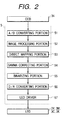
- Fig. 2 is a block diagram of the image forming apparatus. Now, the image formation performed when the standard mode is selected will be explained with reference to Fig. 2.
- RGB signals inputted from the image reading portion 31 (CCD 34) or the computer are firstly A/Dconverted in an A/D converting portion 51 of an image processing device 5 and are subjected to predetermined processing in an image processing portion 52. Thereafter, the signals are converted into YMCK signals in a direct mapping portion 53.
- a printer gamma property is optimized by effecting gamma conversion processing in a gamma correcting portion 54
- 8-bit YMCK signals are converted into 1-bit in a binarizing portion 55.
- the YMCK signals converted to 1-bit are D/A-converted in a D/A converting portion 56 and then are sent to LED drivers 57 by which the signals are outputted to the LEDs 3Y, 3M, 3C, 3K.
- a maximum toner carrying amount of ffh per one color during image formation (single color image formation) in the standard mode is 0.5 mg/cm 2 , and, density of each color in this case becomes 1.60.
- the processing is effected in the direct mapping portion 53 so that total toner carrying amounts in second order (two color superimposition), third order (three color superimposition) and fourth order (four color superimposition) colors become 1.4 mg/cm 2 at the maximum.
- the toner amount by which adequate fixing ability can be obtained is a value determined by 1.4 mg/cm 2 and is an amount capable of providing sufficient color reproduction in the standard mode.
- the density i.e., maximum toner carrying amount (maximum toner amount per unit area for developing the electrostatic latent image) is reduced by selecting developing contrast in the high speed mode to be smaller than that in the standard mode to obtain high image quality to some extent.
- a controlling device 6 for setting an image formation process condition in accordance with the image forming mode selected so that, when the high speed mode is selected as the image forming mode, the image processing device 5 is controlled by the controlling device 6 to set the process condition for reducing the maximum toner carrying amount per unit area.
- the high speed mode by reducing the maximum toner carrying amount per unit area in comparison with the standard mode in this way, high speed image output can be achieved while always maintaining good fixing ability.
- the controlling device 6 judges whether the image forming mode is the standard mode or the high speed mode (step S100). If the standard mode is selected as the image forming mode ("Y" in the step S100), the maximum carrying amount after the transferring to the transfer material is selected to 1.4 mg/cm 2 (step S101).
- the image signal providing the maximum density for each color 8-bit input is ffh (hexa-decimal scale)
- the maximum toner carrying amount of ffh per one color during image formation is 0.5 mg/cm 2 , and, the density of each color in this case becomes 1.60.
- primary charging potential Vd of the photosensitive drum is set to -500 V (step S102) by controlling the voltage applied to the charging roller and a DC component value Vdc of the developing bias to the developing device is set to -350 V (step S103).
- step S104 the standard mode image is formed.
- the control is performed so that the maximum toner carrying amount of ffh per one color during image formation (single color image formation) becomes is 0.4 mg/cm 2 , and the maximum toner carrying amounts in second order (two color superimposition), third order (three color superimposition) and fourth order (four color superimposition) colors become 1.0 mg/cm 2 (step S110).
- the primary charging potential Vd is set to -450 V (step S111) and the DC component value Vdc of the developing bias is set to -300 V (step S112).
- the potential Vff of a portion exposed with ffh is -150 V and the developing contrast (Vff - Vdc) is 150 V.
- the developing contrast (Vff-Vdc) 150 V
- the density can be reduced totally without changing the configuration of the gamma property of the printer with respect to the standard mode.
- the processing is performed in the direct mapping portion so that the maximum toner carrying amounts in second order, third order and fourth order colors become 1.0 mg/cm 2 .
- the high speed image output can be achieved while always maintaining the good fixing ability.
- good color reproductivity can be provided, with the result that both the high speed mode and the standard mode capable of providing the good color reproduction can be compatible in the single image forming apparatus.
- the present invention is not limited to such an example, but, the maximum toner carrying amounts may be changed without changing the contrast.
- Fig. 5 is a flow chart for explaining a controlling operation of an image forming apparatus according to a second embodiment of the present invention in which maximum toner carrying amounts are changed without changing contrast.
- the controlling device judges whether the image forming mode is the standard mode or the high speed mode (step S200). If the standard mode is selected as the image forming mode ("Y" in the step S200), the maximum carrying amount is selected to 1.4 mg/cm 2 (step S201). In this case, when it is assumed that the image signal providing the maximum density for each color 8-bit input is ffh (hexa-decimal scale), the maximum toner carrying amount of ffh per one color during image formation is 0.5 mg/cm 2 , and, the density of each color in this case becomes 1.60.
- the toner amount by which adequate fixing ability can be obtained is a value determined by 1.4 mg/cm 2 and is an amount capable of providing sufficient color reproduction in the standard mode.
- primary charging potential Vd of the photosensitive drum is set to -150 V and a DC component value Vdc of the developing bias to the developing device is set to -350 V.
- potential Vff of a portion exposed with ffh is set to-150 V.
- developing contrast (Vff - Vdc) is 200 V
- Vback (Vdc - Vd) is -150 V.
- these values are values obtained under an environment (temperature of 24°C, humidity of 60%) and are controlled to optimum values by the controlling device on the basis of temperature/humidity data detected by an environment sensor (not shown) so that the carrying amount for each color becomes 0.5 mg/cm 2 .
- the process condition is set to be the same as that in the standard mode, and the processing effected by the direct mapping portion is changed. That is to say, the carrying amount of ffh per one color is not changed, and the maximum toner carrying amounts in second order, third order and fourth order colors are set to 1.0 mg/cm 2 (step S203).
- the maximum toner carrying amounts in second order, third order and fourth order colors without changing the carrying amount of ffh per one color by the image processing in this way, the maximum toner carrying amounts can be changed without changing the contrast, with the result that the toner carrying amount can be set in accordance with the process speed so that the satisfactory fixing ability can be provided in any process speed.
- the present invention when the image formation is performed at the high image forming speed, high speed and high image quality requirements of the image formation can be achieved by reducing the maximum toner amount per unit area in comparison with the low speed image formation.
- the present invention provides an image forming apparatus which has image forming device for forming a toner image on a recording material, fixing device for fixing the toner image on the recording material, and wherein an image forming speed at which the toner image is formed by the image forming device being adapted to be selected to a first speed or a second speed greater than the first speed, control device for controlling so that, when the second speed is selected, a maximum toner amount per unit area of the toner image becomes smaller than that when the first speed is selected.
Landscapes
- Physics & Mathematics (AREA)
- General Physics & Mathematics (AREA)
- Engineering & Computer Science (AREA)
- Plasma & Fusion (AREA)
- Microelectronics & Electronic Packaging (AREA)
- Color Electrophotography (AREA)
- Fixing For Electrophotography (AREA)
- Control Or Security For Electrophotography (AREA)
- Developing For Electrophotography (AREA)
- Exposure Or Original Feeding In Electrophotography (AREA)
- Electrostatic Charge, Transfer And Separation In Electrography (AREA)
Abstract
Description
Claims (11)
- An image forming apparatus comprising:image forming means for forming a toner image on a recording material;fixing means for fixing the toner image on the recording material; andwherein an image forming speed at which the toner image is formed by said image forming means being adapted to be selected to a first speed or a second speed greater than the first speed,control means for controlling so that, when the second speed is selected, a maximum toner amount per unit area of the toner image becomes smaller than that when the first speed is selected.
- An image forming apparatus according to claim 1, wherein said image forming means includes an image bearing member, means for forming the toner image on said image bearing member, and transfer means for transferring the toner image from said image bearing member to the recording material, and wherein, when the second speed is selected, the maximum toner amount per unit area of the toner image formed on said image bearing member becomes smaller than that when the first speed is selected.
- An image forming apparatus according to claim 1, wherein said image forming means includes an image bearing member, electrostatic latent image forming means for forming an electrostatic latent image on said image bearing member, developing means for developing the electrostatic latent image with toner to form the toner image on said image bearing member, and transfer means for transferring the toner image from said image bearing member to the recording material, and wherein, when the second speed is selected, the maximum toner amount per unit area of the toner image developed by said developing means becomes smaller than that when the first speed is selected.
- An image forming apparatus according to claim 3, wherein the maximum toner amount is changed by changing a developing condition of said developing means.
- An image forming apparatus according to claim 3, wherein said electrostatic latent image forming means includes charging means for charging said image bearing member, and wherein the maximum toner amount is changed by changing a charging condition of said charging means.
- An image forming apparatus according to claim 4, wherein said electrostatic latent image forming means includes charging means for charging said image bearing member, and wherein the maximum toner amount is changed by changing a charging condition of said charging means.
- An image forming apparatus according to claim 3, wherein said electrostatic latent image forming means includes charging means for charging said image bearing member, and exposing means for image-exposing said image bearing means charged by said charging means based on an image signal, and further wherein the maximum toner amount is changed by changing the image signal.
- An image forming apparatus according to claim 1, wherein said fixing means include a fixing roller.
- An image forming apparatus according to claim 1, wherein the toner image is formed from a plurality of color toners superimposed.
- An image forming apparatus according to claim 1, wherein kind of the recording material to be used is the same regardless of selection between the first speed and the second speed.
- An image forming apparatus according to claim 1, wherein the recording material to be used is a plain paper regardless of selection between the first speed and the second speed.
Applications Claiming Priority (2)
| Application Number | Priority Date | Filing Date | Title |
|---|---|---|---|
| JP34125499A JP2001154538A (en) | 1999-11-30 | 1999-11-30 | Image forming device |
| JP34125499 | 1999-11-30 |
Publications (3)
| Publication Number | Publication Date |
|---|---|
| EP1107071A2 true EP1107071A2 (en) | 2001-06-13 |
| EP1107071A3 EP1107071A3 (en) | 2003-12-03 |
| EP1107071B1 EP1107071B1 (en) | 2008-08-13 |
Family
ID=18344619
Family Applications (1)
| Application Number | Title | Priority Date | Filing Date |
|---|---|---|---|
| EP00126118A Expired - Lifetime EP1107071B1 (en) | 1999-11-30 | 2000-11-29 | Image forming apparatus |
Country Status (4)
| Country | Link |
|---|---|
| US (1) | US6393229B1 (en) |
| EP (1) | EP1107071B1 (en) |
| JP (1) | JP2001154538A (en) |
| DE (1) | DE60039839D1 (en) |
Cited By (1)
| Publication number | Priority date | Publication date | Assignee | Title |
|---|---|---|---|---|
| EP1355203A2 (en) | 2002-04-16 | 2003-10-22 | Canon Kabushiki Kaisha | Image forming apparatus |
Families Citing this family (6)
| Publication number | Priority date | Publication date | Assignee | Title |
|---|---|---|---|---|
| JP2005049520A (en) * | 2003-07-31 | 2005-02-24 | Canon Inc | Image forming apparatus |
| US7110686B2 (en) * | 2003-07-31 | 2006-09-19 | Canon Kabushiki Kaisha | Image forming apparatus capable of changing usage ratio among multiple toners |
| JP5585870B2 (en) * | 2010-08-20 | 2014-09-10 | 株式会社リコー | Image forming apparatus |
| US8886107B2 (en) | 2011-09-30 | 2014-11-11 | Canon Kabushiki Kaisha | Image processing apparatus, image processing method, and computer-readable medium |
| JP2013076952A (en) * | 2011-09-30 | 2013-04-25 | Canon Inc | Image processor, image processing method, and program |
| JP7243099B2 (en) * | 2018-09-21 | 2023-03-22 | 富士フイルムビジネスイノベーション株式会社 | Image forming apparatus and speed control program |
Family Cites Families (5)
| Publication number | Priority date | Publication date | Assignee | Title |
|---|---|---|---|---|
| US4862828A (en) * | 1987-02-27 | 1989-09-05 | Hitachi, Ltd. | Electrophotographic recording method and apparatus with non-contact development |
| US5313259A (en) * | 1992-12-18 | 1994-05-17 | Xerox Corporation | System and method for operating a multitone imaging apparatus |
| JPH10274870A (en) * | 1997-03-31 | 1998-10-13 | Canon Inc | Image forming device |
| JPH11219003A (en) * | 1998-01-30 | 1999-08-10 | Nec Niigata Ltd | Electrifying device |
| CN100507729C (en) * | 1998-04-20 | 2009-07-01 | 株式会社理光 | Image forming apparatus and method |
-
1999
- 1999-11-30 JP JP34125499A patent/JP2001154538A/en active Pending
-
2000
- 2000-11-28 US US09/722,707 patent/US6393229B1/en not_active Expired - Lifetime
- 2000-11-29 EP EP00126118A patent/EP1107071B1/en not_active Expired - Lifetime
- 2000-11-29 DE DE60039839T patent/DE60039839D1/en not_active Expired - Lifetime
Cited By (2)
| Publication number | Priority date | Publication date | Assignee | Title |
|---|---|---|---|---|
| EP1355203A2 (en) | 2002-04-16 | 2003-10-22 | Canon Kabushiki Kaisha | Image forming apparatus |
| EP1355203A3 (en) * | 2002-04-16 | 2007-07-25 | Canon Kabushiki Kaisha | Image forming apparatus |
Also Published As
| Publication number | Publication date |
|---|---|
| US6393229B1 (en) | 2002-05-21 |
| DE60039839D1 (en) | 2008-09-25 |
| EP1107071A3 (en) | 2003-12-03 |
| JP2001154538A (en) | 2001-06-08 |
| EP1107071B1 (en) | 2008-08-13 |
Similar Documents
| Publication | Publication Date | Title |
|---|---|---|
| JP5382491B2 (en) | Image forming apparatus | |
| JP2693784B2 (en) | Image forming device | |
| JP4146987B2 (en) | Image forming apparatus | |
| JP2013033167A (en) | Image formation device | |
| EP1107071B1 (en) | Image forming apparatus | |
| US7130550B2 (en) | Image forming apparatus featuring a changeable mixing ratio of deep and pale color toners | |
| US6434345B2 (en) | Image forming apparatus | |
| JP2013042463A (en) | Controller, image forming apparatus and control method | |
| JP2004125988A (en) | Image forming apparatus, image forming method, and control program | |
| JP2002372871A (en) | Transfer device | |
| US10578994B2 (en) | Image forming apparatus that determines a fixing temperature for a fixing operation based on toner amounts of blocks of image data and related image forming method and storage medium | |
| JP2000352854A (en) | Color image forming equipment | |
| CN103176379B (en) | Control device, control method, image processing system and image formation system | |
| JP7775024B2 (en) | Image forming device | |
| JP2968820B2 (en) | Image forming device | |
| JP2006098473A (en) | Image forming apparatus | |
| JP3152514B2 (en) | Image forming device | |
| JP2752363B2 (en) | Color image forming equipment | |
| JP2022161752A (en) | image forming device | |
| JP2022161753A (en) | image forming device | |
| JPH05289547A (en) | Electrophotographic process control device | |
| JP2004045758A (en) | Image forming device | |
| JPH0196669A (en) | Transfer method | |
| JPH0580625A (en) | Image forming device | |
| JPH05158317A (en) | Image forming device |
Legal Events
| Date | Code | Title | Description |
|---|---|---|---|
| PUAI | Public reference made under article 153(3) epc to a published international application that has entered the european phase |
Free format text: ORIGINAL CODE: 0009012 |
|
| AK | Designated contracting states |
Kind code of ref document: A2 Designated state(s): AT BE CH CY DE DK ES FI FR GB GR IE IT LI LU MC NL PT SE TR |
|
| AX | Request for extension of the european patent |
Free format text: AL;LT;LV;MK;RO;SI |
|
| PUAL | Search report despatched |
Free format text: ORIGINAL CODE: 0009013 |
|
| AK | Designated contracting states |
Kind code of ref document: A3 Designated state(s): AT BE CH CY DE DK ES FI FR GB GR IE IT LI LU MC NL PT SE TR |
|
| AX | Request for extension of the european patent |
Extension state: AL LT LV MK RO SI |
|
| 17P | Request for examination filed |
Effective date: 20040414 |
|
| AKX | Designation fees paid |
Designated state(s): DE FR GB IT |
|
| 17Q | First examination report despatched |
Effective date: 20060818 |
|
| GRAP | Despatch of communication of intention to grant a patent |
Free format text: ORIGINAL CODE: EPIDOSNIGR1 |
|
| GRAS | Grant fee paid |
Free format text: ORIGINAL CODE: EPIDOSNIGR3 |
|
| GRAA | (expected) grant |
Free format text: ORIGINAL CODE: 0009210 |
|
| AK | Designated contracting states |
Kind code of ref document: B1 Designated state(s): DE FR GB IT |
|
| REG | Reference to a national code |
Ref country code: GB Ref legal event code: FG4D |
|
| REF | Corresponds to: |
Ref document number: 60039839 Country of ref document: DE Date of ref document: 20080925 Kind code of ref document: P |
|
| PGFP | Annual fee paid to national office [announced via postgrant information from national office to epo] |
Ref country code: IT Payment date: 20081027 Year of fee payment: 9 |
|
| PGFP | Annual fee paid to national office [announced via postgrant information from national office to epo] |
Ref country code: FR Payment date: 20081020 Year of fee payment: 9 |
|
| PLBE | No opposition filed within time limit |
Free format text: ORIGINAL CODE: 0009261 |
|
| STAA | Information on the status of an ep patent application or granted ep patent |
Free format text: STATUS: NO OPPOSITION FILED WITHIN TIME LIMIT |
|
| 26N | No opposition filed |
Effective date: 20090514 |
|
| REG | Reference to a national code |
Ref country code: FR Ref legal event code: ST Effective date: 20100730 |
|
| PG25 | Lapsed in a contracting state [announced via postgrant information from national office to epo] |
Ref country code: FR Free format text: LAPSE BECAUSE OF NON-PAYMENT OF DUE FEES Effective date: 20091130 |
|
| PG25 | Lapsed in a contracting state [announced via postgrant information from national office to epo] |
Ref country code: IT Free format text: LAPSE BECAUSE OF NON-PAYMENT OF DUE FEES Effective date: 20091129 |
|
| PGFP | Annual fee paid to national office [announced via postgrant information from national office to epo] |
Ref country code: GB Payment date: 20171130 Year of fee payment: 18 |
|
| PGFP | Annual fee paid to national office [announced via postgrant information from national office to epo] |
Ref country code: DE Payment date: 20180131 Year of fee payment: 18 |
|
| REG | Reference to a national code |
Ref country code: DE Ref legal event code: R119 Ref document number: 60039839 Country of ref document: DE |
|
| GBPC | Gb: european patent ceased through non-payment of renewal fee |
Effective date: 20181129 |
|
| PG25 | Lapsed in a contracting state [announced via postgrant information from national office to epo] |
Ref country code: DE Free format text: LAPSE BECAUSE OF NON-PAYMENT OF DUE FEES Effective date: 20190601 |
|
| PG25 | Lapsed in a contracting state [announced via postgrant information from national office to epo] |
Ref country code: GB Free format text: LAPSE BECAUSE OF NON-PAYMENT OF DUE FEES Effective date: 20181129 |