EP1107020A2 - Acoustic flash to increase penetration - Google Patents
Acoustic flash to increase penetration Download PDFInfo
- Publication number
- EP1107020A2 EP1107020A2 EP00310914A EP00310914A EP1107020A2 EP 1107020 A2 EP1107020 A2 EP 1107020A2 EP 00310914 A EP00310914 A EP 00310914A EP 00310914 A EP00310914 A EP 00310914A EP 1107020 A2 EP1107020 A2 EP 1107020A2
- Authority
- EP
- European Patent Office
- Prior art keywords
- time period
- ultrasound waves
- command
- response
- signals
- Prior art date
- Legal status (The legal status is an assumption and is not a legal conclusion. Google has not performed a legal analysis and makes no representation as to the accuracy of the status listed.)
- Granted
Links
Images

Classifications
-
- G—PHYSICS
- G01—MEASURING; TESTING
- G01S—RADIO DIRECTION-FINDING; RADIO NAVIGATION; DETERMINING DISTANCE OR VELOCITY BY USE OF RADIO WAVES; LOCATING OR PRESENCE-DETECTING BY USE OF THE REFLECTION OR RERADIATION OF RADIO WAVES; ANALOGOUS ARRANGEMENTS USING OTHER WAVES
- G01S15/00—Systems using the reflection or reradiation of acoustic waves, e.g. sonar systems
- G01S15/88—Sonar systems specially adapted for specific applications
- G01S15/89—Sonar systems specially adapted for specific applications for mapping or imaging
- G01S15/8906—Short-range imaging systems; Acoustic microscope systems using pulse-echo techniques
- G01S15/8979—Combined Doppler and pulse-echo imaging systems
- G01S15/8988—Colour Doppler imaging
-
- A—HUMAN NECESSITIES
- A61—MEDICAL OR VETERINARY SCIENCE; HYGIENE
- A61B—DIAGNOSIS; SURGERY; IDENTIFICATION
- A61B8/00—Diagnosis using ultrasonic, sonic or infrasonic waves
- A61B8/56—Details of data transmission or power supply
-
- G—PHYSICS
- G01—MEASURING; TESTING
- G01S—RADIO DIRECTION-FINDING; RADIO NAVIGATION; DETERMINING DISTANCE OR VELOCITY BY USE OF RADIO WAVES; LOCATING OR PRESENCE-DETECTING BY USE OF THE REFLECTION OR RERADIATION OF RADIO WAVES; ANALOGOUS ARRANGEMENTS USING OTHER WAVES
- G01S7/00—Details of systems according to groups G01S13/00, G01S15/00, G01S17/00
- G01S7/52—Details of systems according to groups G01S13/00, G01S15/00, G01S17/00 of systems according to group G01S15/00
- G01S7/52017—Details of systems according to groups G01S13/00, G01S15/00, G01S17/00 of systems according to group G01S15/00 particularly adapted to short-range imaging
- G01S7/52019—Details of transmitters
- G01S7/5202—Details of transmitters for pulse systems
-
- G—PHYSICS
- G01—MEASURING; TESTING
- G01S—RADIO DIRECTION-FINDING; RADIO NAVIGATION; DETERMINING DISTANCE OR VELOCITY BY USE OF RADIO WAVES; LOCATING OR PRESENCE-DETECTING BY USE OF THE REFLECTION OR RERADIATION OF RADIO WAVES; ANALOGOUS ARRANGEMENTS USING OTHER WAVES
- G01S7/00—Details of systems according to groups G01S13/00, G01S15/00, G01S17/00
- G01S7/52—Details of systems according to groups G01S13/00, G01S15/00, G01S17/00 of systems according to group G01S15/00
- G01S7/52017—Details of systems according to groups G01S13/00, G01S15/00, G01S17/00 of systems according to group G01S15/00 particularly adapted to short-range imaging
- G01S7/52023—Details of receivers
- G01S7/52034—Data rate converters
-
- G—PHYSICS
- G01—MEASURING; TESTING
- G01S—RADIO DIRECTION-FINDING; RADIO NAVIGATION; DETERMINING DISTANCE OR VELOCITY BY USE OF RADIO WAVES; LOCATING OR PRESENCE-DETECTING BY USE OF THE REFLECTION OR RERADIATION OF RADIO WAVES; ANALOGOUS ARRANGEMENTS USING OTHER WAVES
- G01S7/00—Details of systems according to groups G01S13/00, G01S15/00, G01S17/00
- G01S7/52—Details of systems according to groups G01S13/00, G01S15/00, G01S17/00 of systems according to group G01S15/00
- G01S7/52017—Details of systems according to groups G01S13/00, G01S15/00, G01S17/00 of systems according to group G01S15/00 particularly adapted to short-range imaging
- G01S7/52046—Techniques for image enhancement involving transmitter or receiver
-
- A—HUMAN NECESSITIES
- A61—MEDICAL OR VETERINARY SCIENCE; HYGIENE
- A61B—DIAGNOSIS; SURGERY; IDENTIFICATION
- A61B5/00—Measuring for diagnostic purposes; Identification of persons
- A61B5/24—Detecting, measuring or recording bioelectric or biomagnetic signals of the body or parts thereof
- A61B5/316—Modalities, i.e. specific diagnostic methods
- A61B5/318—Heart-related electrical modalities, e.g. electrocardiography [ECG]
- A61B5/346—Analysis of electrocardiograms
- A61B5/349—Detecting specific parameters of the electrocardiograph cycle
- A61B5/352—Detecting R peaks, e.g. for synchronising diagnostic apparatus; Estimating R-R interval
-
- A—HUMAN NECESSITIES
- A61—MEDICAL OR VETERINARY SCIENCE; HYGIENE
- A61B—DIAGNOSIS; SURGERY; IDENTIFICATION
- A61B8/00—Diagnosis using ultrasonic, sonic or infrasonic waves
- A61B8/06—Measuring blood flow
-
- A—HUMAN NECESSITIES
- A61—MEDICAL OR VETERINARY SCIENCE; HYGIENE
- A61B—DIAGNOSIS; SURGERY; IDENTIFICATION
- A61B8/00—Diagnosis using ultrasonic, sonic or infrasonic waves
- A61B8/13—Tomography
Definitions
- This invention generally relates to ultrasound imaging, and more particularly relates to penetration of ultrasound waves into a subject being imaged.
- the ultrasound wave penetration of current day diagnostic ultrasound machines when performing color flow imaging is compromised by FDA regulation.
- the FDA regulates the acoustic power output from diagnostic ultrasound imaging machines to avoid the possibility of undesirable effects in the body due to cavitation and heating. These effects are regulated by means of limits on MI (Mechanical Index), and ISPTA (Intensity Spatial Peak Temporal (time) Average), respectively.
- Ultrasound waves typically are applied to a subject by holding the face of a transducer against the skin of the subject. The temperature of the transducer face is limited for safety.
- an ultrasound imaging system typically reaches the ISPTA and probe temperature limits before reaching the MI limits. As a result, the system limits the transmit current to a level much lower than would be required to avoid the MI limit.
- the current limitation compromises the system's ability to image deep vessels where the limited transmit signal is highly attenuated.
- a primary method used to improve penetration is to increase the number of firings (transmit & receive) in the same direction and perform some type of averaging across these firings.
- the primary disadvantage to this approach is the resulting decrease in the frame rate of the display, thereby degrading temporal resolution.
- the preferred embodiment is useful in an ultrasound imaging system for penetrating a subject (e.g., a human patient) with ultrasound waves and displaying a color flow image representing at least a portion of the subject.
- a subject e.g., a human patient
- the preferred embodiment improves the penetration of the ultrasound waves while complying with mechanical index, temperature, and intensity spatial peak temporal average specifications.
- the improvement is provided by transmitting first ultrasound waves with a first power toward a portion of the subject in response to a first command, and receiving first reflected ultrasound waves from the subject in response to the first ultrasound waves.
- Second ultrasound waves with a second power less than the first power also are transmitted toward the portion of the subject in response to a second command, and second reflected ultrasound waves are received from the subject in response to the second ultrasound waves.
- the transmitting and receiving are preferably accomplished with a transducer array.
- a first set of signals is generated in response to the first reflected ultrasound waves and a second set of signals is generated in response to the second reflected ultrasound waves, preferably by an ultrasound receiver.
- the first command is generated for a first time period
- the second command is generated for a second time period, preferably by a processor.
- the ratio of the first time period to the second time period enables compliance with the mechanical index, temperature, and intensity spatial peak temporal average specifications, while enabling penetration of the ultrasound waves during the first time period.
- the first set of signals and second set of signals are processed to generate processed color flow data for display as a color flow image, preferably by a processor.
- a color flow image is displayed in response to the processed color flow data, preferably on a display monitor.
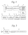
- the basic signal processing chain for a color flow imaging system comprises an ultrasound transducer array 2, which is activated to transmit pulse sequences comprising tone bursts of ultrasound waves of length P which are fired repeatedly at the PRF.
- the return reflected RF ultrasound waves are detected by the transducer elements and received by the respective receive channels in the beamformer 4.
- the beamformer sums the delayed channel data and outputs a beamsummed signal, which is demodulated into in-phase and quadrature (I/Q) signal components by a demodulator 6.
- the I/Q signal components are stored in a comer turner memory 8, whose purpose is to buffer data from possibly interleaved firings and output the data as vectors of points across firings at a given range cell.
- Data is received in "fast time”, or sequentially down range (along a vector) for each firing.
- the output of the comer turner memory is reordered into “slow time”, or sequentially by firing for each range cell.
- the resultant "slow time” I/Q signal samples are passed through respective wall filters 10, which reject any clutter corresponding to stationary or very slow-moving tissue.
- the filtered outputs are then fed into a parameter estimator 12, which converts the range cell information into the intermediate autocorrelation parameters N, D and R(O) .
- N and D are the numerator and denominator for the autocorrelation equation, as shown below: where I i and Q i are the demodulated, basebanded input data for firing i, and M is the number of firings in the packet. R(O) is approximated as a finite sum over the number of firings in a packet, as follows:
- a processor converts N and D into a magnitude and phase for each range cell.
- the equations used are as follows:
- N 2 + D 2
- the parameter estimator processes the magnitude and phase values into estimates of power, velocity and turbulence.
- the phase is used to calculate the mean Doppler frequency, which is proportional to the velocity as shown below; R(O) and
- the mean Doppler frequency in hertz is obtained from the phase of N and D and the pulse repetition time T :
- the parameter estimator does not calculate the mean Doppler frequency as an intermediate output, but calculates v directly from the phase output of the processor using a look-up table.
- the turbulence may be calculated in the time domain as a second-order series expansion of the variance of the mean Doppler frequency.
- the time domain expression for turbulence involves calculating the zero-lag and one-lag autocorrelation functions, R(O) and R(T) respectively.
- the exact autocorrelation functions are approximated by finite sums over the known data in the number of firings in a packet:
- the mean value signal ⁇ (R(T)) is an estimate of the mean Doppler frequency shift of the flowing reflectors, which in turn is proportional to the mean blood flow velocity.
- the variance signal ⁇ 2 indicates the frequency spread of the flow signal component of the baseband echo signal. This value is indicative of flow turbulence, since laminar flow has a very narrow range of velocities, while turbulent flow is a mixture of many velocities.
- the signal R(O) indicates the amount of the returned power in the Doppler-shifted flow signal.
- the color flow estimates are sent to a scan converter 14, which converts the color flow image data into X-Y format frames for video display and stores the frames in memory 15.
- the scan-converted frames are passed to a video processor 16, which basically maps the video data to a display color map for video display.
- the color flow image frames are then sent to the video monitor 18 for display.
- either velocity or power are displayed alone or velocity is displayed in conjunction with either power or turbulence.
- System control is centered in a host computer (not shown), which accepts operator inputs through an operator interface (e.g., a keyboard) and in turn controls the various subsystems.
- the present invention may be incorporated in a system of the type depicted in FIG. 1 or other compatible color flow imaging systems.
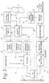
- the preferred embodiment is shown in FIG. 2.
- System control is centered in a master controller or processor 20 (or host computers), which accepts operator inputs through an operator interface 22 and in turn controls the various subsystems.
- the master controller 20 also generates the system timing and control signals which are distributed via various control buses.
- the transducer array 2 consists of a plurality of separately driven transducer elements 2', each of which produces a burst of ultrasonic energy (i.e., ultrasound waves) when energized by a pulsed waveform produced by a transmitter 24.
- the ultrasonic energy (i.e., ultrasound waves) reflected back to transducer array 2 from the object under study is converted to an electrical signal by each receiving transducer element 2' and applied separately to a receiver 26 through a set of transmit/receive (T/R) switches 28.
- Transmitter 24 and receiver 26 are operated under control of master controller 20.
- a complete scan is performed by acquiring a series of echoes in which transmitter 24 is gated ON momentarily to energize each transducer element 2', and the subsequent echo signals produced by each transducer element 2' are applied to receiver 26.
- a channel may begin reception while another channel is still transmitting.
- the receiver 26 combines the separate echo signals from each transducer element to produce a single echo signal which is used to produce a line in an image on the display monitor.
- each transducer element 2' in the transmit aperture is pulsed by a pulse waveform output by a respective pulser 32 in response to a respective transmit sequence output to that pulser from the transmit sequence memory 30.
- the length of each pulse waveform is proportional to the number of bits in the respective digital transmit sequence.
- FIG. 3 shows one such transmit sequence stored in transmit sequence memory 30 for driving a transducer element 2' with a burst of four cycles.
- the +1 and -1 elements of each transmit sequence are transformed into pulses of opposite phase.
- the transmitter 14 drives transducer array 2 such that the ultrasonic energy is transmitted as a directed focused beam.
- respective time delays are imparted to the pulsers 32 by a transmit focus delay block 34, while respective peak pulse amplitudes are set by transmit level control block 36.
- the master controller 20 determines the conditions under which the acoustic pulses will be transmitted. With this information, the transmit focus delay and transmit level control blocks will respectively determine the timing and the amplitude of each of the transmit pulses to be generated by the pulsers 32.
- the pulsers 32 in turn send the transmit pulses to respective elements 2' of the transducer array 2 via the T/R switches 28, which protect the time-gain control (TGC) amplifiers 38 from the high voltages which may exist at the transducer array.
- TGC time-gain control
- Receiver 26 amplifies the separate echo signals via a respective TGC amplifier 38 in each receive channel.
- the amplified echo signals are then fed to the receive beamformer 40, which imparts the proper time delays to the respective amplified echo signals.
- the receive time delays like the transmit time delays, are provided under the control of the master controller.
- the receive time delays may be read out from look-up tables stored in random access memory.
- the receive beamformer 40 sums the time-delayed signals to provide an echo signal which accurately indicates the total ultrasonic energy reflected from a point located at a particular range along the ultrasonic beam.
- the beamsummed receive signals are output to the demodulator 6, which forms the I and Q baseband components. These baseband components are bandpass-filtered in respective receive filters 42, which preferably take the form of finite impulse response filters.
- the filter coefficients are provided to the receive filters 42 from a filter coefficient memory 44 under the control of master controller 20. The bandwidth of the receive filters can be adjusted by changing the filter coefficients.
- the filtered outputs are then processed by the color flow processor, i.e., comer turner memory 8, wall filters 10 and a parameter estimator 12 shown in FIG. 1.
- the parameter estimator preferably includes a velocity estimator which estimates velocity as a function of the phase shift in the backscattered signals.
- a subject being studied S is fitted with a conventional detector of heart activity 17 which transmits signals over a conductor 23 to a systole detector 21, such as a conventional ECG machine.
- Detector 21 detects systole of the heart of the subject and transmits a signal to master controller 20 that initiates a mode of operation illustrated in FIG. 4.
- the systole signal is received at time T1, and in response to the signal, the master controller causes transmit level control 36 to energize pulsars 32 so that transducer array 2 generates ultrasound waves with high acoustic output that result in several frames of high acoustic output (HAO) between times T1 and T2.
- the HAO is indicated by power level P2 in FIG. 4.
- the HAO approaches the MI (mechanical index) FDA limit with a sufficient dwell time between the HAO frames to limit the temporal average to below the FDA limit.
- One such dwell time is from time T2 to time T3, during which master controller 20 causes transmit level control 36 to energize pulsars 32 so that transducer array 2 transmits ultrasound waves into subject S at a lower acoustic power (LAO) illustrated by power level P1 in FIG. 4.
- the power level P0 in FIG. 4 indicates no scanning of the subject, i.e., no transmission of ultrasound waves by transducer array 2.
- HAO frames interspersed with LAO frames More specifically, HAO frames HAO1 and HAO2 are separated by LAO frames LAO1. Likewise, HAO frames HAO2 and HAO3 are separated by LAO frames LAO2.
- a series of LAO frames designated LAO3 in FIG. 4 follow HAO frames HAO3.
- the HAO1 frames are generated between times T1 and T2; the LAO1 frames are generated between times T2 and T3; the HAO2 frames are generated between times T3 and T4; the LAO2 frames are generated between times T4 and T5; the HAO3 frames are generated between times T5 and T6 and the LAO3 frames are generated between times T6 and T7.
- the HAO frames are generated during a substantially smaller time period then the LAO frames.
- the HAO frames are inserted sparsely between many LAO frames to limit the ISPTA over a time interval greater than a single frame but less than the thermal time constant of tissue.
- the preferred approach is to trigger one or more of the HAO frames at systole, when flow from the heart of a subject S is greatest in the region of interest, with several LAO frames in between. For example, referring to FIG. 4, systole occurs at times T1, T3 and T5, thereby initiating generating of HAO frames, HAO1, HAO2 and HAO3, respectively.
- the HAO frames are used to discriminate between image regions with flow and those without flow. Where no flow is present in an HAO frame, no flow is allowed in display 18.
- the regions of the HAO frames with flow are updated by flow estimates in the LAO frames to maintain good tempcral resolution, i.e., frame rate, all providing better penetration and flow segmentation.
- an exemplary time period for generating frames HAO1 is approximately 200 milliseconds.
- An exemplary time period for generating frames LAOI is approximately 800 milliseconds.
- the time periods for generating each of the HAO frames may be identical; the time periods for generating each of the LAO frames also may be identical.
- FIGS. 5 and 6 illustrate two different techniques for generating still (frozen) images. According to these techniques, a user pushes a "flash-freeze" key 19 on operator inputs 22 (Fig. 2). The system responds in three steps:
- a still frozen image may be obtained by having the user press key 19 (FIG. 2) to which the system also responds in three steps:
- the system pauses a minimum time to insure that the ISPTA is not exceeded. This approach provides a frozen image with increased penetration on display 18.
Landscapes
- Engineering & Computer Science (AREA)
- Physics & Mathematics (AREA)
- Remote Sensing (AREA)
- Radar, Positioning & Navigation (AREA)
- Computer Networks & Wireless Communication (AREA)
- General Physics & Mathematics (AREA)
- Health & Medical Sciences (AREA)
- Life Sciences & Earth Sciences (AREA)
- Acoustics & Sound (AREA)
- Nuclear Medicine, Radiotherapy & Molecular Imaging (AREA)
- Public Health (AREA)
- Medical Informatics (AREA)
- Molecular Biology (AREA)
- Surgery (AREA)
- Animal Behavior & Ethology (AREA)
- General Health & Medical Sciences (AREA)
- Heart & Thoracic Surgery (AREA)
- Veterinary Medicine (AREA)
- Biomedical Technology (AREA)
- Radiology & Medical Imaging (AREA)
- Pathology (AREA)
- Biophysics (AREA)
- Ultra Sonic Daignosis Equipment (AREA)
- Surgical Instruments (AREA)
Abstract
Description


Claims (10)
- An ultrasound imaging system for penetrating a subject (S) being studied with ultrasound waves and displaying a color flow image representing at least a portion of the subject, comprising:a transducer array (2) operable in response to a first command for transmitting ultrasound waves with a first power toward a portion of the subject and receiving first reflected ultrasound waves from the portion and operable in response to a second command for transmitting ultrasound waves with a second power less than the first power toward the portion of the subject and receiving second reflected ultrasound waves from the portion;an ultrasound receiver (26) connected to generate a first set of signals in response to the first reflected ultrasound waves and connected to generate a second set of signals in response to the second reflected ultrasound waves;a processor (20) generating the first command for a first time period and generating the second command for a second time period, the ratio of the first time period to the second time period enabling compliance with said mechanical index, temperature and intensity spatial peak temporal average specifications while enabling penetration of said ultrasound waves during the first time period, and processing the first set of signals and the second set of signals to generate processed color flow data for display as a color flow image; anda display (18) displaying a color flow image in response to said processed color flow data.
- Apparatus, as claimed in claim 1, wherein the first time period is sufficient to generate a frame of said first scan data.
- Apparatus, as claimed in claim 1, wherein the first power approaches the mechanical index specification and wherein said first command comprises a series of first commands with sufficient dwell time between the first commands to comply with said mechanical index, temperature and intensity spatial peak temporal average specifications.
- Apparatus, as claimed in claim 1, wherein said processor identifies flow data within the first scan data representing a region of fluid flow within the portion of the subject.
- Apparatus, as claimed in claim 1, wherein said first time period is a predetermined time period, wherein said second time period is a predetermined time period, and wherein said processor enables the display of still color images by generating said second command for said predetermined second time period and generating said first command for said predetermined first time period.
- An ultrasound imaging method for penetrating a subject (S) being studied with ultrasound waves and displaying a color flow image representing at least a portion of the subject, comprising:transmitting first ultrasound waves with a first power toward a portion of the subject in response to a first command;receiving first reflected ultrasound waves from the portion in response to the first ultrasound waves;transmitting second ultrasound waves with a second power less than the first power toward the portion of the subject in response to a second command;receiving second reflected ultrasound waves from the portion in response to the second ultrasound waves;generating a first set of signals in response to the first reflected ultrasound waves;generating a second set of signals in response to the second reflected ultrasound waves; generating the first command for a first time period;generating the second command for a second time period, the ratio of the first time period to the second time period enabling compliance with said mechanicalindex, temperature and intensity spatial peak temporal average specifications while enabling penetration of said ultrasound waves during the first time period;processing the first set of signals and the second set of signals to generate processed color flow data for display as a color flow image; anddisplaying a color flow image in response to said processed color flow data.
- A method, as claimed in claim 6, wherein the first time period is sufficient to generate a frame of said first set of signals.
- A method, as claimed in claim 6, wherein the first power approaches the mechanical index specification and wherein said first command comprises a series of first commands with sufficient dwell time between the first commands to comply with said mechanical index, temperature and intensity spatial peak temporal average specifications.
- A method, as claimed in claim 6, and further comprising identifying flow data within the first set of signals representing a region of fluid flow within the portion of the subject.
- A method, as claimed in claim 6, wherein said first time period is a predetermined time period, wherein said second time period is a predetermined time period, and wherein said displaying comprises displaying a still color image by generating said second command for said predetermined second time period and generating said first command for said predetermined first time period.
Applications Claiming Priority (2)
| Application Number | Priority Date | Filing Date | Title |
|---|---|---|---|
| US09/456,859 US6210335B1 (en) | 1999-12-08 | 1999-12-08 | Acoustic flash to increase penetration |
| US456859 | 1999-12-08 |
Publications (3)
| Publication Number | Publication Date |
|---|---|
| EP1107020A2 true EP1107020A2 (en) | 2001-06-13 |
| EP1107020A3 EP1107020A3 (en) | 2004-06-09 |
| EP1107020B1 EP1107020B1 (en) | 2006-03-08 |
Family
ID=23814419
Family Applications (1)
| Application Number | Title | Priority Date | Filing Date |
|---|---|---|---|
| EP00310914A Expired - Lifetime EP1107020B1 (en) | 1999-12-08 | 2000-12-08 | Acoustic flash to increase penetration |
Country Status (4)
| Country | Link |
|---|---|
| US (1) | US6210335B1 (en) |
| EP (1) | EP1107020B1 (en) |
| JP (1) | JP4659973B2 (en) |
| DE (1) | DE60026471T2 (en) |
Cited By (1)
| Publication number | Priority date | Publication date | Assignee | Title |
|---|---|---|---|---|
| WO2006051818A1 (en) | 2004-11-10 | 2006-05-18 | Hisamitsu Pharmaceutical Co., Inc. | Drug for external use and adhesive patch |
Families Citing this family (36)
| Publication number | Priority date | Publication date | Assignee | Title |
|---|---|---|---|---|
| US6315728B1 (en) * | 1999-12-21 | 2001-11-13 | General Electric Company | Ultrasound color flow adaptive scanning techniques |
| US6413218B1 (en) * | 2000-02-10 | 2002-07-02 | Acuson Corporation | Medical diagnostic ultrasound imaging system and method for determining an acoustic output parameter of a transmitted ultrasonic beam |
| US6436045B1 (en) * | 2000-04-27 | 2002-08-20 | Koninklijke Phillips Electronics N.V. | User controlled destructive waveform routine for ultrasound systems |
| GB0205674D0 (en) * | 2002-03-11 | 2002-04-24 | Qinetiq Ltd | High resolution radiation imaging |
| US6824518B2 (en) | 2002-11-26 | 2004-11-30 | Siemens Medical Solutions Usa, Inc. | High transmit power diagnostic ultrasound imaging |
| JP4801912B2 (en) * | 2004-03-24 | 2011-10-26 | 株式会社東芝 | Ultrasonic diagnostic equipment |
| US8234923B2 (en) * | 2004-09-20 | 2012-08-07 | Innervision Medical Technologies Inc. | Systems and methods for ultrasound imaging |
| WO2007092054A2 (en) | 2006-02-06 | 2007-08-16 | Specht Donald F | Method and apparatus to visualize the coronary arteries using ultrasound |
| EP2088932B1 (en) | 2006-10-25 | 2020-04-08 | Maui Imaging, Inc. | Method and apparatus to produce ultrasonic images using multiple apertures |
| US9247926B2 (en) | 2010-04-14 | 2016-02-02 | Maui Imaging, Inc. | Concave ultrasound transducers and 3D arrays |
| US9282945B2 (en) | 2009-04-14 | 2016-03-15 | Maui Imaging, Inc. | Calibration of ultrasound probes |
| US9339256B2 (en) | 2007-10-01 | 2016-05-17 | Maui Imaging, Inc. | Determining material stiffness using multiple aperture ultrasound |
| US9788813B2 (en) | 2010-10-13 | 2017-10-17 | Maui Imaging, Inc. | Multiple aperture probe internal apparatus and cable assemblies |
| US20100016719A1 (en) * | 2008-07-16 | 2010-01-21 | Siemens Medical Solutions Usa, Inc. | Adaptive regulation of acoustic output power in medical ultrasound imaging |
| JP5485373B2 (en) | 2009-04-14 | 2014-05-07 | マウイ イマギング,インコーポレーテッド | Multiple aperture ultrasonic array alignment system |
| KR102322776B1 (en) | 2010-02-18 | 2021-11-04 | 마우이 이미징, 인코포레이티드 | Method of constructing an ultrasound image and multi-aperture ultrasound imaging system therefor |
| JP5414581B2 (en) * | 2010-03-12 | 2014-02-12 | 株式会社東芝 | Ultrasonic diagnostic equipment |
| CN102451018B (en) * | 2010-10-25 | 2015-09-30 | 深圳迈瑞生物医疗电子股份有限公司 | Diasonograph beam transmission method and diasonograph |
| JP5254389B2 (en) * | 2011-03-18 | 2013-08-07 | 富士フイルム株式会社 | Ultrasonic diagnostic apparatus and ultrasonic image generation method |
| JP6407719B2 (en) | 2011-12-01 | 2018-10-17 | マウイ イマギング,インコーポレーテッド | Motion detection using ping base and multi-aperture Doppler ultrasound |
| JP2015503404A (en) | 2011-12-29 | 2015-02-02 | マウイ イマギング,インコーポレーテッド | Arbitrary path M-mode ultrasound imaging |
| EP2833791B1 (en) | 2012-03-26 | 2022-12-21 | Maui Imaging, Inc. | Methods for improving ultrasound image quality by applying weighting factors |
| CN104620128B (en) | 2012-08-10 | 2017-06-23 | 毛伊图像公司 | Calibration of Multi-aperture Ultrasonic Probes |
| US9986969B2 (en) | 2012-09-06 | 2018-06-05 | Maui Imaging, Inc. | Ultrasound imaging system memory architecture |
| CN103676827A (en) | 2012-09-06 | 2014-03-26 | Ip音乐集团有限公司 | System and method for remotely controlling audio equipment |
| WO2014160291A1 (en) | 2013-03-13 | 2014-10-02 | Maui Imaging, Inc. | Alignment of ultrasound transducer arrays and multiple aperture probe assembly |
| US9883848B2 (en) | 2013-09-13 | 2018-02-06 | Maui Imaging, Inc. | Ultrasound imaging using apparent point-source transmit transducer |
| US10401493B2 (en) | 2014-08-18 | 2019-09-03 | Maui Imaging, Inc. | Network-based ultrasound imaging system |
| CN107613878B (en) | 2015-03-30 | 2021-04-06 | 毛伊图像公司 | Ultrasound imaging system and method for detecting object motion |
| EP4697068A3 (en) | 2016-01-27 | 2026-04-22 | Maui Imaging, Inc. | Ultrasound imaging with sparse array probes |
| CN108761414B (en) * | 2018-05-25 | 2022-05-20 | 电子科技大学 | S-shaped interference wave beam testing method based on frequency control array |
| US12290409B2 (en) * | 2018-12-31 | 2025-05-06 | General Electric Company | Method and systems for increasing transmit power during an ultrasound scan |
| CN110477955B (en) * | 2019-08-22 | 2021-05-11 | 电子科技大学 | An automatic identification method of blood vessels based on IQ data |
| JP7724853B2 (en) | 2020-10-21 | 2025-08-18 | マウイ イマギング,インコーポレーテッド | Systems and methods for tissue characterization using multiple aperture ultrasound |
| EP4236811A4 (en) | 2020-11-02 | 2024-10-09 | Maui Imaging, Inc. | SYSTEMS AND METHODS FOR ENHANCING ULTRASOUND IMAGE QUALITY |
| CN117979908A (en) * | 2021-09-21 | 2024-05-03 | 富士胶片株式会社 | Ultrasonic diagnostic system and working method of ultrasonic diagnostic system |
Family Cites Families (9)
| Publication number | Priority date | Publication date | Assignee | Title |
|---|---|---|---|---|
| US5509413A (en) * | 1993-08-11 | 1996-04-23 | Kabushiki Kaisha Toshiba | Ultrasonic diagnostic apparatus |
| US5443071A (en) * | 1994-10-11 | 1995-08-22 | Siemens Medical Systems, Inc. | Quantitative color flow |
| US5694937A (en) * | 1995-01-31 | 1997-12-09 | Kabushiki Kaisha Toshiba | Ultrasound diagnostic apparatus and method |
| US5735281A (en) * | 1996-08-09 | 1998-04-07 | Hewlett-Packard Company | Method of enhancing and prolonging the effect of ultrasound contrast agents |
| GB9701274D0 (en) * | 1997-01-22 | 1997-03-12 | Andaris Ltd | Ultrasound contrast imaging |
| US6110120A (en) * | 1997-04-11 | 2000-08-29 | Acuson Corporation | Gated ultrasound imaging apparatus and method |
| US5860928A (en) * | 1997-08-07 | 1999-01-19 | Siemens Medical Systems, Inc. | Method and system for selectively smoothing color flow images in an ultrasound system |
| JPH11276482A (en) * | 1998-03-26 | 1999-10-12 | Fujitsu Ltd | Ultrasound diagnostic equipment |
| US6048312A (en) * | 1998-04-23 | 2000-04-11 | Ishrak; Syed Omar | Method and apparatus for three-dimensional ultrasound imaging of biopsy needle |
-
1999
- 1999-12-08 US US09/456,859 patent/US6210335B1/en not_active Expired - Lifetime
-
2000
- 2000-12-07 JP JP2000372233A patent/JP4659973B2/en not_active Expired - Lifetime
- 2000-12-08 EP EP00310914A patent/EP1107020B1/en not_active Expired - Lifetime
- 2000-12-08 DE DE60026471T patent/DE60026471T2/en not_active Expired - Lifetime
Cited By (1)
| Publication number | Priority date | Publication date | Assignee | Title |
|---|---|---|---|---|
| WO2006051818A1 (en) | 2004-11-10 | 2006-05-18 | Hisamitsu Pharmaceutical Co., Inc. | Drug for external use and adhesive patch |
Also Published As
| Publication number | Publication date |
|---|---|
| EP1107020A3 (en) | 2004-06-09 |
| DE60026471D1 (en) | 2006-05-04 |
| EP1107020B1 (en) | 2006-03-08 |
| US6210335B1 (en) | 2001-04-03 |
| JP2001198124A (en) | 2001-07-24 |
| JP4659973B2 (en) | 2011-03-30 |
| DE60026471T2 (en) | 2006-10-12 |
Similar Documents
| Publication | Publication Date | Title |
|---|---|---|
| EP1107020B1 (en) | Acoustic flash to increase penetration | |
| EP0948931B1 (en) | Ultrasound imaging using coded excitation on transmit and selective filtering on receive | |
| EP0947853B1 (en) | Method and apparatus for enhanced flow imaging in b-mode ultrasound | |
| EP0952462A2 (en) | Method and apparatus for improving visualization of biopsy needle in ultrasound imaging | |
| US5938611A (en) | Method and apparatus for color flow imaging using coded excitation with single codes | |
| EP1046928B1 (en) | Method and apparatus for flow imaging using coded excitation | |
| US5456257A (en) | Ultrasonic detection of contrast agents | |
| EP0008517B1 (en) | Duplex ultrasonic imaging system with repetitive excitation of common transducer in doppler modality | |
| US5445156A (en) | Method for adaptively filtering doppler signals using a complex time domain filter | |
| US6267725B1 (en) | Individual channel analog wall filtering to improve flow sensitivity in ultrasound imaging | |
| US6312384B1 (en) | Method and apparatus for flow imaging using golay codes | |
| US6108572A (en) | Method and apparatus for harmonic imaging using multiple focal zones | |
| CN107049361B (en) | Sound velocity imaging using shear waves | |
| US6045507A (en) | Method and apparatus for adaptive color flow optimization | |
| US6599248B1 (en) | Method and apparatus for ultrasound diagnostic imaging | |
| US5501224A (en) | Ultrasonic diagnostic apparatus | |
| US5871447A (en) | Doppler energy-related parameters in an ultrasound imaging system | |
| JP2004195228A (en) | Adaptive filtering in ultrasonic imaging using optimized transmission sequence | |
| JPH11309146A (en) | System and method for imaging a stream of ultrasonic scatterers | |
| CN100594392C (en) | Multi-region color Doppler beam transmitting method | |
| EP1006369A2 (en) | Method and apparatus for adaptive filtering by counting acoustic sample zeroes in ultrasound imaging | |
| JP4746758B2 (en) | Ultrasound image display by combining enhanced flow imaging in B mode and color flow mode | |
| JP2815622B2 (en) | Ultrasound diagnostic equipment | |
| JPH03272751A (en) | Ultrasonic diagnostic device | |
| JPH0327209B2 (en) |
Legal Events
| Date | Code | Title | Description |
|---|---|---|---|
| PUAI | Public reference made under article 153(3) epc to a published international application that has entered the european phase |
Free format text: ORIGINAL CODE: 0009012 |
|
| AK | Designated contracting states |
Kind code of ref document: A2 Designated state(s): AT BE CH CY DE DK ES FI FR GB GR IE IT LI LU MC NL PT SE TR |
|
| AX | Request for extension of the european patent |
Free format text: AL;LT;LV;MK;RO;SI |
|
| PUAL | Search report despatched |
Free format text: ORIGINAL CODE: 0009013 |
|
| AK | Designated contracting states |
Kind code of ref document: A3 Designated state(s): AT BE CH CY DE DK ES FI FR GB GR IE IT LI LU MC NL PT SE TR |
|
| AX | Request for extension of the european patent |
Extension state: AL LT LV MK RO SI |
|
| 17P | Request for examination filed |
Effective date: 20041209 |
|
| AKX | Designation fees paid |
Designated state(s): DE NL |
|
| 17Q | First examination report despatched |
Effective date: 20050119 |
|
| GRAP | Despatch of communication of intention to grant a patent |
Free format text: ORIGINAL CODE: EPIDOSNIGR1 |
|
| GRAS | Grant fee paid |
Free format text: ORIGINAL CODE: EPIDOSNIGR3 |
|
| GRAA | (expected) grant |
Free format text: ORIGINAL CODE: 0009210 |
|
| AK | Designated contracting states |
Kind code of ref document: B1 Designated state(s): DE NL |
|
| REF | Corresponds to: |
Ref document number: 60026471 Country of ref document: DE Date of ref document: 20060504 Kind code of ref document: P |
|
| PLBE | No opposition filed within time limit |
Free format text: ORIGINAL CODE: 0009261 |
|
| STAA | Information on the status of an ep patent application or granted ep patent |
Free format text: STATUS: NO OPPOSITION FILED WITHIN TIME LIMIT |
|
| 26N | No opposition filed |
Effective date: 20061211 |
|
| PGFP | Annual fee paid to national office [announced via postgrant information from national office to epo] |
Ref country code: DE Payment date: 20131230 Year of fee payment: 14 |
|
| PGFP | Annual fee paid to national office [announced via postgrant information from national office to epo] |
Ref country code: NL Payment date: 20131226 Year of fee payment: 14 |
|
| REG | Reference to a national code |
Ref country code: DE Ref legal event code: R119 Ref document number: 60026471 Country of ref document: DE |
|
| REG | Reference to a national code |
Ref country code: NL Ref legal event code: V1 Effective date: 20150701 |
|
| REG | Reference to a national code |
Ref country code: NL Ref legal event code: V1 Effective date: 20150701 |
|
| PG25 | Lapsed in a contracting state [announced via postgrant information from national office to epo] |
Ref country code: NL Free format text: LAPSE BECAUSE OF NON-PAYMENT OF DUE FEES Effective date: 20150701 |
|
| PG25 | Lapsed in a contracting state [announced via postgrant information from national office to epo] |
Ref country code: DE Free format text: LAPSE BECAUSE OF NON-PAYMENT OF DUE FEES Effective date: 20150701 |