EP1106826A2 - Flow rate control with a positive displacement liquid pump - Google Patents
Flow rate control with a positive displacement liquid pump Download PDFInfo
- Publication number
- EP1106826A2 EP1106826A2 EP00126636A EP00126636A EP1106826A2 EP 1106826 A2 EP1106826 A2 EP 1106826A2 EP 00126636 A EP00126636 A EP 00126636A EP 00126636 A EP00126636 A EP 00126636A EP 1106826 A2 EP1106826 A2 EP 1106826A2
- Authority
- EP
- European Patent Office
- Prior art keywords
- liquid
- positive displacement
- pressure
- diaphragm
- delivery
- Prior art date
- Legal status (The legal status is an assumption and is not a legal conclusion. Google has not performed a legal analysis and makes no representation as to the accuracy of the status listed.)
- Granted
Links
Images


Classifications
-
- F—MECHANICAL ENGINEERING; LIGHTING; HEATING; WEAPONS; BLASTING
- F04—POSITIVE - DISPLACEMENT MACHINES FOR LIQUIDS; PUMPS FOR LIQUIDS OR ELASTIC FLUIDS
- F04B—POSITIVE-DISPLACEMENT MACHINES FOR LIQUIDS; PUMPS
- F04B13/00—Pumps specially modified to deliver fixed or variable measured quantities
-
- F—MECHANICAL ENGINEERING; LIGHTING; HEATING; WEAPONS; BLASTING
- F04—POSITIVE - DISPLACEMENT MACHINES FOR LIQUIDS; PUMPS FOR LIQUIDS OR ELASTIC FLUIDS
- F04B—POSITIVE-DISPLACEMENT MACHINES FOR LIQUIDS; PUMPS
- F04B43/00—Machines, pumps, or pumping installations having flexible working members
- F04B43/02—Machines, pumps, or pumping installations having flexible working members having plate-like flexible members, e.g. diaphragms
-
- F—MECHANICAL ENGINEERING; LIGHTING; HEATING; WEAPONS; BLASTING
- F04—POSITIVE - DISPLACEMENT MACHINES FOR LIQUIDS; PUMPS FOR LIQUIDS OR ELASTIC FLUIDS
- F04B—POSITIVE-DISPLACEMENT MACHINES FOR LIQUIDS; PUMPS
- F04B2205/00—Fluid parameters
- F04B2205/07—Pressure difference over the pump
Definitions
- the present invention relates to a positive displacement type liquid-delivery apparatus that can be used to deliver a very small amount of liquid at a constant rate to various processing apparatuses such as a chemical vapor deposition apparatus.
- a metallic oxide film material such as tantalum pentaoxide (Ta 2 O 5 ) having dielectric constant of approximately 20, or barium titanate (BaTiO 3 ) or strontium titanate (SrTiO 3 ) or barium strontium titanate having dielectric constant of approximately 300 is considered to be a promising thin-film material.
- a gaseous mixture made by mixing one or more gas feed materials of organometallic compounds and an oxygen containing gas is ejected to a substrate heated to a certain temperature.
- Organometallic gaseous feed material is chosen by the nature of the thin film to be produced.
- a metallic oxide film comprised by barium strontium titanate is produced by first converting Ba, Sr, Ti or their compounds into their dipivaloylmethane (DPM) compounds, and dissolving these compounds in an organic solvent such as tetrahydrofuran (THF) to produce respective liquid feed materials. After uniformly mixing these liquid feed materials in a required proportion to produce a master liquid feed, such master liquid feed is sent to a vaporizer to produce a gaseous feed for use in the chemical vapor deposition apparatus.
- DPM dipivaloylmethane
- THF tetrahydrofuran
- Such master liquid feed is extremely susceptible to degradation even in a sealed container, and therefore it is undesirable to have such a master liquid feed stagnate inside delivery piping.
- the master liquid feed is especially susceptible to producing precipitate particles, by being heated or being exposed to air, which tend to produce inferior quality films. Therefore, once the component liquids are mixed into a master liquid feed, it is necessary that the master liquid feed be maintained in a stable condition. It is also desirable that the master liquid feed be completely used up as quickly as practicable.
- the film deposition apparatus be capable of exercising a fine control of the flow rate of the master liquid feed over a wide range of flow rates from a very small flow rate to a large flow rate. Therefore, the liquid-delivering apparatus should be capable of providing a stringent control of the flow rates of the liquid feed.
- a mass flow controller MFC
- a processing apparatus such as a vaporizer
- the feed liquid tank is pressurized with gas or the like to deliver liquid and a control valve on the MFC is adjusted to control a delivery rate of liquid.
- Positive displacement pumps incorporating pistons, diaphragms, and the like are also used.
- a positive displacement pump can overcome these drawbacks, a piston pump cannot be used because the sliding parts of the pump generate particles that contaminate the liquid.
- the positive displacement pumps employing bellows or diaphragms do not contaminate the liquid, but present the following problems.
- a positive displacement pump in which a container is partitioned by a diaphragm into two chambers, i.e., a liquid delivery chamber and a working fluid chamber, and an incompressible liquid is used as a working fluid.
- the diaphragm moves according to the amount of the working fluid supplied to the working fluid chamber for thereby discharging liquid from the container. Therefore, the precision in controlling the flow rate is more or less dependent on the precision of the external driving system.
- an external device is required for pumping the working fluid, and hence troublesome handling of the working fluid is necessary and the overall apparatus becomes large-sized.
- a driving device for driving the diaphragm is constructed mechanically, then these problems are eliminated and the overall apparatus becomes simple.
- Installing a flow meter in the secondary side of the container for performing feedback control it is not possible to obtain a better performance than that of the mass flow controller, because a precision and reproducibility of the flow meter is the same level as the mass flow controller.
- the pressure in the secondary side of the positive displacement pump slowly decreases due to a small leak in the check valve provided in the primary side (upstream side) of the processing apparatus (the part to which liquid is supplied). This may lead to a pressure drop when the liquid-delivery resumes, requiring time to stabilize the flow rate of liquid and potentially causing other problems.
- the pressure in the processing apparatus is below atmospheric pressure, the liquid feed may be vaporized because the pressure in the primary side of the check valve drops below the vapor pressure of the liquid feed.
- a positive displacement type liquid-delivery apparatus employing a positive displacement pump with a flexible diaphragm which can supply liquid at a constant rate with high precision and high reproducibility, shorten the time required to stabilize the liquid-delivery from starting of pumping operation, and control the flow rate of liquid immediately after the pumping operation begins.
- a positive displacement liquid-delivery apparatus comprising: a positive displacement pump comprising a housing having a liquid-delivery chamber divided by a flexible diaphragm and a diaphragm driving unit linked to the diaphragm to discharge fluid from the liquid-delivery chamber; and a differential pressure control unit for controlling the differential pressure between both sides of the diaphragm at a constant value during the pumping process.
- the construction of the apparatus is simplified because the diaphragm is driven directly by the diaphragm driving unit. Further, by keeping the differential pressure between both sides of the diaphragm at a constant value, it is possible to keep the diaphragm at a constant amount of deformation, thus eliminating error caused by the diaphragm deformation. Hence, the diaphragm driving unit can control the amount of deformation in the diaphragm to perform precise flow rate control.
- the differential pressure control unit comprises a differential pressure sensor for detecting the differential pressure between both sides of the diaphragm, and a control valve for controlling the flow rate of the liquid discharged from the liquid-delivery chamber on a basis of a signal from the differential pressure sensor.
- the differential pressure of the diaphragm is controlled so as to be constant, thus causing the flow rate of liquid to be controlled indirectly.
- the pressure sensor is required to be used only the space on the side facing the liquid-delivery chamber.
- a predetermined amount of liquid is not exactly delivered at the secondary side of the diaphragm in accordance with the moving distance of the diaphragm.
- the differential pressure of the both sides of the diaphragm varies, the amount of deformation of the diaphragm varies in accordance with the differential pressure, and hence the delivery amount of liquid is deviated from the predetermined amount of liquid. Therefore, it is necessary to control the differential pressure of the diaphragm at a constant value.
- the amount of delivery liquid corresponds to the amount of deformation of the diaphragm at the differential pressure. Since the amount of delivery liquid is estimated from the relationship between the position of the diaphragm and the differential pressure, a predetermined amount of delivery liquid can be exactly obtained.
- a flow sensor is disposed on a discharge path and control is performed based on a signal from the flow sensor when the pressure in the liquid-delivery chamber during the pumping process exceeds a prescribed value or the absolute value of the rate of pressure variations exceeds a prescribed value.
- the liquid-delivery chamber is arranged so as to achieve the required discharge flow volume of the fluid in one stroke.
- the bellows operation is always stable and uniform for each process, thereby avoiding pressure and flow rate variations, for example, that occur when switching valves in alternate operations. Performing one pump operation using only a portion of one stroke can further increase the life of the bellows.
- the required discharge flow volume of the fluid is such volume that a predetermined film is formed on one substrate (semiconductor wafer) in one stroke, or more than such volume.
- the gas is employed to pressurize the space on the opposite side of the diaphragm from the liquid-delivery chamber.
- the diaphragm itself has an allowable differential pressure between the both sides of the bellows.
- this differential pressure is small or the pressure required in the processing apparatus on the secondary side of the pump is larger than the allowable differential pressure, liquid-delivery cannot be performed if the pressure on the side of the diaphragm opposite from the liquid-delivery is atmospheric pressure.
- the gas pressure P Since the differential pressure of the diaphragm must be maintained at a constant value as described above in order to supply the fluid at a constant flow rate, the gas pressure P must also be constant.
- the volume V on the side of the diaphragm opposite the liquid-delivery chamber varies during pumping operations. Accordingly, the side of the diaphragm opposite the liquid-delivery chamber should be supplied with an amount of gas based on the liquid-delivery amount ⁇ V, that is, ⁇ V ⁇ P.
- the method of controlling the differential pressure both sides of the diaphragm can be applied for using the pressure of the gas and the liquid, and controlling the pressure on the gas side.
- the injection and discharge of gas requires some time, resulting in control delays when pressure variations occur abruptly.
- variations in the differential pressure may occur more frequently, making it difficult to maintain a prescribed amount of liquid.
- this method may be suitable for processes that have no severe pressure variations.
- a leak sensor can be provided in the space opposite the liquid-delivery chamber for detecting fluid leaking caused by breakage in the diaphragm. With this arrangement, breakage in the diaphragm can be detected. If the side opposite the liquid-delivery chamber is also filled with liquid for driving the diaphragm, it is extremely difficult to detect breakage in the diaphragm. In the event that the diaphragm breaks, liquid for driving the diaphragm is mixed with the liquid to be pumped and the mixture is pumped together. Since the amount of liquid discharged from the apparatus does not vary, the breakage cannot be detected on a flow rate monitor.
- breakage in the diaphragm can be detected by providing a relief discharge port, for example, on the gas side of the diaphragm and a relief sensor in the relief discharge port or on the secondary side. Further, it is possible to prevent gas from mixing with the pump side by always keeping the gas side at a lower pressure than the pump side. Hence, the present invention can avoid the problem of pumping liquid that mixes with driving liquid when the diaphragm breaks. Such problem is common to conventional apparatus with fluid-driven diaphragms.
- a plurality of positive displacement pumps is arranged in parallel and delivering different kinds of fluid to a single processing unit.
- two positive displacement pumps are delivering the same kind of fluid, and alternately delivering the fluid to a single processing unit in a continuous manner.
- a housing having a liquid-delivery chamber is divided by a flexible diaphragm and a diaphragm driving unit linked to said diaphragm to discharge fluid from said liquid-delivery chamber; and said diaphragm driving unit drives said diaphragm to maintain the flow rate of said liquid discharged from said liquid-delivery chamber at a constant rate based on the variation of the differential pressure between both sides of the diaphragm.
- the liquid-delivery chamber is arranged so as to achieve the required discharge flow volume of the fluid in one stroke.
- the gas is employed to pressurize the space on the opposite side of the diaphragm from the liquid-delivery chamber.
- a plurality of positive displacement pumps is arranged in parallel and delivering different kinds of fluid to a single processing unit.
- two positive displacement pumps are delivering the same kind of fluid, and alternately delivering said fluid to a single processing unit in a continuous manner.
- a positive displacement liquid-delivery apparatus comprising: a positive displacement pump comprising a housing having a liquid-delivery chamber divided by a flexible diaphragm and a diaphragm driving unit linked to the diaphragm to discharge fluid from the liquid-delivery chamber; and an discharge path extending from the liquid-delivery chamber; a check valve disposed on the discharge path; and a pressure control unit for controlling the primary side pressure of the check valve so as not to drop below the vapor pressure of the fluid discharged from the liquid-delivery chamber during stoppage of the pumping process.
- the pressure control unit comprises a control valve disposed upstream of the check valve, and regulates the pressure in the liquid-delivery chamber during pump stoppage at the pressure required for pumping operation.
- the pressure control unit comprises a control valve disposed upstream of the check valve, and regulates the pressure in the liquid-delivery chamber during pump stoppage at the pressure higher than the pressure required for pumping operation by an amount equivalent to the estimated amount caused by the volume expansion of the piping between the check valve and control valve.
- this section of pipe is a flexible pipe with low rigidity and there is volume expansion in the pipe when the pressure rises at the beginning of the pumping process, it is possible to set the pressure in the secondary side of the check valve to the normal pressure for pumping immediately after pumping begins in order to pump a prescribed flow rate without any time lag.
- the liquid-delivery chamber is arranged so as to achieve the required discharge flow volume of the fluid in one stroke.
- the gas is employed to pressurize the space on the opposite side of the diaphragm from the liquid-delivery chamber.
- a plurality of positive displacement pumps is arranged in parallel and delivering different kinds of fluid to a single processing unit.
- the apparatus can individually control a different flow rate of fluid discharged from each positive displacement pump from the moment the pumping process begins, thereby always pumping the same proportion of fluids to the single process device.
- two positive displacement pumps delivering the same kind of fluid, and alternately delivering the fluid to a single processing unit in a continuous manner.
- a deposition apparatus comprising: a vaporizer for vaporizing a fluid feed supplied from the positive displacement liquid-delivery apparatus; and a deposition chamber in which thin films are deposited using the feed gas supplied from the vaporizer.
- FIG. 1 is a schematic view showing a positive displacement type liquid-delivery apparatus according to a first embodiment of the present invention
- FIG. 2 is an enlarged view showing part of the positive displacement type liquid-delivery apparatus of FIG. 4;
- FIG. 3 is a schematic view showing a positive displacement liquid-delivery apparatus according to a second embodiment of the present invention.
- FIG. 4 is a graph showing the relationship between the pressure in the liquid delivery chamber and deformation of the bellows according to the second embodiment of the present invention.
- FIG. 5 is a schematic view showing a positive displacement type liquid-delivery apparatus according to a third embodiment of the present invention.
- FIG. 6 is an enlarged cross-sectional view showing part of the positive displacement type liquid-delivery apparatus of FIG. 5;
- FIG. 7 is a schematic view showing a positive displacement type liquid-delivery apparatus according to a fourth embodiment of the present invention.
- FIG. 8 is a graph showing the relationship between a flow rate and time at the beginning of the pumping process in the apparatus of FIG. 7;
- FIG. 9 is a schematic view showing a positive displacement type liquid-delivery apparatus according to a fifth embodiment of the present invention.
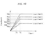
- FIG. 10 is a graph showing the relationship between a flow rate and time at the beginning of the pumping process in the apparatus of FIG. 9;
- FIG. 11 is a schematic view showing a positive displacement type liquid-delivery apparatus according to a sixth embodiment of the present invention.
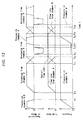
- FIG. 12 is a time chart for a control process performed by the positive displacement type liquid-delivery apparatus of FIG. 11.
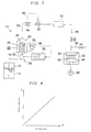
- FIGS. 1 and 2 show a positive displacement liquid-delivery apparatus according to a first embodiment of the present invention.
- a liquid feed tank 12 accommodates a liquid 14, such as a liquid feed.
- a positive displacement pump 10 supplies the liquid 14 from the feed liquid tank 12 to a processing apparatus 16 at a prescribed amount.
- the processing apparatus 16 is a vaporizer that supplies deposition gas via a gas supply line 86 to a CVD reaction chamber 80.
- a gas injection head 82 in the reaction chamber 80 ejects the supplied deposition gas toward a semiconductor wafer W mounted on a base 84.
- the positive displacement liquid-delivery apparatus shown in FIG. 1 also includes an exhaust pump 88 and a vent line 90 for venting the deposition gas.
- the positive displacement pump 10 includes a housing 22 that is approximately cylindrical in shape. One end of the housing 22 is connected to an inlet pipe 18 extending from the feed liquid tank 12, while the other end is connected to an outlet pipe 20 connected to the processing apparatus 16. An opening is formed in the center of the bottom plate of the housing 22. A bellows 24 (diaphragm) is attached to the inner edge of this opening, and extends inwardly and concentrically with the housing 22. The other end of the bellows 24 is hermetically closed by a retaining plate 26. This construction of the housing 22 and bellows 24 forms a liquid-delivery chamber 28 capable of retaining liquid hermetically and varying its capacity. A working space 30 which is open to the air is also formed in the inner side of the bellows 24.
- a diaphragm driving device 36 is provided in the working space 30.
- the diaphragm driving device 36 includes a drive unit 32 having a drive source such as a motor (not shown), and a rod 34 that moves up and down by actuation of the drive unit 32.
- the retaining plate 26 is connected to the top end of the rod 34.
- the drive unit 32 is provided with a conversion mechanism (not shown) for converting rotational movement by the drive source into linear movement with a feed screw mechanism or the like.
- the bellows 24 extends and retracts in the axial direction, thereby changing the capacity of the liquid-delivery chamber 28 to supply a predetermined amount of liquid 14 to the processing apparatus 16.
- a pressure gauge 38 is provided on the housing 22 for measuring the pressure inside the liquid-delivery chamber 28.
- a control valve 40 capable of controlling its opening degree is provided in the outlet pipe 20.
- a signal from the pressure gauge 38 is inputted into the control valve 40.
- the opening degree of the control valve 40 is adjusted based on the signal from the pressure gauge 38 to maintain the pressure P in the liquid-delivery chamber 28 at a constant value that is slightly higher than the pressure P 0 in the working space 30 (atmospheric pressure in this example).
- the control valve 40 and the pressure gauge 38 constitute a differential pressure control unit 42.
- a flow meter 44 is also provided at the upstream side of the control valve 40 in the outlet pipe 20 for measuring the flow rate of liquid flowing in the outlet pipe 20.
- a signal from the flow meter 44 is also inputted into the control valve 40.
- the flow meter 44 and the control valve 40 constitute a flow control unit 46 for controlling the flow rate of liquid supplied to the processing apparatus 16 through the outlet pipe 20.
- the positive displacement liquid-delivery apparatus can switch selectively between control by the differential pressure control unit 42 and control by the flow control unit 46.
- control by the differential pressure control unit 42 is in operation, the control valve 40 is controlled on the basis of signal from the pressure gauge 38 to maintain the differential pressure at a constant value as described above (normal mode). With this control, the discharge flow rate can be accurately and stably maintained.
- the discharge flow rate can be expressed by a function dependent only on the stroke of the diaphragm driving device 36. If a certain flow rate of liquid is being required, then changes in the stroke can be controlled so as to correspond to such flow rate.
- the solid lines describing the bellows 24 in FIG. 2 represent the bellows 24 in a state of equilibrium. If the pressure P in the liquid-delivery chamber 28 increases, and thus the differential pressure ⁇ P increases, then the bellows 24 may deform as shown by the chain double-dashed lines in FIG. 2. Hence, even if the position of the retaining plate 26 does not change, the change in the differential pressure ⁇ P will cause the capacity of the liquid-delivery chamber 28 to change.
- the differential pressure ⁇ P By maintaining the differential pressure ⁇ P at a constant value while operating the bellows 24, it is possible to achieve a stable flow rate control, because variations or pulsations in the flow caused by random deformation of the bellows 24 are suppressed. Accordingly, the position of the retaining plate 26 will correspond to the capacity of the liquid-delivery chamber 28 on a one-on-one basis. Therefore, it is possible to accurately control the discharge flow rate, which is dependent only on the stroke of the diaphragm driving device 36.
- FIG. 3 shows a positive displacement liquid-delivery apparatus according to a second embodiment of the present invention.
- the structure of the positive displacement liquid-delivery apparatus of the second embodiment differs from that of the first embodiment in that the differential pressure control unit 42 in the first embodiment is replaced with a driving device control unit 50 that receives a signal from the pressure gauge 38 to control the movement of the diaphragm driving device 36.
- the relationship between the pressure in the liquid-delivery chamber 28 and the amount of deformation of the bellows 24 is known in advance.
- the driving device control unit 50 moves the diaphragm driving device 36 to cancel deformation in the bellows 24 caused by pressure changes in the liquid-delivery chamber 28, thereby keeping a flow rate of liquid at a constant value.
- the actual discharge flow rate Q discharged from the liquid-delivery chamber 28 can be defined by the following equation, where q is a set flow rate and V is the amount of deformation in the bellows 24 caused by the pressure P in the liquid-delivery chamber 28.
- Q q + (dV/dt)
- the driving device control unit 50 controls the diaphragm driving device 36 to achieve a set flow rate q when the initial set flow rate is q 0 .
- q q 0 - (dV/dP) ⁇ (dP/dt)
- V aP b + d
- dV/dP abP b-1
- dV/dP abP b-1
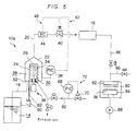
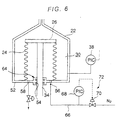
- FIGS. 5 and 6 show a positive displacement liquid-delivery apparatus according to a third embodiment of the present invention.
- a positive displacement pump 10a has a closed system, wherein the working space 30 is not open to the atmosphere. That is, the bottom of the housing 22 is closed by a bottom plate 52.
- the bottom plate 52 has a through-hole 54 through which the rod 34 is inserted, an intake port 56 through which N 2 gas or another pressure regulating gas is introduced, and an exhaust port 58 for exhausting such gas in minute amounts.
- the bottom plate 52 is also provided with a leak fluid tube 62 for discharging liquid that has leaked into the working space 30 and introducing the discharged liquid into a leak sensor 60.
- a seal mechanism 64 is provided in the through-hole 54 to seal the rod 34 hermetically.
- the intake port 56 is connected to a pressure regulating gas source (not shown) by an intake tube 66.
- a pressure sensor 68 for detecting the pressure in the intake tube 66 (equivalent to the pressure in the working space) and a pressure control valve 70 for controlling the pressure in the intake tube 66 based on an output signal from the pressure sensor 68 are provided in the intake tube 66.
- a regulating valve 74 is provided in a line connected to the exhaust port 58 for adjusting a very small amount of exhaust.
- the pressure sensor 68 and the pressure control valve 70 constitute a second differential pressure control unit 72.
- the flow rate from the pressure control valve 70 is defined as Q
- the amount of gas supplied from the pressure control valve 70 when the bellows 24 is stopped is defined as Q 1
- the amount of gas discharged from the regulating valve 74 is defined as Q 2 .
- ⁇ V indicates the change in capacity caused by driving the bellows
- Q Q 2 + ⁇ Q (when the bellows extends)
- Q Q 2 - ⁇ Q (when the bellows retracts)
- Q > 0 not established, control becomes difficult, and hence the following conditions are established.
- Q 2 > ⁇ Q Q 2 Q 1
- Q 1 and Q 2 are set so that the following is established.
- FIG. 7 shows a positive displacement type liquid-delivery apparatus according to a fourth embodiment of the present invention.
- This apparatus includes a positive displacement pump 10 having the same construction as that in the first embodiment, a check valve 100 provided in the outlet pipe 20 that extends from the positive displacement pump 10, and a delivery-liquid pressure sensor 102 for detecting the pressure in the primary side of the check valve 100.
- the apparatus further includes a liquid-delivery chamber pressure sensor 104 for detecting the pressure in the liquid-delivery chamber 28, a control valve 106 disposed upstream of the check valve 100, and a pressure control unit 108 that receives signals from the delivery-liquid pressure sensor 102 and the liquid-delivery chamber pressure sensor 104 and controls the control valve 106 and the drive unit 32 based on these signals. Therefore, the positive displacement type liquid-delivery apparatus of the present embodiment individually controls the pressure in the primary side of the check valve 100 and the pressure in the liquid-delivery chamber 28.
- the pressure in the primary side of the check valve 100 i.e., the pressure of liquid contained in a pipe 110 connecting the check valve 100 and the control valve 106 is controlled to be less than the cracking pressure of the check valve 100, and also controlled to be higher than the vapor pressure of the liquid.
- the pressure in the liquid-delivery chamber 28 is controlled to be at the pressure required for normal pumping operations (hereinafter referred to as operating pressure).
- the pressure in the primary side of the check valve 100 is approximately 1.5 kg/cm 2 ( ⁇ 147 kPa) when, for example, the cracking pressure is 2 kg/cm 2 ( ⁇ 196 kPa) and the vapor pressure of the liquid therein is 0.5 kg/cm 2 ( ⁇ 49 kPa).
- the pressure in the liquid-delivery chamber 28 is approximately 2.5 kg/cm 2 ( ⁇ 245 kPa), for example, which is the same as the operating pressure.
- This method includes the step of driving the drive unit 32 to lower the pressure in the liquid-delivery chamber 28 to the initial pressure in the primary side of the check valve 100, which is 1.5 kg/cm 2 ⁇ 147 kPa) in one example (step 1), and the step of opening the control valve 106 (step 2).
- step 1 the drive unit 32 is driven to set the pressure in the primary side of the check valve 100 equivalent to its initial pressure (step 3), and the control valve 106 is closed (step 4).
- the drive unit 32 is driven to raise the pressure in the liquid-delivery chamber 28 to its initial pressure of 2.5 kg/cm 2 ( ⁇ 245 kPa)(step 5).
- the flow rate of liquid is allowed to be proportional to time when the flow rate is increasing, whereby a set time t s for the flow rate to reach a set flow rate Q s is established and the flow rate can be strictly controlled in the set time t s .
- the pipe 110 connecting the check valve 100 and the control valve 106 is sufficiently short and constructed of a highly rigid material so that there is almost no volume expansion in the pipe 110 even when the pressure therein rises to the same pressure as that in the liquid-delivery chamber 28. Therefore, the pressure in the secondary side of the check valve 100 can be maintained at the operating pressure in order to achieve the required flow rate immediately after the pumping operation begins.
- a flexible tube or the like is used for the pipe 110, volume expansion may occur in the pipe 110 when the pressure therein rises to the same pressure as that in the liquid-delivery chamber 28.
- the pressure in the secondary side of the check valve 100 can be set to the operating pressure immediately after the pumping operation begins by setting the pressure in the liquid-delivery chamber 28 to the pressure (P + ⁇ ), slightly higher than the pressure P during pumping operations, where the pressure ⁇ is equivalent to the estimated amount caused by volume expansion in the pipe 110.
- FIG. 9 shows a positive displacement liquid-delivery apparatus according to the fifth embodiment of the present invention.
- This apparatus comprises a plurality of positive displacement pumps 10 with a similar construction as that in the first embodiment. These positive displacement pumps 10 are arranged in parallel and each of the pumps 10 is capable of delivering liquid of a different type simultaneously to the processing apparatus 16.
- the positive displacement liquid-delivery apparatus includes a plurality of feed lines 112a-112d, wherein each feed line is connected to a positive displacement pump 10 for delivery liquid feed A, B, C and D. These feed lines 112a-112d are joined together in the secondary side of the check valve 100, and then connected to the processing apparatus 16.
- the positive displacement liquid-delivery apparatus controls the pressure in the feed lines 112a-112d in the primary side of the check valve 100 so as not to drop below the vapor pressure of each of the liquid feeds flowing through the respective feed lines 112a-112d.
- the apparatus also controls the pressure in the liquid-delivery chamber 28 of each of the positive displacement pumps 10 at the operating pressure or a pressure higher than the operating pressure by an amount ⁇ determined by estimating the volume expansion in the pipes.
- FIG. 11 shows a positive displacement liquid-delivery apparatus according to a sixth embodiment of the present invention.
- This apparatus comprises two positive displacement pumps 10 with a similar construction as that in the first embodiment.
- the two positive displacement pumps 10 are arranged in parallel and driven to alternately pump the same type of liquid to the processing apparatus 16.
- the outlet pipes 20 extending from the respective positive displacement pumps 10 and having respective control valves 106 join together in the primary side of the check valve 100, and the secondary side of the check valve 100 is connected to the processing apparatus 16.
- liquid-delivery chamber A and control valve A are referred to as liquid-delivery chamber A and control valve A, respectively, while those positioned on the left side of the diagram will be referred to as liquid-delivery chamber B and control valve B, respectively.
- control valves A and B are both closed, the drive unit 32 of each of the positive displacement pumps 10 is driven to bring the pressure in the chambers A and B to the operating pressure (time 0-t 1 ).
- the control valve A is opened to discharge liquid from the liquid-delivery chamber A (time t 2 ).
- the discharge flow rate from the liquid-delivery chamber A is gradually decreased, while at the same time the control valve B is opened to allow liquid to be discharged from the liquid-delivery chamber B.
- the control valve A is closed (time t 3 -t 4 ).
- the flow rate from the pump that began pumping operation is gradually increased, while the flow rate from the pump that is stopping pumping operation is gradually decreased at the same rate such that the overall flow rate does not change.
- the liquid-delivery chamber A is pressurized to raise its pressure back to the operating pressure (time t 7 -t 8 ).
- the discharge flow rate of liquid discharged from the liquid-delivery chamber B is gradually decreased, while simultaneously the control valve A is opened to begin discharging of liquid from the liquid-delivery chamber A.
- the control valve B is closed (time t 9 -t 10 ) and this procedure is repeated.
- the flow rate from the positive displacement pump 10 that starts pumping operation is gradually increased, while the flow rate from the pump that is stopping pumping operation is gradually decreased at the same rate such that the overall flow rate does not change.
- a pipe 114 connecting the check valve 100 and control valve 106 is sufficiently short and constructed of a highly rigid material so that there is almost no volume expansion in the pipe 114 when the pressure therein rises to the same pressure as that in the liquid-delivery chamber 28. Therefore, the pressure in the secondary side of the check valve 100 can be maintained at the operating pressure in order to achieve the required flow rate immediately after pumping operation begins.
- a flexible tube or the like is used for the pipe 114, volume expansion may occur in the pipe 114 when the pressure therein rises to the same pressure as that in the liquid-delivery chamber 28.
- the pressure in the secondary side of the check valve 100 can be raised to the operating pressure immediately after pumping operation begins by setting the pressure in the liquid-delivery chamber 28 to the pressure (P + ⁇ ), slightly higher than the pressure P during pumping operations, where the pressure ⁇ is equivalent to the estimated amount caused by volume expansion in the pipe 114.
- the differential pressure between the inner and outer sides of the diaphragm is controlled at a constant value while the diaphragm is displaced, hence it is possible to provide a compact apparatus capable of delivering liquid with great precision.
- This type of apparatus is very useful in manufacturing processes for semiconductor elements.
- the pressure in the primary side of the check valve is controlled so as not to fall below the vapor pressure of the liquid therein when the pumping operations are stopped. Furthermore, the pressure in the liquid-delivery chamber is maintained at the operating pressure or at a higher pressure. Accordingly, the time required to stabilize pumping operations can be shortened, and it is possible to control the flow rate of liquid immediately after pumping operations begin.
- a positive displacement liquid-delivery apparatus comprising:
- a positive displacement liquid-delivery apparatus as claimed in item 1, wherein said diaphragm comprises a bellows.
- a positive displacement liquid-delivery apparatus as claimed in item 1, wherein atmosphere pressure is applied to one of said both sides of said diaphragm.
- a positive displacement liquid-delivery apparatus as claimed in item 4, further comprising a flow sensor disposed on a discharge path; and wherein control is performed based on a signal from said flow sensor when the pressure in said liquid-delivery chamber during the pumping process exceeds a prescribed value or the absolute value of the rate of pressure variations exceeds a prescribed value.
- a positive displacement liquid-delivery apparatus as claimed in item 1, wherein said liquid-delivery chamber is arranged so as to achieve the required discharge flow volume of said fluid in one stroke.
- a positive displacement liquid-delivery apparatus as claimed in item 1, wherein gas is employed to pressurize the space on the opposite side of said diaphragm from said liquid-delivery chamber.
- a positive displacement liquid-delivery apparatus as claimed in item 1, further comprising a plurality of positive displacement pumps arranged in parallel and delivering different kinds of fluid to a single processing unit.
- a positive displacement liquid-delivery apparatus as claimed in item 1, comprising two positive displacement pumps delivering the same kind of fluid, and alternately delivering said fluid to a single processing unit in a continuous manner.
- a positive displacement liquid-delivery apparatus comprising:
- a positive displacement liquid-delivery apparatus as claimed in item 10, wherein gas is employed to pressurize the space on the opposite side of said diaphragm from said liquid-delivery chamber.
- a positive displacement liquid-delivery apparatus as claimed in item 10 comprising two positive displacement pumps delivering the same kind of fluid, and alternately delivering said fluid to a single processing unit in a continuous manner.
- a positive displacement liquid-delivery apparatus comprising:
- a positive displacement liquid-delivery apparatus as claimed in item 15, wherein said pressure control unit comprises a control valve disposed upstream of said check valve, and regulates the pressure in said liquid-delivery chamber during pump stoppage at the pressure required for pumping operation.
- a positive displacement liquid-delivery apparatus as claimed in item 15, wherein said pressure control unit comprises a control valve disposed upstream of said check valve, and regulates the pressure in said liquid-delivery chamber during pump stoppage at the pressure higher than the pressure required for pumping operation by an amount equivalent to the estimated amount caused by the volume expansion of the piping between the check valve and control valve.
- a positive displacement liquid-delivery apparatus as claimed in item 15, wherein gas is employed to pressurize the space on the opposite side of said diaphragm from said liquid-delivery chamber.
- a positive displacement liquid-delivery apparatus as claimed in item 15, comprising two positive displacement pumps delivering the same kind of fluid, and alternately delivering said fluid to a single processing unit in a continuous manner.
- a deposition apparatus comprising:
- a deposition apparatus comprising:
- a deposition apparatus comprising:
Abstract
Description
- The present invention relates to a positive displacement type liquid-delivery apparatus that can be used to deliver a very small amount of liquid at a constant rate to various processing apparatuses such as a chemical vapor deposition apparatus. Description of the Related Arts:
- Recently, in the semiconductor manufacturing industry, the integration of integrated circuits has been improved remarkably, and the research and development activities of DRAM are being intensively carried out in anticipation of gigabit order DRAMs which will replace current megabit order DRAMs. The capacitor element having a large capacity per unit area is needed to produce such DRAMs. As a dielectric thin-film material for producing elements having such a large capacity per unit area, a metallic oxide film material such as tantalum pentaoxide (Ta2O5) having dielectric constant of approximately 20, or barium titanate (BaTiO3) or strontium titanate (SrTiO3) or barium strontium titanate having dielectric constant of approximately 300 is considered to be a promising thin-film material.
- To deposit such a metallic oxide film material on a substrate in a vapor phase, a gaseous mixture made by mixing one or more gas feed materials of organometallic compounds and an oxygen containing gas is ejected to a substrate heated to a certain temperature. Organometallic gaseous feed material is chosen by the nature of the thin film to be produced. For example, a metallic oxide film comprised by barium strontium titanate is produced by first converting Ba, Sr, Ti or their compounds into their dipivaloylmethane (DPM) compounds, and dissolving these compounds in an organic solvent such as tetrahydrofuran (THF) to produce respective liquid feed materials. After uniformly mixing these liquid feed materials in a required proportion to produce a master liquid feed, such master liquid feed is sent to a vaporizer to produce a gaseous feed for use in the chemical vapor deposition apparatus.
- Such master liquid feed is extremely susceptible to degradation even in a sealed container, and therefore it is undesirable to have such a master liquid feed stagnate inside delivery piping. The master liquid feed is especially susceptible to producing precipitate particles, by being heated or being exposed to air, which tend to produce inferior quality films. Therefore, once the component liquids are mixed into a master liquid feed, it is necessary that the master liquid feed be maintained in a stable condition. It is also desirable that the master liquid feed be completely used up as quickly as practicable. Furthermore, it is desirable that the film deposition apparatus be capable of exercising a fine control of the flow rate of the master liquid feed over a wide range of flow rates from a very small flow rate to a large flow rate. Therefore, the liquid-delivering apparatus should be capable of providing a stringent control of the flow rates of the liquid feed.
- As a positive displacement type liquid-delivering apparatus used in these applications, there has been known such an apparatus in which a mass flow controller (MFC) is provided in the piping connecting a feed liquid tank and a processing apparatus such as a vaporizer, and the feed liquid tank is pressurized with gas or the like to deliver liquid and a control valve on the MFC is adjusted to control a delivery rate of liquid. Positive displacement pumps incorporating pistons, diaphragms, and the like are also used.
- In general, conventional apparatuses using a mass flow controller have a poor reproducibility of flow control near the lower limit of the allowable control range. Moreover, when the pressure in the processing apparatus increases, a pressure exceeding the pressure in the processing apparatus must be applied to the feed liquid tank side. Hence, a large amount of gas used for pressurizing is dissolved in the liquid in the feed liquid tank, and this dissolved gas is released downstream of the control valve of the mass flow controller or causes surge or pulsation in the flow of the liquid feed.
- Although a positive displacement pump can overcome these drawbacks, a piston pump cannot be used because the sliding parts of the pump generate particles that contaminate the liquid. The positive displacement pumps employing bellows or diaphragms do not contaminate the liquid, but present the following problems.
- It is conceivable to construct such a positive displacement pump in which a container is partitioned by a diaphragm into two chambers, i.e., a liquid delivery chamber and a working fluid chamber, and an incompressible liquid is used as a working fluid. With this construction, the diaphragm moves according to the amount of the working fluid supplied to the working fluid chamber for thereby discharging liquid from the container. Therefore, the precision in controlling the flow rate is more or less dependent on the precision of the external driving system. As a result, an external device is required for pumping the working fluid, and hence troublesome handling of the working fluid is necessary and the overall apparatus becomes large-sized.
- If a driving device for driving the diaphragm is constructed mechanically, then these problems are eliminated and the overall apparatus becomes simple. However, it is very difficult to control the movement of the diaphragm so as to keep the deliver liquid at a constant rate if the processing conditions (pressure) in the secondary side (downstream side) of the container vary. Installing a flow meter in the secondary side of the container for performing feedback control, it is not possible to obtain a better performance than that of the mass flow controller, because a precision and reproducibility of the flow meter is the same level as the mass flow controller.
- When the liquid-delivery is stopped, the pressure in the secondary side of the positive displacement pump slowly decreases due to a small leak in the check valve provided in the primary side (upstream side) of the processing apparatus (the part to which liquid is supplied). This may lead to a pressure drop when the liquid-delivery resumes, requiring time to stabilize the flow rate of liquid and potentially causing other problems. For example, if the pressure in the processing apparatus is below atmospheric pressure, the liquid feed may be vaporized because the pressure in the primary side of the check valve drops below the vapor pressure of the liquid feed.
- Further, in the positive displacement pump, pressure variations occur in piping in the secondary side of the pump when the pumping operation begins, and hence the flow rate of liquid cannot be controlled until the liquid-delivery is stabilized. If a plurality of liquid feeds are required to be delivered at the same ratio, for example, these liquid feeds cannot be used until the liquid-delivery is stabilized.
- In view of the foregoing, it is an object of the present invention to provide a positive displacement type liquid-delivery apparatus employing a positive displacement pump with a flexible diaphragm which can supply liquid at a constant rate with high precision and high reproducibility, shorten the time required to stabilize the liquid-delivery from starting of pumping operation, and control the flow rate of liquid immediately after the pumping operation begins.
- According to an aspect of the present invention, there is provided a positive displacement liquid-delivery apparatus comprising: a positive displacement pump comprising a housing having a liquid-delivery chamber divided by a flexible diaphragm and a diaphragm driving unit linked to the diaphragm to discharge fluid from the liquid-delivery chamber; and a differential pressure control unit for controlling the differential pressure between both sides of the diaphragm at a constant value during the pumping process.
- Accordingly, the construction of the apparatus is simplified because the diaphragm is driven directly by the diaphragm driving unit. Further, by keeping the differential pressure between both sides of the diaphragm at a constant value, it is possible to keep the diaphragm at a constant amount of deformation, thus eliminating error caused by the diaphragm deformation. Hence, the diaphragm driving unit can control the amount of deformation in the diaphragm to perform precise flow rate control.
- In a preferred aspect of the present invention, the differential pressure control unit comprises a differential pressure sensor for detecting the differential pressure between both sides of the diaphragm, and a control valve for controlling the flow rate of the liquid discharged from the liquid-delivery chamber on a basis of a signal from the differential pressure sensor. In other words, the differential pressure of the diaphragm is controlled so as to be constant, thus causing the flow rate of liquid to be controlled indirectly.
- Accordingly, it is possible to adjust the pressure in the liquid-delivery chamber indirectly by adjusting the control valve. If there is sufficiently low pressure variation, the space on the opposite side of the diaphragm from the liquid-delivery chamber, such as atmospheric pressure, the pressure sensor is required to be used only the space on the side facing the liquid-delivery chamber.
- In this case, a predetermined amount of liquid is not exactly delivered at the secondary side of the diaphragm in accordance with the moving distance of the diaphragm. In a strict sense, when the differential pressure of the both sides of the diaphragm varies, the amount of deformation of the diaphragm varies in accordance with the differential pressure, and hence the delivery amount of liquid is deviated from the predetermined amount of liquid. Therefore, it is necessary to control the differential pressure of the diaphragm at a constant value. For example, if the relationship between the position of the diaphragm and the amount of delivery liquid at a predetermined differential pressure is found, and the differential pressure of the diaphragm is controlled so as to be equal to the predetermined differential pressure when it is actually used, then the amount of delivery liquid corresponds to the amount of deformation of the diaphragm at the differential pressure. Since the amount of delivery liquid is estimated from the relationship between the position of the diaphragm and the differential pressure, a predetermined amount of delivery liquid can be exactly obtained.
- In a preferred aspect of the present invention, a flow sensor is disposed on a discharge path and control is performed based on a signal from the flow sensor when the pressure in the liquid-delivery chamber during the pumping process exceeds a prescribed value or the absolute value of the rate of pressure variations exceeds a prescribed value.
- With this construction, precise control can be preformed even with severe variations in the system conditions.
- In a preferred aspect of the present invention, the liquid-delivery chamber is arranged so as to achieve the required discharge flow volume of the fluid in one stroke.
- With this construction, the bellows operation is always stable and uniform for each process, thereby avoiding pressure and flow rate variations, for example, that occur when switching valves in alternate operations. Performing one pump operation using only a portion of one stroke can further increase the life of the bellows.
- In this case, the required discharge flow volume of the fluid is such volume that a predetermined film is formed on one substrate (semiconductor wafer) in one stroke, or more than such volume.
- In a preferred aspect of the present invention, the gas is employed to pressurize the space on the opposite side of the diaphragm from the liquid-delivery chamber.
- Generally speaking, the diaphragm itself has an allowable differential pressure between the both sides of the bellows. When this differential pressure is small or the pressure required in the processing apparatus on the secondary side of the pump is larger than the allowable differential pressure, liquid-delivery cannot be performed if the pressure on the side of the diaphragm opposite from the liquid-delivery is atmospheric pressure. However, it is possible to keep the differential pressure low by pressurizing this side opposite the liquid-delivery chamber with a gas in order to maintain the differential pressure within the tolerable level for pumping operations.
- When the gas is charged, the pressure at the primary side of the diaphragm fluctuates. However, in such a condition, it is desirable to make the differential pressure of the diaphragm constant by the control valve.
- Since the differential pressure of the diaphragm must be maintained at a constant value as described above in order to supply the fluid at a constant flow rate, the gas pressure P must also be constant. In the example described above, the volume V on the side of the diaphragm opposite the liquid-delivery chamber varies during pumping operations. Accordingly, the side of the diaphragm opposite the liquid-delivery chamber should be supplied with an amount of gas based on the liquid-delivery amount ΔV, that is, ΔV × P.
- The method of controlling the differential pressure both sides of the diaphragm can be applied for using the pressure of the gas and the liquid, and controlling the pressure on the gas side. However, the injection and discharge of gas requires some time, resulting in control delays when pressure variations occur abruptly. Hence, variations in the differential pressure may occur more frequently, making it difficult to maintain a prescribed amount of liquid. Still, this method may be suitable for processes that have no severe pressure variations.
- A leak sensor can be provided in the space opposite the liquid-delivery chamber for detecting fluid leaking caused by breakage in the diaphragm. With this arrangement, breakage in the diaphragm can be detected. If the side opposite the liquid-delivery chamber is also filled with liquid for driving the diaphragm, it is extremely difficult to detect breakage in the diaphragm. In the event that the diaphragm breaks, liquid for driving the diaphragm is mixed with the liquid to be pumped and the mixture is pumped together. Since the amount of liquid discharged from the apparatus does not vary, the breakage cannot be detected on a flow rate monitor.
- In the present invention, however, breakage in the diaphragm can be detected by providing a relief discharge port, for example, on the gas side of the diaphragm and a relief sensor in the relief discharge port or on the secondary side. Further, it is possible to prevent gas from mixing with the pump side by always keeping the gas side at a lower pressure than the pump side. Hence, the present invention can avoid the problem of pumping liquid that mixes with driving liquid when the diaphragm breaks. Such problem is common to conventional apparatus with fluid-driven diaphragms.
- In a preferred aspect of the present invention, a plurality of positive displacement pumps is arranged in parallel and delivering different kinds of fluid to a single processing unit.
- In a preferred aspect of the present invention, two positive displacement pumps are delivering the same kind of fluid, and alternately delivering the fluid to a single processing unit in a continuous manner.
- In a preferred aspect of the present invention, a housing having a liquid-delivery chamber is divided by a flexible diaphragm and a diaphragm driving unit linked to said diaphragm to discharge fluid from said liquid-delivery chamber; and said diaphragm driving unit drives said diaphragm to maintain the flow rate of said liquid discharged from said liquid-delivery chamber at a constant rate based on the variation of the differential pressure between both sides of the diaphragm.
- In a preferred aspect of the present invention, the liquid-delivery chamber is arranged so as to achieve the required discharge flow volume of the fluid in one stroke.
- In a preferred aspect of the present invention, the gas is employed to pressurize the space on the opposite side of the diaphragm from the liquid-delivery chamber.
- In a preferred aspect of the present invention, a plurality of positive displacement pumps is arranged in parallel and delivering different kinds of fluid to a single processing unit.
- In a preferred aspect of the present invention, two positive displacement pumps are delivering the same kind of fluid, and alternately delivering said fluid to a single processing unit in a continuous manner.
- According to an aspect of the present invention, there is provided a positive displacement liquid-delivery apparatus comprising: a positive displacement pump comprising a housing having a liquid-delivery chamber divided by a flexible diaphragm and a diaphragm driving unit linked to the diaphragm to discharge fluid from the liquid-delivery chamber; and an discharge path extending from the liquid-delivery chamber; a check valve disposed on the discharge path; and a pressure control unit for controlling the primary side pressure of the check valve so as not to drop below the vapor pressure of the fluid discharged from the liquid-delivery chamber during stoppage of the pumping process.
- With this construction, it is possible to prevent a drop in pressure on the primary side of the check valve caused by a leak from the check valve and the generation of voids caused by vaporization.
- In a preferred aspect of the present invention, the pressure control unit comprises a control valve disposed upstream of the check valve, and regulates the pressure in the liquid-delivery chamber during pump stoppage at the pressure required for pumping operation.
- With this construction, if the pipe connecting the check valve and control valve is sufficiently short and formed of a highly rigid material and there is almost no volume expansion in this section of pipe when its internal pressure rises at the beginning of the pumping process, it is possible to set the pressure in the secondary side of the check valve to the normal pressure for pumping immediately after pumping begins in order to pump a prescribed flow rate without any time lag.
- In a preferred aspect of the present invention, the pressure control unit comprises a control valve disposed upstream of the check valve, and regulates the pressure in the liquid-delivery chamber during pump stoppage at the pressure higher than the pressure required for pumping operation by an amount equivalent to the estimated amount caused by the volume expansion of the piping between the check valve and control valve.
- With this construction, if this section of pipe is a flexible pipe with low rigidity and there is volume expansion in the pipe when the pressure rises at the beginning of the pumping process, it is possible to set the pressure in the secondary side of the check valve to the normal pressure for pumping immediately after pumping begins in order to pump a prescribed flow rate without any time lag.
- In a preferred aspect of the present invention, the liquid-delivery chamber is arranged so as to achieve the required discharge flow volume of the fluid in one stroke.
- In a preferred aspect of the present invention, the gas is employed to pressurize the space on the opposite side of the diaphragm from the liquid-delivery chamber.
- In a preferred aspect of the present invention, a plurality of positive displacement pumps is arranged in parallel and delivering different kinds of fluid to a single processing unit.
- With this construction, the apparatus can individually control a different flow rate of fluid discharged from each positive displacement pump from the moment the pumping process begins, thereby always pumping the same proportion of fluids to the single process device.
- In a preferred aspect of the present invention, two positive displacement pumps delivering the same kind of fluid, and alternately delivering the fluid to a single processing unit in a continuous manner.
- With this construction, it is possible to operate both pumps alternately such that the first pump gradually pumps a larger flow rate after the start of operations and the second pump gradually pumps a decreasing amount in order that the overall flow rate does not change. Accordingly, the same liquid can be supplied continuously to the single process device without variation in flow.
- According to an aspect of the present invention, there is provided a deposition apparatus comprising: a vaporizer for vaporizing a fluid feed supplied from the positive displacement liquid-delivery apparatus; and a deposition chamber in which thin films are deposited using the feed gas supplied from the vaporizer.
- The above and other objects, features, and advantages of the present invention will become apparent from the following description when taken in conjunction with the accompanying drawings which illustrate preferred embodiments of the present invention by way of example.
- FIG. 1 is a schematic view showing a positive displacement type liquid-delivery apparatus according to a first embodiment of the present invention;
- FIG. 2 is an enlarged view showing part of the positive displacement type liquid-delivery apparatus of FIG. 4;
- FIG. 3 is a schematic view showing a positive displacement liquid-delivery apparatus according to a second embodiment of the present invention;
- FIG. 4 is a graph showing the relationship between the pressure in the liquid delivery chamber and deformation of the bellows according to the second embodiment of the present invention;
- FIG. 5 is a schematic view showing a positive displacement type liquid-delivery apparatus according to a third embodiment of the present invention;
- FIG. 6 is an enlarged cross-sectional view showing part of the positive displacement type liquid-delivery apparatus of FIG. 5;
- FIG. 7 is a schematic view showing a positive displacement type liquid-delivery apparatus according to a fourth embodiment of the present invention;
- FIG. 8 is a graph showing the relationship between a flow rate and time at the beginning of the pumping process in the apparatus of FIG. 7;
- FIG. 9 is a schematic view showing a positive displacement type liquid-delivery apparatus according to a fifth embodiment of the present invention;
- FIG. 10 is a graph showing the relationship between a flow rate and time at the beginning of the pumping process in the apparatus of FIG. 9;
- FIG. 11 is a schematic view showing a positive displacement type liquid-delivery apparatus according to a sixth embodiment of the present invention; and
- FIG. 12 is a time chart for a control process performed by the positive displacement type liquid-delivery apparatus of FIG. 11.
- FIGS. 1 and 2 show a positive displacement liquid-delivery apparatus according to a first embodiment of the present invention. In this positive displacement liquid-delivery apparatus, a liquid feed tank 12 accommodates a liquid 14, such as a liquid feed. A positive displacement pump 10 supplies the liquid 14 from the feed liquid tank 12 to a processing apparatus 16 at a prescribed amount. In this example, the processing apparatus 16 is a vaporizer that supplies deposition gas via a gas supply line 86 to a CVD reaction chamber 80. A gas injection head 82 in the reaction chamber 80 ejects the supplied deposition gas toward a semiconductor wafer W mounted on a base 84. The positive displacement liquid-delivery apparatus shown in FIG. 1 also includes an exhaust pump 88 and a vent line 90 for venting the deposition gas.
- The positive displacement pump 10 includes a housing 22 that is approximately cylindrical in shape. One end of the housing 22 is connected to an inlet pipe 18 extending from the feed liquid tank 12, while the other end is connected to an outlet pipe 20 connected to the processing apparatus 16. An opening is formed in the center of the bottom plate of the housing 22. A bellows 24 (diaphragm) is attached to the inner edge of this opening, and extends inwardly and concentrically with the housing 22. The other end of the bellows 24 is hermetically closed by a retaining plate 26. This construction of the housing 22 and bellows 24 forms a liquid-delivery chamber 28 capable of retaining liquid hermetically and varying its capacity. A working space 30 which is open to the air is also formed in the inner side of the bellows 24.
- A diaphragm driving device 36 is provided in the working space 30. The diaphragm driving device 36 includes a drive unit 32 having a drive source such as a motor (not shown), and a rod 34 that moves up and down by actuation of the drive unit 32. The retaining plate 26 is connected to the top end of the rod 34. The drive unit 32 is provided with a conversion mechanism (not shown) for converting rotational movement by the drive source into linear movement with a feed screw mechanism or the like. When the drive unit 32 is operated, the bellows 24 extends and retracts in the axial direction, thereby changing the capacity of the liquid-delivery chamber 28 to supply a predetermined amount of liquid 14 to the processing apparatus 16.
- A pressure gauge 38 is provided on the housing 22 for measuring the pressure inside the liquid-delivery chamber 28. A control valve 40 capable of controlling its opening degree is provided in the outlet pipe 20. A signal from the pressure gauge 38 is inputted into the control valve 40. The opening degree of the control valve 40 is adjusted based on the signal from the pressure gauge 38 to maintain the pressure P in the liquid-delivery chamber 28 at a constant value that is slightly higher than the pressure P0 in the working space 30 (atmospheric pressure in this example). The control valve 40 and the pressure gauge 38 constitute a differential pressure control unit 42.
- A flow meter 44 is also provided at the upstream side of the control valve 40 in the outlet pipe 20 for measuring the flow rate of liquid flowing in the outlet pipe 20. A signal from the flow meter 44 is also inputted into the control valve 40. Hence, the flow meter 44 and the control valve 40 constitute a flow control unit 46 for controlling the flow rate of liquid supplied to the processing apparatus 16 through the outlet pipe 20.
- With this construction, the positive displacement liquid-delivery apparatus can switch selectively between control by the differential pressure control unit 42 and control by the flow control unit 46. Normally, control by the differential pressure control unit 42 is in operation, the control valve 40 is controlled on the basis of signal from the pressure gauge 38 to maintain the differential pressure at a constant value as described above (normal mode). With this control, the discharge flow rate can be accurately and stably maintained.
- This process will be described with reference to FIG. 2. If the bellows 24 is deformed at a constant rate, then the discharge flow rate can be expressed by a function dependent only on the stroke of the diaphragm driving device 36. If a certain flow rate of liquid is being required, then changes in the stroke can be controlled so as to correspond to such flow rate.
- However, because the bellows 24 is flexible by nature, the bellows 24 is deformed locally by a differential pressure ΔP between the pressure P in the liquid-delivery chamber 28 and the pressure P0 in the working space 30 ( ΔP = P - P0), in addition to the deformation caused by tensile force from the retaining plate 26. The solid lines describing the bellows 24 in FIG. 2 represent the bellows 24 in a state of equilibrium. If the pressure P in the liquid-delivery chamber 28 increases, and thus the differential pressure ΔP increases, then the bellows 24 may deform as shown by the chain double-dashed lines in FIG. 2. Hence, even if the position of the retaining plate 26 does not change, the change in the differential pressure ΔP will cause the capacity of the liquid-delivery chamber 28 to change.
- By maintaining the differential pressure ΔP at a constant value while operating the bellows 24, it is possible to achieve a stable flow rate control, because variations or pulsations in the flow caused by random deformation of the bellows 24 are suppressed. Accordingly, the position of the retaining plate 26 will correspond to the capacity of the liquid-delivery chamber 28 on a one-on-one basis. Therefore, it is possible to accurately control the discharge flow rate, which is dependent only on the stroke of the diaphragm driving device 36.
- In some cases, it is not possible to adjust the flow rate of liquid by simply monitoring the differential pressure with the pressure gauge and controlling the stroke on the basis of the differential pressure. In the pressure gauge that detects pressure by sensing the amount of deformation in an internal diaphragm or the like, when pressure variations are detected, the bellows have already deformed and a change in flow rate has already occurred. In the present embodiment, therefore, when the pressure inside the liquid-delivery chamber 28 exceeds a predetermined value, or the absolute value of the rate of pressure change exceeds a predetermined value, it is determined that the system is in a fluctuation state. At this time, control is switched from monitoring the differential pressure with the pressure gauge 38 to monitoring the flow rate with the flow rate meter 44. This specific arrangement enables the apparatus to maintain a precise flow rate of liquid even under unstable conditions.
- FIG. 3 shows a positive displacement liquid-delivery apparatus according to a second embodiment of the present invention. The structure of the positive displacement liquid-delivery apparatus of the second embodiment differs from that of the first embodiment in that the differential pressure control unit 42 in the first embodiment is replaced with a driving device control unit 50 that receives a signal from the pressure gauge 38 to control the movement of the diaphragm driving device 36.
- In this embodiment, the relationship between the pressure in the liquid-delivery chamber 28 and the amount of deformation of the bellows 24 is known in advance. The driving device control unit 50 moves the diaphragm driving device 36 to cancel deformation in the bellows 24 caused by pressure changes in the liquid-delivery chamber 28, thereby keeping a flow rate of liquid at a constant value.
- The actual discharge flow rate Q discharged from the liquid-delivery chamber 28 can be defined by the following equation, where q is a set flow rate and V is the amount of deformation in the bellows 24 caused by the pressure P in the liquid-delivery chamber 28.
- As an example, in the case where the amount of deformation V in the bellows 24 and the pressure P in the liquid-delivery chamber 28 have the following relationship,
- As shown in FIG. 4, it can be seen that the dV/dP relationship is of a direct proportion. Therefore, the equation (2) can be simplified to:
- FIGS. 5 and 6 show a positive displacement liquid-delivery apparatus according to a third embodiment of the present invention. In this embodiment, a positive displacement pump 10a has a closed system, wherein the working space 30 is not open to the atmosphere. That is, the bottom of the housing 22 is closed by a bottom plate 52. The bottom plate 52 has a through-hole 54 through which the rod 34 is inserted, an intake port 56 through which N2 gas or another pressure regulating gas is introduced, and an exhaust port 58 for exhausting such gas in minute amounts. The bottom plate 52 is also provided with a leak fluid tube 62 for discharging liquid that has leaked into the working space 30 and introducing the discharged liquid into a leak sensor 60. A seal mechanism 64 is provided in the through-hole 54 to seal the rod 34 hermetically.
- The intake port 56 is connected to a pressure regulating gas source (not shown) by an intake tube 66. A pressure sensor 68 for detecting the pressure in the intake tube 66 (equivalent to the pressure in the working space) and a pressure control valve 70 for controlling the pressure in the intake tube 66 based on an output signal from the pressure sensor 68 are provided in the intake tube 66. A regulating valve 74 is provided in a line connected to the exhaust port 58 for adjusting a very small amount of exhaust. By setting the opening degree of the regulating valve 74 to a certain value and operating the pressure control valve 70 on the basis of the output signal from the pressure sensor 68, it is possible to cancel variations in pressure due to displacement of the bellows 24 and maintain the pressure P1 in the working space 30 at a constant value. The pressure sensor 68 and the pressure control valve 70 constitute a second differential pressure control unit 72.
- Here, the flow rate from the pressure control valve 70 is defined as Q, the amount of gas supplied from the pressure control valve 70 when the bellows 24 is stopped is defined as Q1, and the amount of gas discharged from the regulating valve 74 is defined as Q2. Further, ΔV indicates the change in capacity caused by driving the bellows, and ΔQ = P1ΔV indicates the change in supplied gas followed by this capacity change Δ V. Accordingly,
- By employing the controlling method described above, it is possible to maintain a flow rate of liquid at a desired value even when the delivery pressure of liquid increases due to clogging in the processing apparatus 16 at the downstream side, for example. It is also possible to perform a simple control process using only pressure regulating gas with this construction. However, as in the example of the first embodiment, this method would not be able to cope with abrupt changes in pressure.
- In the event that the bellows 24 is damaged, and a hole or the like is formed in the embodiment described above, liquid leaking through the bellows 24 flows through the leak fluid tube 62 and reaches the leak sensor 60, where the leak will be detected. Accordingly, an appropriate action such as a warning alarm or an automatic pump shutdown procedure will be performed based on an output signal from this leak sensor 60 to prevent an accident from occurring.
- FIG. 7 shows a positive displacement type liquid-delivery apparatus according to a fourth embodiment of the present invention. This apparatus includes a positive displacement pump 10 having the same construction as that in the first embodiment, a check valve 100 provided in the outlet pipe 20 that extends from the positive displacement pump 10, and a delivery-liquid pressure sensor 102 for detecting the pressure in the primary side of the check valve 100. The apparatus further includes a liquid-delivery chamber pressure sensor 104 for detecting the pressure in the liquid-delivery chamber 28, a control valve 106 disposed upstream of the check valve 100, and a pressure control unit 108 that receives signals from the delivery-liquid pressure sensor 102 and the liquid-delivery chamber pressure sensor 104 and controls the control valve 106 and the drive unit 32 based on these signals. Therefore, the positive displacement type liquid-delivery apparatus of the present embodiment individually controls the pressure in the primary side of the check valve 100 and the pressure in the liquid-delivery chamber 28.
- During a stoppage of delivery liquid with the positive displacement type liquid-delivery apparatus of the present embodiment, the pressure in the primary side of the check valve 100, i.e., the pressure of liquid contained in a pipe 110 connecting the check valve 100 and the control valve 106 is controlled to be less than the cracking pressure of the check valve 100, and also controlled to be higher than the vapor pressure of the liquid. Also, the pressure in the liquid-delivery chamber 28 is controlled to be at the pressure required for normal pumping operations (hereinafter referred to as operating pressure).
- At this time, the pressure in the primary side of the check valve 100 is approximately 1.5 kg/cm2 (≒ 147 kPa) when, for example, the cracking pressure is 2 kg/cm2 (≒ 196 kPa) and the vapor pressure of the liquid therein is 0.5 kg/cm2 (≒ 49 kPa). In addition, the pressure in the liquid-delivery chamber 28 is approximately 2.5 kg/cm2 (≒ 245 kPa), for example, which is the same as the operating pressure.
- Even if the pressure in the primary side of the check valve 100 drops due to a leak in the check valve 100, this pressure is controlled so as to be prevented from dropping below the vapor pressure of the liquid. This method includes the step of driving the drive unit 32 to lower the pressure in the liquid-delivery chamber 28 to the initial pressure in the primary side of the check valve 100, which is 1.5 kg/cm2 ≒ 147 kPa) in one example (step 1), and the step of opening the control valve 106 (step 2). Next, the drive unit 32 is driven to set the pressure in the primary side of the check valve 100 equivalent to its initial pressure (step 3), and the control valve 106 is closed (step 4). Subsequently, the drive unit 32 is driven to raise the pressure in the liquid-delivery chamber 28 to its initial pressure of 2.5 kg/cm2 (≒245 kPa)(step 5).
- If a pump drive signal is received during this operation, the entire system is put on standby until the operation is completed. After completion of this operation, the pump can be driven to control the entire system. This procedure will not cause a delay in the process since it only takes 10-15 seconds to complete.
- Lowering the pressure in the primary side of the check valve 100 greatly decreases leaking of the check valve 100. Moreover, by preventing the pressure from dropping below the vapor pressure of the liquid, it is possible to eliminate the generation of voids in the pipe 110. It is also possible to prevent such a condition that a predetermined flow rate of fluid cannot be discharged until the voids disappear and the pressure of liquid exceeds, at least, the cracking pressure of the check valve 100.
- It is desirable to set the pressure in the liquid-delivery chamber 28 to the same pressure in the primary side of the check valve 100 in order to prevent leaking in the check valve 100. However, it takes a considerable amount of time after starting the pump to raise the pressure in the liquid delivery chamber 28 high enough to meet the required flow rate. Therefore, by setting the pressure in the liquid-delivery chamber 28 equivalent to that of the operating pressure, it is possible to discharge the required flow of fluid immediately after the pumping operation begins, without time lag.
- Specifically, by delivering liquid under a constant pressure at all times immediately after the pumping operation begins, as shown in FIG. 8, the flow rate of liquid is allowed to be proportional to time when the flow rate is increasing, whereby a set time ts for the flow rate to reach a set flow rate Qs is established and the flow rate can be strictly controlled in the set time ts.
- In this example, the pipe 110 connecting the check valve 100 and the control valve 106 is sufficiently short and constructed of a highly rigid material so that there is almost no volume expansion in the pipe 110 even when the pressure therein rises to the same pressure as that in the liquid-delivery chamber 28. Therefore, the pressure in the secondary side of the check valve 100 can be maintained at the operating pressure in order to achieve the required flow rate immediately after the pumping operation begins. However, if a flexible tube or the like is used for the pipe 110, volume expansion may occur in the pipe 110 when the pressure therein rises to the same pressure as that in the liquid-delivery chamber 28. In this case, the pressure in the secondary side of the check valve 100 can be set to the operating pressure immediately after the pumping operation begins by setting the pressure in the liquid-delivery chamber 28 to the pressure (P + α), slightly higher than the pressure P during pumping operations, where the pressure α is equivalent to the estimated amount caused by volume expansion in the pipe 110.
- FIG. 9 shows a positive displacement liquid-delivery apparatus according to the fifth embodiment of the present invention. This apparatus comprises a plurality of positive displacement pumps 10 with a similar construction as that in the first embodiment. These positive displacement pumps 10 are arranged in parallel and each of the pumps 10 is capable of delivering liquid of a different type simultaneously to the processing apparatus 16. In this example, the positive displacement liquid-delivery apparatus includes a plurality of feed lines 112a-112d, wherein each feed line is connected to a positive displacement pump 10 for delivery liquid feed A, B, C and D. These feed lines 112a-112d are joined together in the secondary side of the check valve 100, and then connected to the processing apparatus 16.
- In the present embodiment, the positive displacement liquid-delivery apparatus controls the pressure in the feed lines 112a-112d in the primary side of the check valve 100 so as not to drop below the vapor pressure of each of the liquid feeds flowing through the respective feed lines 112a-112d. The apparatus also controls the pressure in the liquid-delivery chamber 28 of each of the positive displacement pumps 10 at the operating pressure or a pressure higher than the operating pressure by an amount α determined by estimating the volume expansion in the pipes. Hence, by setting a constant set time ts for each of the liquid feeds A, B, C and D to reach a set flow rate QAS, QDS, QCS and QDS as shown in FIG. 10, at any arbitrary time t0 within this set time ts, the proportion of flows QAO, QBO, QCO and QDO for the liquid feeds A-D is equivalent to the proportion of set flows QAS-QDS (QA0 : QB0 : QC0 : QD0 = QAS : QBS : QCS : QDS). Hence, it is possible to control the total mixture ratio immediately after the pumping process begins such that the fluid delivered to the processing apparatus 16 always has the same ratio of liquid feeds. This method eliminates such problem that the liquid feeds cannot be used until the pumping operation is stabilized.
- FIG. 11 shows a positive displacement liquid-delivery apparatus according to a sixth embodiment of the present invention. This apparatus comprises two positive displacement pumps 10 with a similar construction as that in the first embodiment. The two positive displacement pumps 10 are arranged in parallel and driven to alternately pump the same type of liquid to the processing apparatus 16. In other words, the outlet pipes 20 extending from the respective positive displacement pumps 10 and having respective control valves 106 join together in the primary side of the check valve 100, and the secondary side of the check valve 100 is connected to the processing apparatus 16.
- An example of control conducted by the apparatus of the sixth embodiment will be described with reference to FIG. 12. For purposes of explanation, the liquid-delivery chamber 28 and the control valve 106 positioned on the right side of FIG. 11 will be referred to as liquid-delivery chamber A and control valve A, respectively, while those positioned on the left side of the diagram will be referred to as liquid-delivery chamber B and control valve B, respectively.
- While control valves A and B are both closed, the drive unit 32 of each of the positive displacement pumps 10 is driven to bring the pressure in the chambers A and B to the operating pressure (time 0-t1). Based on a pump start signal, the control valve A is opened to discharge liquid from the liquid-delivery chamber A (time t2). After a predetermined interval elapses, the discharge flow rate from the liquid-delivery chamber A is gradually decreased, while at the same time the control valve B is opened to allow liquid to be discharged from the liquid-delivery chamber B. When the flow rate of liquid discharged from the liquid-delivery chamber B reaches a set flow rate, the control valve A is closed (time t3-t4). During this time, the flow rate from the pump that began pumping operation is gradually increased, while the flow rate from the pump that is stopping pumping operation is gradually decreased at the same rate such that the overall flow rate does not change. By alternating operations between two pumps, the same amount of feed fluid can be delivered continuously to the processing apparatus 16 without variation in the flow rate.
- After the liquid-delivery chamber A is aspirated (time t5-t6), the liquid-delivery chamber A is pressurized to raise its pressure back to the operating pressure (time t7-t8). After a predetermined interval has elapsed, the discharge flow rate of liquid discharged from the liquid-delivery chamber B is gradually decreased, while simultaneously the control valve A is opened to begin discharging of liquid from the liquid-delivery chamber A. When the discharge flow rate of liquid reaches a set flow rate, the control valve B is closed (time t9-t10) and this procedure is repeated.
- As described above, the flow rate from the positive displacement pump 10 that starts pumping operation is gradually increased, while the flow rate from the pump that is stopping pumping operation is gradually decreased at the same rate such that the overall flow rate does not change. By alternating operations between two pump, the same amount of feed fluid can be delivered continuously to the processing apparatus 16 without variation in flow.
- In this example, a pipe 114 connecting the check valve 100 and control valve 106 is sufficiently short and constructed of a highly rigid material so that there is almost no volume expansion in the pipe 114 when the pressure therein rises to the same pressure as that in the liquid-delivery chamber 28. Therefore, the pressure in the secondary side of the check valve 100 can be maintained at the operating pressure in order to achieve the required flow rate immediately after pumping operation begins. However, if a flexible tube or the like is used for the pipe 114, volume expansion may occur in the pipe 114 when the pressure therein rises to the same pressure as that in the liquid-delivery chamber 28. In this case, the pressure in the secondary side of the check valve 100 can be raised to the operating pressure immediately after pumping operation begins by setting the pressure in the liquid-delivery chamber 28 to the pressure (P + α), slightly higher than the pressure P during pumping operations, where the pressure α is equivalent to the estimated amount caused by volume expansion in the pipe 114.
- As described above, according to the present invention, in a positive displacement liquid-delivery system employing a flexible diaphragm that is driven externally by a drive mechanism, the differential pressure between the inner and outer sides of the diaphragm is controlled at a constant value while the diaphragm is displaced, hence it is possible to provide a compact apparatus capable of delivering liquid with great precision. This type of apparatus is very useful in manufacturing processes for semiconductor elements.
- Further, the pressure in the primary side of the check valve is controlled so as not to fall below the vapor pressure of the liquid therein when the pumping operations are stopped. Furthermore, the pressure in the liquid-delivery chamber is maintained at the operating pressure or at a higher pressure. Accordingly, the time required to stabilize pumping operations can be shortened, and it is possible to control the flow rate of liquid immediately after pumping operations begin.
- Although certain preferred embodiments of the present invention have been shown and described in detail, it should be understood that various changes and modifications may be made therein without departing from the scope of the appended claims.
- It should be noted that the objects and advantages of the invention may be attained by means of any compatible combination(s) particularly pointed out in the items of the following summary of the invention.
- 1. A positive displacement liquid-delivery apparatus comprising:
- a positive displacement pump comprising a housing having a liquid-delivery chamber divided by a flexible diaphragm and a diaphragm driving unit linked to said diaphragm to discharge fluid from said liquid-delivery chamber; and
- a differential pressure control unit for controlling the differential pressure between both sides of said diaphragm at a constant value during the pumping process.
-
- 2. A positive displacement liquid-delivery apparatus as claimed in item 1, wherein said diaphragm comprises a bellows.
- 3. A positive displacement liquid-delivery apparatus as claimed in item 1, wherein atmosphere pressure is applied to one of said both sides of said diaphragm.
- 4. A positive displacement liquid-delivery apparatus as claimed in item 1, wherein the differential pressure control unit comprises:
- a differential pressure sensor for detecting the differential pressure between both sides of said diaphragm; and
- a control valve for controlling the flow rate of said liquid discharged from said liquid-delivery chamber on a basis of a signal from said differential pressure sensor.
-
- 5. A positive displacement liquid-delivery apparatus as claimed in item 4, further comprising a flow sensor disposed on a discharge path; and
wherein control is performed based on a signal from said flow sensor when the pressure in said liquid-delivery chamber during the pumping process exceeds a prescribed value or the absolute value of the rate of pressure variations exceeds a prescribed value. - 6. A positive displacement liquid-delivery apparatus as claimed in item 1, wherein said liquid-delivery chamber is arranged so as to achieve the required discharge flow volume of said fluid in one stroke.
- 7. A positive displacement liquid-delivery apparatus as claimed in item 1, wherein gas is employed to pressurize the space on the opposite side of said diaphragm from said liquid-delivery chamber.
- 8. A positive displacement liquid-delivery apparatus as claimed in item 1, further comprising a plurality of positive displacement pumps arranged in parallel and delivering different kinds of fluid to a single processing unit.
- 9. A positive displacement liquid-delivery apparatus as claimed in item 1, comprising two positive displacement pumps delivering the same kind of fluid, and alternately delivering said fluid to a single processing unit in a continuous manner.
- 10. A positive displacement liquid-delivery apparatus comprising:
- a positive displacement pump comprising a housing having a liquid-delivery chamber divided by a flexible diaphragm and a diaphragm driving unit linked to said diaphragm to discharge fluid from said liquid-delivery chamber; and
- wherein said diaphragm driving unit drives said diaphragm to maintain the flow rate of said liquid discharged from said liquid-delivery chamber at a constant rate based on the variation of the differential pressure between both sides of the diaphragm.
-
- 11. A positive displacement liquid-delivery apparatus as claimed in item 10, wherein said liquid-delivery chamber is arranged so as to achieve the required discharge volume of said fluid in one stroke.
- 12. A positive displacement liquid-delivery apparatus as claimed in item 10, wherein gas is employed to pressurize the space on the opposite side of said diaphragm from said liquid-delivery chamber.
- 13. A positive displacement liquid-delivery apparatus as claimed in item 10, further comprising a plurality of positive displacement pumps arranged in parallel and delivering different kinds of fluid to a single processing unit.
- 14. A positive displacement liquid-delivery apparatus as claimed in item 10, comprising two positive displacement pumps delivering the same kind of fluid, and alternately delivering said fluid to a single processing unit in a continuous manner.
- 15. A positive displacement liquid-delivery apparatus comprising:
- a positive displacement pump comprising a housing having a liquid-delivery chamber divided by a flexible diaphragm and a diaphragm driving unit linked to said diaphragm to discharge fluid from said liquid-delivery chamber; and
- an discharge path extending from said liquid-delivery chamber;
- a check valve disposed on said discharge path; and
- a pressure control unit for controlling the primary side pressure of said check valve so as not to drop below the vapor pressure of the fluid discharged from said liquid-delivery chamber during stoppage of the pumping process.
-
- 16. A positive displacement liquid-delivery apparatus as claimed in item 15, wherein said pressure control unit comprises a control valve disposed upstream of said check valve, and regulates the pressure in said liquid-delivery chamber during pump stoppage at the pressure required for pumping operation.
- 17. A positive displacement liquid-delivery apparatus as claimed in item 15, wherein said pressure control unit comprises a control valve disposed upstream of said check valve, and regulates the pressure in said liquid-delivery chamber during pump stoppage at the pressure higher than the pressure required for pumping operation by an amount equivalent to the estimated amount caused by the volume expansion of the piping between the check valve and control valve.
- 18. A positive displacement liquid-delivery apparatus as claimed in item 15, wherein said liquid-delivery chamber is arranged so as to achieve the required discharge flow volume of said fluid in one stroke.
- 19. A positive displacement liquid-delivery apparatus as claimed in item 15, wherein gas is employed to pressurize the space on the opposite side of said diaphragm from said liquid-delivery chamber.
- 20. A positive displacement liquid-delivery apparatus as claimed in item 15, further comprising a plurality of positive displacement pumps arranged in parallel and delivering different kinds of fluid to a single processing unit.
- 21. A positive displacement liquid-delivery apparatus as claimed in item 15, comprising two positive displacement pumps delivering the same kind of fluid, and alternately delivering said fluid to a single processing unit in a continuous manner.
- 22. A deposition apparatus comprising:
- the positive displacement liquid-delivery apparatus as claimed in item 1;
- a vaporizer for vaporizing a fluid feed supplied from said positive displacement liquid-delivery apparatus; and
- a deposition chamber in which thin films are deposited using the feed gas supplied from said vaporizer.
-
- 23. A deposition apparatus comprising:
- the positive displacement liquid-delivery apparatus as claimed in item 10;
- a vaporizer for vaporizing a fluid feed supplied from said positive displacement liquid-delivery apparatus; and
- a deposition chamber in which thin films are deposited using the feed gas supplied from said vaporizer.
-
- 24. A deposition apparatus comprising:
- the positive displacement liquid-delivery apparatus as claimed in item 15;
- a vaporizer for vaporizing a fluid feed supplied from said positive displacement liquid-delivery apparatus; and
- a deposition chamber in which thin films are deposited using the feed gas supplied from said vaporizer.
-
Claims (15)
- A positive displacement liquid-delivery apparatus comprising:a positive displacement pump comprising a housing having a liquid-delivery chamber divided by a flexible diaphragm and a diaphragm driving unit linked to said diaphragm to discharge fluid from said liquid-delivery chamber; anda differential pressure control unit for controlling the differential pressure between both sides of said diaphragm at a constant value during the pumping process.
- A positive displacement liquid-delivery apparatus as claimed in claim 1, wherein said diaphragm comprises a bellows.
- A positive displacement liquid-delivery apparatus as claimed in claim 1, wherein atmosphere pressure is applied to one of said both sides of said diaphragm.
- A positive displacement liquid-delivery apparatus as claimed in claim 1, wherein the differential pressure control unit comprises:a differential pressure sensor for detecting the differential pressure between both sides of said diaphragm; anda control valve for controlling the flow rate of said liquid discharged from said liquid-delivery chamber on a basis of a signal from said differential pressure sensor.
- A positive displacement liquid-delivery apparatus as claimed in claim 4, further comprising a flow sensor disposed on a discharge path; and
wherein control is performed based on a signal from said flow sensor when the pressure in said liquid-delivery chamber during the pumping process exceeds a prescribed value or the absolute value of the rate of pressure variations exceeds a prescribed value. - A positive displacement liquid-delivery apparatus comprising:a positive displacement pump comprising a housing having a liquid-delivery chamber divided by a flexible diaphragm and a diaphragm driving unit linked to said diaphragm to discharge fluid from said liquid-delivery chamber; andwherein said diaphragm driving unit drives said diaphragm to maintain the flow rate of said liquid discharged from said liquid-delivery chamber at a constant rate based on the variation of the differential pressure between both sides of the diaphragm.
- A positive displacement liquid-delivery apparatus comprising:a positive displacement pump comprising a housing having a liquid-delivery chamber divided by a flexible diaphragm and a diaphragm driving unit linked to said diaphragm to discharge fluid from said liquid-delivery chamber; and
delivering the same kind of fluid, and alternately delivering said fluid to a single processing unit in a continuous manner.an discharge path extending from said liquid-delivery chamber;a check valve disposed on said discharge path; anda pressure control unit for controlling the primary side pressure of said check valve so as not to drop below the vapor pressure of the fluid discharged from said liquid-delivery chamber during stoppage of the pumping process. - A positive displacement liquid-delivery apparatus as claimed in any of the preceding claims,
wherein said pressure control unit comprises a control valve disposed upstream of said check valve, and regulates the pressure in said liquid-delivery chamber during pump stoppage at the pressure required for pumping operation. - A positive displacement liquid-delivery apparatus as claimed in any of the preceding claims,
wherein said pressure control unit comprises a control valve disposed upstream of said check valve, and regulates the pressure in said liquid-delivery chamber during pump stoppage at the pressure higher than the pressure required for pumping operation by an amount equivalent to the estimated amount caused by the volume expansion of the piping between the check valve and control valve. - A positive displacement liquid-delivery apparatus as claimed in any of the preceding claims,
wherein said liquid-delivery chamber is arranged so as to achieve the required discharge flow volume of said fluid in one stroke. - A positive displacement liquid-delivery apparatus as claimed in any of the preceding claims,
wherein gas is employed to pressurize the space on the opposite side of said diaphragm from said liquid-delivery chamber. - A positive displacement liquid-delivery apparatus as claimed in any of the preceding claims,
further comprising a plurality of positive displacement pumps arranged in parallel and delivering different kinds of fluid to a single processing unit. - A positive displacement liquid-delivery apparatus as claimed in any of the preceding claims,
comprising two positive displacement pumps delivering the same kind of fluid, and alternately delivering said fluid to a single processing unit in a continuous manner. - A deposition apparatus comprising:the positive displacement liquid-delivery apparatus as claimed in one or more of the preceding claims;the positive displacement liquid-delivery apparatus as claimed in claim 15;a vaporizer for vaporizing a fluid feed supplied from said positive displacement liquid-delivery apparatus; anda deposition chamber in which thin films are deposited using the feed gas supplied from said vaporizer.
- A positive displacement liquid-delivery apparatus comprising:
a positive displacement pump comprising a liquid-delivery chamber divided by a flexible diaphragm.
Applications Claiming Priority (4)
| Application Number | Priority Date | Filing Date | Title |
|---|---|---|---|
| JP11034399A JP2000230910A (en) | 1999-02-12 | 1999-02-12 | Inspection apparatus and removing apparatus for substrate-adhering foreign matter and method and removing adhered foreign matter |
| JP343399 | 1999-12-02 | ||
| JP2000217926 | 2000-07-18 | ||
| JP2000217926A JP3844418B2 (en) | 1999-02-12 | 2000-07-18 | Positive displacement liquid feeder |
Publications (4)
| Publication Number | Publication Date |
|---|---|
| EP1106826A2 true EP1106826A2 (en) | 2001-06-13 |
| EP1106826A3 EP1106826A3 (en) | 2003-05-02 |
| EP1106826B1 EP1106826B1 (en) | 2008-05-07 |
| EP1106826B9 EP1106826B9 (en) | 2008-12-24 |
Family
ID=82943391
Family Applications (1)
| Application Number | Title | Priority Date | Filing Date |
|---|---|---|---|
| EP00126636A Expired - Lifetime EP1106826B9 (en) | 1999-02-12 | 2000-12-04 | Flow rate control with a positive displacement liquid pump |
Country Status (5)
| Country | Link |
|---|---|
| EP (1) | EP1106826B9 (en) |
| JP (1) | JP3844418B2 (en) |
| KR (1) | KR100710914B1 (en) |
| DE (1) | DE60038775D1 (en) |
| TW (1) | TW500822B (en) |
Cited By (3)
| Publication number | Priority date | Publication date | Assignee | Title |
|---|---|---|---|---|
| WO2005077489A1 (en) * | 2004-02-18 | 2005-08-25 | Koganei Corporation | Filter and chemical ejector |
| RU2636948C1 (en) * | 2016-11-30 | 2017-11-29 | Федеральное государственное бюджетное образовательное учреждение высшего образования "Казанский национальный исследовательский технический университет им. А.Н. Туполева-КАИ" (КНИТУ-КАИ) | Device for feeding, measuring, control quantity and flow rate of liquid |
| US9958627B2 (en) | 2012-05-02 | 2018-05-01 | Afl Telecommunications Llc | Round and small diameter optical cables with a ribbon-like optical fiber structure |
Families Citing this family (7)
| Publication number | Priority date | Publication date | Assignee | Title |
|---|---|---|---|---|
| JP2007291857A (en) * | 2006-04-20 | 2007-11-08 | Nidec Sankyo Corp | Metering pump device |
| US8062007B2 (en) | 2008-07-08 | 2011-11-22 | Panasonic Corporation | Fluid transporting device using conductive polymer |
| WO2010091454A1 (en) * | 2009-02-13 | 2010-08-19 | Davey Water Products Pty Ltd | Controller for a liquid supply pump |
| JP6119847B2 (en) * | 2013-04-24 | 2017-04-26 | 株式会社村田製作所 | Cuff pressure control device |
| KR101879033B1 (en) * | 2016-03-31 | 2018-08-20 | 주식회사 포스코 | Apparatus for adjusting amount of fluid |
| GB2575638A (en) * | 2018-07-16 | 2020-01-22 | Weir Minerals Netherlands Bv | Pumping system |
| JP2023020185A (en) | 2021-07-30 | 2023-02-09 | 株式会社コガネイ | Liquid supply device |
Citations (4)
| Publication number | Priority date | Publication date | Assignee | Title |
|---|---|---|---|---|
| EP0529334A2 (en) * | 1991-08-28 | 1993-03-03 | Mks Instruments, Inc. | Liquid delivery and vaporization system |
| WO1996004409A1 (en) * | 1994-08-01 | 1996-02-15 | Franz Hehmann | Selected processing for non-equilibrium light alloys and products |
| EP0860608A2 (en) * | 1997-02-24 | 1998-08-26 | Ebara Corporation | Diaphragm pump based liquid transport apparatus |
| WO1999023494A1 (en) * | 1997-11-03 | 1999-05-14 | Lang Apparatebau Gmbh | Diaphragm pump dosage monitoring device |
-
2000
- 2000-07-18 JP JP2000217926A patent/JP3844418B2/en not_active Expired - Fee Related
- 2000-11-29 TW TW089125285A patent/TW500822B/en not_active IP Right Cessation
- 2000-12-01 KR KR1020000072337A patent/KR100710914B1/en not_active IP Right Cessation
- 2000-12-04 DE DE60038775T patent/DE60038775D1/en not_active Expired - Fee Related
- 2000-12-04 EP EP00126636A patent/EP1106826B9/en not_active Expired - Lifetime
Patent Citations (4)
| Publication number | Priority date | Publication date | Assignee | Title |
|---|---|---|---|---|
| EP0529334A2 (en) * | 1991-08-28 | 1993-03-03 | Mks Instruments, Inc. | Liquid delivery and vaporization system |
| WO1996004409A1 (en) * | 1994-08-01 | 1996-02-15 | Franz Hehmann | Selected processing for non-equilibrium light alloys and products |
| EP0860608A2 (en) * | 1997-02-24 | 1998-08-26 | Ebara Corporation | Diaphragm pump based liquid transport apparatus |
| WO1999023494A1 (en) * | 1997-11-03 | 1999-05-14 | Lang Apparatebau Gmbh | Diaphragm pump dosage monitoring device |
Cited By (8)
| Publication number | Priority date | Publication date | Assignee | Title |
|---|---|---|---|---|
| WO2005077489A1 (en) * | 2004-02-18 | 2005-08-25 | Koganei Corporation | Filter and chemical ejector |
| US9958627B2 (en) | 2012-05-02 | 2018-05-01 | Afl Telecommunications Llc | Round and small diameter optical cables with a ribbon-like optical fiber structure |
| US10520691B2 (en) | 2012-05-02 | 2019-12-31 | Afl Telecommunications Llc | Round and small diameter optical cables with a ribbon-like optical fiber structure |
| US10527807B2 (en) | 2012-05-02 | 2020-01-07 | Afl Telecommunications Llc | Round and small diameter optical cables with a ribbon-like optical fiber structure |
| US10955630B2 (en) | 2012-05-02 | 2021-03-23 | Afl Telecommunications Llc | Round and small diameter optical cables with a ribbon-like optical fiber structure |
| US11231556B2 (en) | 2012-05-02 | 2022-01-25 | Afl Telecommunications Llc | Round and small diameter optical cables with a ribbon-like optical fiber structure |
| US11592632B2 (en) | 2012-05-02 | 2023-02-28 | Afl Telecommunications Llc | Round and small diameter optical cables with a ribbon-like optical fiber structure |
| RU2636948C1 (en) * | 2016-11-30 | 2017-11-29 | Федеральное государственное бюджетное образовательное учреждение высшего образования "Казанский национальный исследовательский технический университет им. А.Н. Туполева-КАИ" (КНИТУ-КАИ) | Device for feeding, measuring, control quantity and flow rate of liquid |
Also Published As
| Publication number | Publication date |
|---|---|
| EP1106826B9 (en) | 2008-12-24 |
| EP1106826A3 (en) | 2003-05-02 |
| KR100710914B1 (en) | 2007-04-27 |
| TW500822B (en) | 2002-09-01 |
| KR20010062048A (en) | 2001-07-07 |
| EP1106826B1 (en) | 2008-05-07 |
| DE60038775D1 (en) | 2008-06-19 |
| JP2001221163A (en) | 2001-08-17 |
| JP3844418B2 (en) | 2006-11-15 |
Similar Documents
| Publication | Publication Date | Title |
|---|---|---|
| US6419462B1 (en) | Positive displacement type liquid-delivery apparatus | |
| US6640840B1 (en) | Delivery of liquid precursors to semiconductor processing reactors | |
| US6478547B1 (en) | Method and apparatus for dispensing fluids | |
| US7654414B2 (en) | Liquids dispensing systems and methods | |
| US9631611B2 (en) | System and method for operation of a pump | |
| US5098741A (en) | Method and system for delivering liquid reagents to processing vessels | |
| KR101432243B1 (en) | Liquid flow control for film deposition | |
| EP1106826A2 (en) | Flow rate control with a positive displacement liquid pump | |
| US6923916B1 (en) | Liquid chromatograph pump and control method therefor | |
| US6554579B2 (en) | Liquid dispensing system with enhanced filter | |
| KR20050027250A (en) | Liquid flow controller and precision dispense apparatus and system | |
| WO2006120881A1 (en) | Chemical supply system and chemical supply pump | |
| JP2001221163A5 (en) | ||
| JP4708516B2 (en) | Semiconductor or liquid crystal manufacturing apparatus and liquid material gas vaporization method | |
| JP4328684B2 (en) | Treatment liquid supply system | |
| JP4024076B2 (en) | Fluid pressure operated valve | |
| JP2013227072A (en) | Flow rate control apparatus | |
| KR100485225B1 (en) | Liquid transfer device | |
| JP4567398B2 (en) | Chemical valve | |
| JP2000163133A (en) | Fluid supply pressure control structure for fluid material supplying device | |
| JPH11238726A (en) | Liquid material feeder | |
| JP2010161392A (en) | Apparatus for manufacturing semiconductor or liquid crystal and method of vaporizing liquid material gas |
Legal Events
| Date | Code | Title | Description |
|---|---|---|---|
| PUAI | Public reference made under article 153(3) epc to a published international application that has entered the european phase |
Free format text: ORIGINAL CODE: 0009012 |
|
| AK | Designated contracting states |
Kind code of ref document: A2 Designated state(s): AT BE CH CY DE DK ES FI FR GB GR IE IT LI LU MC NL PT SE TR |
|
| AX | Request for extension of the european patent |
Free format text: AL;LT;LV;MK;RO;SI |
|
| PUAL | Search report despatched |
Free format text: ORIGINAL CODE: 0009013 |
|
| AK | Designated contracting states |
Designated state(s): AT BE CH CY DE DK ES FI FR GB GR IE IT LI LU MC NL PT SE TR |
|
| AX | Request for extension of the european patent |
Extension state: AL LT LV MK RO SI |
|
| 17P | Request for examination filed |
Effective date: 20031021 |
|
| AKX | Designation fees paid |
Designated state(s): DE FR GB |
|
| 17Q | First examination report despatched |
Effective date: 20050412 |
|
| GRAP | Despatch of communication of intention to grant a patent |
Free format text: ORIGINAL CODE: EPIDOSNIGR1 |
|
| GRAS | Grant fee paid |
Free format text: ORIGINAL CODE: EPIDOSNIGR3 |
|
| GRAA | (expected) grant |
Free format text: ORIGINAL CODE: 0009210 |
|
| AK | Designated contracting states |
Kind code of ref document: B1 Designated state(s): DE FR GB |
|
| REG | Reference to a national code |
Ref country code: GB Ref legal event code: FG4D |
|
| REF | Corresponds to: |
Ref document number: 60038775 Country of ref document: DE Date of ref document: 20080619 Kind code of ref document: P |
|
| PLBE | No opposition filed within time limit |
Free format text: ORIGINAL CODE: 0009261 |
|
| STAA | Information on the status of an ep patent application or granted ep patent |
Free format text: STATUS: NO OPPOSITION FILED WITHIN TIME LIMIT |
|
| 26N | No opposition filed |
Effective date: 20090210 |
|
| PGFP | Annual fee paid to national office [announced via postgrant information from national office to epo] |
Ref country code: FR Payment date: 20081127 Year of fee payment: 9 |
|
| PGFP | Annual fee paid to national office [announced via postgrant information from national office to epo] |
Ref country code: DE Payment date: 20081229 Year of fee payment: 9 |
|
| GBPC | Gb: european patent ceased through non-payment of renewal fee |
Effective date: 20081204 |
|
| PG25 | Lapsed in a contracting state [announced via postgrant information from national office to epo] |
Ref country code: GB Free format text: LAPSE BECAUSE OF NON-PAYMENT OF DUE FEES Effective date: 20081204 |
|
| REG | Reference to a national code |
Ref country code: FR Ref legal event code: ST Effective date: 20100831 |
|
| PG25 | Lapsed in a contracting state [announced via postgrant information from national office to epo] |
Ref country code: FR Free format text: LAPSE BECAUSE OF NON-PAYMENT OF DUE FEES Effective date: 20091231 |
|
| PG25 | Lapsed in a contracting state [announced via postgrant information from national office to epo] |
Ref country code: DE Free format text: LAPSE BECAUSE OF NON-PAYMENT OF DUE FEES Effective date: 20100701 |