EP1106812A2 - Exhaust gas flow measurement device - Google Patents
Exhaust gas flow measurement device Download PDFInfo
- Publication number
- EP1106812A2 EP1106812A2 EP00204249A EP00204249A EP1106812A2 EP 1106812 A2 EP1106812 A2 EP 1106812A2 EP 00204249 A EP00204249 A EP 00204249A EP 00204249 A EP00204249 A EP 00204249A EP 1106812 A2 EP1106812 A2 EP 1106812A2
- Authority
- EP
- European Patent Office
- Prior art keywords
- flow path
- tube
- emission control
- internal combustion
- flow
- Prior art date
- Legal status (The legal status is an assumption and is not a legal conclusion. Google has not performed a legal analysis and makes no representation as to the accuracy of the status listed.)
- Granted
Links
Images



Classifications
-
- F—MECHANICAL ENGINEERING; LIGHTING; HEATING; WEAPONS; BLASTING
- F02—COMBUSTION ENGINES; HOT-GAS OR COMBUSTION-PRODUCT ENGINE PLANTS
- F02M—SUPPLYING COMBUSTION ENGINES IN GENERAL WITH COMBUSTIBLE MIXTURES OR CONSTITUENTS THEREOF
- F02M26/00—Engine-pertinent apparatus for adding exhaust gases to combustion-air, main fuel or fuel-air mixture, e.g. by exhaust gas recirculation [EGR] systems
- F02M26/52—Systems for actuating EGR valves
- F02M26/55—Systems for actuating EGR valves using vacuum actuators
- F02M26/56—Systems for actuating EGR valves using vacuum actuators having pressure modulation valves
- F02M26/57—Systems for actuating EGR valves using vacuum actuators having pressure modulation valves using electronic means, e.g. electromagnetic valves
-
- F—MECHANICAL ENGINEERING; LIGHTING; HEATING; WEAPONS; BLASTING
- F02—COMBUSTION ENGINES; HOT-GAS OR COMBUSTION-PRODUCT ENGINE PLANTS
- F02M—SUPPLYING COMBUSTION ENGINES IN GENERAL WITH COMBUSTIBLE MIXTURES OR CONSTITUENTS THEREOF
- F02M26/00—Engine-pertinent apparatus for adding exhaust gases to combustion-air, main fuel or fuel-air mixture, e.g. by exhaust gas recirculation [EGR] systems
- F02M26/45—Sensors specially adapted for EGR systems
- F02M26/46—Sensors specially adapted for EGR systems for determining the characteristics of gases, e.g. composition
- F02M26/47—Sensors specially adapted for EGR systems for determining the characteristics of gases, e.g. composition the characteristics being temperatures, pressures or flow rates
-
- F—MECHANICAL ENGINEERING; LIGHTING; HEATING; WEAPONS; BLASTING
- F02—COMBUSTION ENGINES; HOT-GAS OR COMBUSTION-PRODUCT ENGINE PLANTS
- F02M—SUPPLYING COMBUSTION ENGINES IN GENERAL WITH COMBUSTIBLE MIXTURES OR CONSTITUENTS THEREOF
- F02M26/00—Engine-pertinent apparatus for adding exhaust gases to combustion-air, main fuel or fuel-air mixture, e.g. by exhaust gas recirculation [EGR] systems
- F02M26/65—Constructional details of EGR valves
- F02M26/66—Lift valves, e.g. poppet valves
- F02M26/68—Closing members; Valve seats; Flow passages
-
- F—MECHANICAL ENGINEERING; LIGHTING; HEATING; WEAPONS; BLASTING
- F02—COMBUSTION ENGINES; HOT-GAS OR COMBUSTION-PRODUCT ENGINE PLANTS
- F02M—SUPPLYING COMBUSTION ENGINES IN GENERAL WITH COMBUSTIBLE MIXTURES OR CONSTITUENTS THEREOF
- F02M26/00—Engine-pertinent apparatus for adding exhaust gases to combustion-air, main fuel or fuel-air mixture, e.g. by exhaust gas recirculation [EGR] systems
- F02M26/65—Constructional details of EGR valves
- F02M26/72—Housings
Definitions
- This invention relates generally to automotive emission control valves and systems, such as exhaust gas recirculation (EGR) valves that are used in exhaust emission control systems of automotive vehicle internal combustion engines. More specifically, the invention relates to an improvement for measuring the gas flow in an emission control valve and/or system.
- EGR exhaust gas recirculation
- a circular orifice of given diameter possesses a known relationship between flow through the orifice and pressure drop across the orifice.
- flow through the orifice, and hence flow through the module can be calculated by measurement of pressure drop across the orifice and applying the known flow/pressure drop relationship to the pressure drop measurement.
- U.S. Patent No. 6,116,224 shows various embodiments for communicating the pressure drop across the orifice to the pressure sensor.
- a first discovery is that scatter can be reduced by how the sensing port of a pressure sensor is communicated to the gas flow passage that extends through a module.
- a second discovery is that scatter can be reduced by using a nozzle instead of an orifice.
- a third discovery results from combining the first two discoveries.
- One generic aspect of the invention relates to an internal combustion engine exhaust emission control system comprising a flow path for conveying exhaust gas from an exhaust system of the engine to an intake system of the engine.
- a valve selectively restricts the flow path.
- a pressure sensor having a pressure sensing port is communicated via a pressure sensing passage to the flow path.
- a side wall bounds a portion of the flow path, and the pressure sensing passage comprises a tube having an end portion passing through a through-hole in the side wall of the flow path to dispose an open free end of the tube within the flow path in spaced relation to the side wall.
- a further generic aspect relates an internal combustion engine exhaust emission control system comprising a flow path for conveying exhaust gas from an exhaust system of the engine to an intake system of the engine.
- a valve selectively restricts the flow path.
- a pressure sensor having a pressure sensing port is communicated via a pressure sensing passage to the flow path.
- a side wall bounds a portion of the flow path, and the pressure sensing passage comprises a tube having an end portion passing through a through-hole in the side wall of the flow path to communicate an open free end of the tube to the flow path in spaced relation to the side wall.
- a nozzle is disposed in the flow path opposite the open free end of the tube.
- Figure 1 is a front elevation view, partly in cross section, of a first embodiment of an exemplary module embodying principles of the present invention.
- Figure 2 is a partial front elevation view in cross section of a second embodiment of an exemplary module embodying principles of the present invention.
- Figure 3 is an enlarged view of one element of the second embodiment shown by itself.
- Figure 4 is full end view in the direction of arrow 4 in Figure 3.
- Figure 5 is a graph plot related to the first embodiment.
- Figure 6 is a graph plot related to the second embodiment.
- Figure 7 is a graph plot related to yet another embodiment.
- Figure 1 discloses a module 20 embodying principles of the invention and comprising an emission control valve body 22, a fluid-pressure-operated actuator 24, an electric-operated pressure regulator valve 26, and a sensor 28.
- Valve 26 is an electric-operated vacuum regulator valve, sometimes referred to as an EVR valve, and sensor 28 is a pressure sensor that provides an electric signal related to the magnitude of sensed vacuum.
- Valve body 22 comprises an internal main flow passage 30 extending between a first port 32 and a second port 34.
- An annular valve seat element 36 is disposed in valve body 22 to provide an annular seat surface 38 circumscribing a transverse cross-sectional area of passage 30.
- a valve member 40 comprising a non-flow-through valve head 42 is disposed within body 22 coaxial with an imaginary axis 44. Valve head 42 is shown seated on seat surface 38 closing passage 30 to flow between ports 32 and 34.
- a stem 48 extends from valve head 42 to operatively connect head 42 with actuator 24 for operating valve member 40 via the actuator.
- Stem 48 passes with a close sliding fit through a bushing 50 that is fit to body 22 and guides valve member 40 for straight line motion along axis 44.
- Bushing 50 also captures the outer margin of a circular flange of a generally cylindrical walled metal shield 52 on an internal shoulder of valve body 22.
- Shield 52 surrounds a portion of stem 48 to direct exhaust gas heat away from the stem when exhaust gas flows through valve body 22.
- a thin orifice member 54 comprising a circular orifice 56 is disposed at port 34 such that flow through main flow passage 30 is constrained to pass through orifice 56.
- Fluid-pressure-operated actuator 24 comprises a body 58 that is in assembly with valve body 22 coaxial with axis 44.
- Actuator body 58 comprises a first body part 60 and a second body part 62.
- Body part 62 comprises sheet metal formed to a generally circular shape having a central through-hole 64 that allows the part to fit over a protruding end of bushing 50.
- An annular gasket 66 is sandwiched between actuator body part 62 and valve body 22.
- Actuator body part 62, gasket 66, and valve body 22 each contains a like hole pattern that provides for the secure attachment of part 62 to valve body 22 by headed screws 70 whose threaded shanks are passed through aligned holes in part 62 and gasket 66 and tightened into threaded holes in body 22.
- Actuator body 58 comprises an interior that is divided into two chamber spaces 72, 74 by a movable actuator wall 76.
- Movable actuator wall 76 comprises an inner formed metal part 78 and an outer flexible part 80.
- Part 80 has a circular annular shape including a convolution that rolls as wall 76 moves.
- Part 80 also has a bead 82 which extends continuously around its outer margin and is held compressed between parts 60 and 62 by an outer margin of body part 62 being folded around and crimped against the outer margin of part 60, thereby securing parts 60, 62, and 76 in assembly and sealing the outer perimeters of chamber spaces 72 and 74.
- the inner margin of part 80 is insert-molded onto the outer margin of part 78 to create a fluid-tight joint uniting the two parts.
- a helical coil compression spring 84 is disposed within chamber space 72 to resiliently bias movable wall 76 axially toward valve seat surface 38, thereby urging valve head 42 toward seating on seat surface 38, and thereby closing passage 30 to flow between ports 32 and 34.
- EVR valve 26 comprises a body having an atmospheric inlet port for communication to atmosphere, a source vacuum inlet port for communication to engine intake system vacuum, and a regulated vacuum outlet port. It contains an internal regulating mechanism like that of the EVR valves described in U.S. Patent No. 5,448,981, and 6,116,224.
- the internal mechanism of EVR valve 26 further comprises a solenoid that is operated by pulse width modulation.
- the pulse width modulation of the solenoid modulates the bleeding of vacuum to atmosphere to cause the vacuum in an internal chamber space to be regulated in accordance with the degree of signal modulation within a range that extends essentially from full intake system vacuum applied at the vacuum inlet port to essentially atmospheric pressure applied at the atmospheric inlet port.
- the regulated vacuum outlet port is directly in communication with that internal chamber space.
- An internal passage extends from that the regulated vacuum outlet port to actuator chamber space 72 to place the latter in fluid communication with the regulated vacuum in EVR valve 26.
- Intake system vacuum is communicated to a first pressure sensing port of sensor 28 in any suitable way, for example such as through a tube schematically shown at 86.
- the tube communicates the intake system side of orifice 56 to the first pressure sensing port of sensor 28.
- Sensor 28 comprises a second pressure sensing port that is communicated to pressure at the opposite side of orifice 56.
- the communication is established by a conduit comprising two tubes 88, 90 fitted together end-to-end.
- the side wall of valve body 22 bounding main flow path 30 comprises a right angle bend marked generally by the arrow 92. That bend is disposed between valve seat surface 38 and orifice member 54. Hence, orifice 56 is disposed downstream of the bend.
- Tube 88 is a formed metal tube having an open free end 94 that is opposite the end that is fitted to tube 90.
- An end portion of tube 88 passes through a through-hole 96 in the wall of valve body 22 to dispose open free end 94 within main flow path 30 in spaced relation to the valve body wall containing through-hole 96.
- Through-hole 96 is coaxial with orifice 56, and open free end 94 faces and is also coaxial with orifice 56.
- stem 48 is disposed between open free end 94 and orifice 56, pressure in the flow path upstream of the orifice can be accurately transmitted to pressure sensor 28.
- Tube 88 includes an external shoulder 98 that abuts the exterior of valve body 22 surrounding through-hole 96 so that open free end is accurately positioned at a desired distance from the interior wall surface of main flow path 30 that contains the through-hole.
- An electric connector 100 provides for sensor 28 and EVR valve 26 to be connected with an electric control circuit (not shown).
- Connector 100 contains five electric terminals, three of which are associated with sensor 28 and two of which, with EVR valve 26.
- connector 100 is connected with a mating connector (not shown) leading to the electric circuit that operates module 20, two electric terminals carry pulse width modulated current to the EVR solenoid, and three terminals carry electric current signals related to pressures sensed at the two sensing ports of sensor 28.
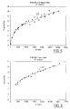
- Figure 5 is a desired graph plot 110 of flow rate through orifice 56 versus pressure drop across orifice 56 based on data from testing various modules 20. While some scatter in the data points is present, the scatter is less than in modules where tube 88 does not protrude into main flow passage 30. Hence, it is believed that extending the tube into the passage so that the open free end is spaced from the passage wall represents a meaningful improvement.
- Figures 2, 3, and 4 disclose a second embodiment of module that is like the first except in two respects.
- Like reference numerals designate like parts in both Figures 1 and 2, and so Figure 2 will be described only to the extent that it differs from Figure 1.
- a nozzle member 120 replaces orifice member 54, and the open free end 94 of tube 88 is substantially flush with the interior wall surface containing through-hole 96.
- Nozzle member 120 comprises a flow nozzle 122 that is profiled to contract the flow as the flow passes through it.
- Nozzle member 120 is fit concentric with port 34 via a rim 123 to constrain the flow to pass through flow nozzle 122, and flow nozzle 122 is coaxial with open free end 94 of tube 88.
- the entrance 124 of flow nozzle 122 is profiled to follow the shape of segment of an ellipse, a profile that is preferred, although a non-elliptically contoured profile may be suitable in some modules.
- the nozzle exit 126 is cylindrical.
- Figure 6 shows a desired graph plot 130 of flow rate through flow nozzle 122 versus pressure drop across flow nozzle 122 based on data from testing various Figure 2 modules. Very little scatter in the data points is present. Hence, it is believed that the use of a nozzle may provide even more precision in production modules.
- Figure 7 shows a desired graph plot 140 of flow rate through a valve like the one of Figure 1, except having a different sized orifice, versus pressure drop across the orifice.
- the plots 142, 144 represent 1% tolerance limits based on testing a number of valves at several different magnitudes of vacuum. It is believed that this shows that substantial accuracy in the flow characteristic can be obtained in production valves.
- the horizontal axis is presented as the product of MAP (manifold absolute pressure of the engine) and DP (pressure difference across the orifice or nozzle).
- module may be like Figure 2, but with the open free end 94 of tube 88 disposed in the manner of Figure 1.
Landscapes
- Engineering & Computer Science (AREA)
- Chemical & Material Sciences (AREA)
- Combustion & Propulsion (AREA)
- Mechanical Engineering (AREA)
- General Engineering & Computer Science (AREA)
- Physics & Mathematics (AREA)
- Fluid Mechanics (AREA)
- Analytical Chemistry (AREA)
- Electromagnetism (AREA)
- Measuring Volume Flow (AREA)
- Exhaust-Gas Circulating Devices (AREA)
- Indication Of The Valve Opening Or Closing Status (AREA)
- Measuring Fluid Pressure (AREA)
- Fluid-Driven Valves (AREA)
Abstract
Description
- This application expressly claims the benefit of earlier filing date and right of priority from the following patent application: U.S. Provisional Application Ser. No. 60/167,966, filed on 11/30/99 in the names of Frederic Gagnon, Peter Hueniken, and Kenneth Peter Nydam and entitled "EGR Flow Measurement Device And Method". The entirety of that earlier-filed, co-pending patent application is hereby expressly incorporated herein by reference.
- This invention relates generally to automotive emission control valves and systems, such as exhaust gas recirculation (EGR) valves that are used in exhaust emission control systems of automotive vehicle internal combustion engines. More specifically, the invention relates to an improvement for measuring the gas flow in an emission control valve and/or system.
- Commonly owned U.S. Patent No. 6,116,224 (Cook and Busato) discloses an EGR system comprising an EGR module. One element of that module is a pressure sensor that senses pressure differential across a circular orifice through which exhaust gas flow is constrained to pass when a valve of the module allows flow to the engine intake system.
- A circular orifice of given diameter possesses a known relationship between flow through the orifice and pressure drop across the orifice. In other words, flow through the orifice, and hence flow through the module, can be calculated by measurement of pressure drop across the orifice and applying the known flow/pressure drop relationship to the pressure drop measurement. U.S. Patent No. 6,116,224 shows various embodiments for communicating the pressure drop across the orifice to the pressure sensor.
- Actual measurements of flow through such modules at different pressure drops across their orifices have shown a certain amount of scatter relative to a relationship that should theoretically exist for an ideal orifice. It is believed that greater precision in flow control can be obtained if the amount of scatter can be reduced, and it is toward that objective that the present invention is directed.
- The invention arises out of several discoveries. A first discovery is that scatter can be reduced by how the sensing port of a pressure sensor is communicated to the gas flow passage that extends through a module. A second discovery is that scatter can be reduced by using a nozzle instead of an orifice. A third discovery results from combining the first two discoveries.
- One generic aspect of the invention relates to an internal combustion engine exhaust emission control system comprising a flow path for conveying exhaust gas from an exhaust system of the engine to an intake system of the engine. A valve selectively restricts the flow path. A pressure sensor having a pressure sensing port is communicated via a pressure sensing passage to the flow path. A side wall bounds a portion of the flow path, and the pressure sensing passage comprises a tube having an end portion passing through a through-hole in the side wall of the flow path to dispose an open free end of the tube within the flow path in spaced relation to the side wall.
- A further generic aspect relates an internal combustion engine exhaust emission control system comprising a flow path for conveying exhaust gas from an exhaust system of the engine to an intake system of the engine. A valve selectively restricts the flow path. A pressure sensor having a pressure sensing port is communicated via a pressure sensing passage to the flow path. A side wall bounds a portion of the flow path, and the pressure sensing passage comprises a tube having an end portion passing through a through-hole in the side wall of the flow path to communicate an open free end of the tube to the flow path in spaced relation to the side wall. A nozzle is disposed in the flow path opposite the open free end of the tube.
- The accompanying drawings, which are incorporated herein and constitute part of this specification, include one or more presently preferred embodiments of the invention, and together with a general description given above and a detailed description given below, serve to disclose principles of the invention in accordance with a best mode contemplated for carrying out the invention.
- Figure 1 is a front elevation view, partly in cross section, of a first embodiment of an exemplary module embodying principles of the present invention.
- Figure 2 is a partial front elevation view in cross section of a second embodiment of an exemplary module embodying principles of the present invention.
- Figure 3 is an enlarged view of one element of the second embodiment shown by itself.
- Figure 4 is full end view in the direction of
arrow 4 in Figure 3. - Figure 5 is a graph plot related to the first embodiment.
- Figure 6 is a graph plot related to the second embodiment.
- Figure 7 is a graph plot related to yet another embodiment.
- Figure 1 discloses a
module 20 embodying principles of the invention and comprising an emissioncontrol valve body 22, a fluid-pressure-operatedactuator 24, an electric-operatedpressure regulator valve 26, and asensor 28. Valve 26 is an electric-operated vacuum regulator valve, sometimes referred to as an EVR valve, andsensor 28 is a pressure sensor that provides an electric signal related to the magnitude of sensed vacuum. -
Valve body 22 comprises an internalmain flow passage 30 extending between afirst port 32 and asecond port 34. An annularvalve seat element 36 is disposed invalve body 22 to provide anannular seat surface 38 circumscribing a transverse cross-sectional area ofpassage 30. Avalve member 40 comprising a non-flow-throughvalve head 42 is disposed withinbody 22 coaxial with animaginary axis 44. Valvehead 42 is shown seated onseat surface 38closing passage 30 to flow betweenports - A stem 48 extends from
valve head 42 to operatively connecthead 42 withactuator 24 foroperating valve member 40 via the actuator. Stem 48 passes with a close sliding fit through a bushing 50 that is fit tobody 22 and guidesvalve member 40 for straight line motion alongaxis 44.Bushing 50 also captures the outer margin of a circular flange of a generally cylindricalwalled metal shield 52 on an internal shoulder ofvalve body 22.Shield 52 surrounds a portion of stem 48 to direct exhaust gas heat away from the stem when exhaust gas flows throughvalve body 22. Athin orifice member 54 comprising acircular orifice 56 is disposed atport 34 such that flow throughmain flow passage 30 is constrained to pass throughorifice 56. - Fluid-pressure-operated
actuator 24 comprises abody 58 that is in assembly withvalve body 22 coaxial withaxis 44.Actuator body 58 comprises afirst body part 60 and asecond body part 62.Body part 62 comprises sheet metal formed to a generally circular shape having a central through-hole 64 that allows the part to fit over a protruding end of bushing 50. Anannular gasket 66 is sandwiched betweenactuator body part 62 andvalve body 22.Actuator body part 62,gasket 66, andvalve body 22 each contains a like hole pattern that provides for the secure attachment ofpart 62 tovalve body 22 byheaded screws 70 whose threaded shanks are passed through aligned holes inpart 62 and gasket 66 and tightened into threaded holes inbody 22. -
Actuator body 58 comprises an interior that is divided into twochamber spaces metal part 78 and an outerflexible part 80.Part 80 has a circular annular shape including a convolution that rolls as wall 76 moves.Part 80 also has abead 82 which extends continuously around its outer margin and is held compressed betweenparts body part 62 being folded around and crimped against the outer margin ofpart 60, thereby securingparts chamber spaces part 80 is insert-molded onto the outer margin ofpart 78 to create a fluid-tight joint uniting the two parts. Several through-holes inpart 62 communicatechamber space 74 to atmosphere. A helicalcoil compression spring 84 is disposed withinchamber space 72 to resiliently bias movable wall 76 axially towardvalve seat surface 38, thereby urgingvalve head 42 toward seating onseat surface 38, and thereby closingpassage 30 to flow betweenports - EVR
valve 26 comprises a body having an atmospheric inlet port for communication to atmosphere, a source vacuum inlet port for communication to engine intake system vacuum, and a regulated vacuum outlet port. It contains an internal regulating mechanism like that of the EVR valves described in U.S. Patent No. 5,448,981, and 6,116,224. - The internal mechanism of
EVR valve 26 further comprises a solenoid that is operated by pulse width modulation. The pulse width modulation of the solenoid modulates the bleeding of vacuum to atmosphere to cause the vacuum in an internal chamber space to be regulated in accordance with the degree of signal modulation within a range that extends essentially from full intake system vacuum applied at the vacuum inlet port to essentially atmospheric pressure applied at the atmospheric inlet port. The regulated vacuum outlet port is directly in communication with that internal chamber space. An internal passage extends from that the regulated vacuum outlet port toactuator chamber space 72 to place the latter in fluid communication with the regulated vacuum inEVR valve 26. Because the regulated vacuum is established by modulation of the solenoid and is communicated tochamber space 72, the extent to which wall 76, and hencevalve member 40, is moved alongaxis 44 against the resistance ofspring 84 is controlled by the electric signal applied to the EVR solenoid. In this way, EGR flow to the engine intake system is closely controlled. - Intake system vacuum is communicated to a first pressure sensing port of
sensor 28 in any suitable way, for example such as through a tube schematically shown at 86. The tube communicates the intake system side oforifice 56 to the first pressure sensing port ofsensor 28. -
Sensor 28 comprises a second pressure sensing port that is communicated to pressure at the opposite side oforifice 56. The communication is established by a conduit comprising twotubes valve body 22 boundingmain flow path 30 comprises a right angle bend marked generally by thearrow 92. That bend is disposed betweenvalve seat surface 38 andorifice member 54. Hence,orifice 56 is disposed downstream of the bend. -
Tube 88 is a formed metal tube having an openfree end 94 that is opposite the end that is fitted totube 90. An end portion oftube 88 passes through a through-hole 96 in the wall ofvalve body 22 to dispose openfree end 94 withinmain flow path 30 in spaced relation to the valve body wall containing through-hole 96. Through-hole 96 is coaxial withorifice 56, and openfree end 94 faces and is also coaxial withorifice 56. Although stem 48 is disposed between openfree end 94 andorifice 56, pressure in the flow path upstream of the orifice can be accurately transmitted topressure sensor 28.Tube 88 includes anexternal shoulder 98 that abuts the exterior ofvalve body 22 surrounding through-hole 96 so that open free end is accurately positioned at a desired distance from the interior wall surface ofmain flow path 30 that contains the through-hole. - An
electric connector 100 provides forsensor 28 andEVR valve 26 to be connected with an electric control circuit (not shown).Connector 100 contains five electric terminals, three of which are associated withsensor 28 and two of which, withEVR valve 26. Whenconnector 100 is connected with a mating connector (not shown) leading to the electric circuit that operatesmodule 20, two electric terminals carry pulse width modulated current to the EVR solenoid, and three terminals carry electric current signals related to pressures sensed at the two sensing ports ofsensor 28. - Figure 5 is a desired
graph plot 110 of flow rate throughorifice 56 versus pressure drop acrossorifice 56 based on data from testingvarious modules 20. While some scatter in the data points is present, the scatter is less than in modules wheretube 88 does not protrude intomain flow passage 30. Hence, it is believed that extending the tube into the passage so that the open free end is spaced from the passage wall represents a meaningful improvement. - Figures 2, 3, and 4 disclose a second embodiment of module that is like the first except in two respects. Like reference numerals designate like parts in both Figures 1 and 2, and so Figure 2 will be described only to the extent that it differs from Figure 1.
- A
nozzle member 120 replacesorifice member 54, and the openfree end 94 oftube 88 is substantially flush with the interior wall surface containing through-hole 96. -
Nozzle member 120 comprises aflow nozzle 122 that is profiled to contract the flow as the flow passes through it.Nozzle member 120 is fit concentric withport 34 via arim 123 to constrain the flow to pass throughflow nozzle 122, and flownozzle 122 is coaxial with openfree end 94 oftube 88. Theentrance 124 offlow nozzle 122 is profiled to follow the shape of segment of an ellipse, a profile that is preferred, although a non-elliptically contoured profile may be suitable in some modules. Thenozzle exit 126 is cylindrical. - Figure 6 shows a desired
graph plot 130 of flow rate throughflow nozzle 122 versus pressure drop acrossflow nozzle 122 based on data from testing various Figure 2 modules. Very little scatter in the data points is present. Hence, it is believed that the use of a nozzle may provide even more precision in production modules. - Figure 7 shows a desired
graph plot 140 of flow rate through a valve like the one of Figure 1, except having a different sized orifice, versus pressure drop across the orifice. Theplots 142, 144 represent 1% tolerance limits based on testing a number of valves at several different magnitudes of vacuum. It is believed that this shows that substantial accuracy in the flow characteristic can be obtained in production valves. In all three Figures 5, 6, and 7, the horizontal axis is presented as the product of MAP (manifold absolute pressure of the engine) and DP (pressure difference across the orifice or nozzle). - Although not specifically shown in the drawings, another embodiment of module may be like Figure 2, but with the open
free end 94 oftube 88 disposed in the manner of Figure 1. - It is to be understood that because the invention may be practiced in various forms within the scope of the appended claims, certain specific words and phrases that may be used to describe a particular exemplary embodiment of the invention are not intended to necessarily limit the scope of the invention solely on account of such use.
Claims (14)
- An internal combustion engine exhaust emission control system comprising:a flow path for conveying exhaust gas from an exhaust system of the engine to an intake system of the engine and comprising a side wall bounding a portion of the flow path, a valve for selectively restricting the flow path, a pressure sensor having a pressure sensing port, and a pressure sensing passage communicating the pressure sensing port to the flow path,wherein the pressure sensing passage comprises a tube having an end portion passing through a through-hole in the side wall of the flow path to dispose an open free end of the tube within the flow path in spaced relation to the side wall.
- An internal combustion engine exhaust emission control system as set forth in Claim 1 including a device which is disposed downstream of the open free end of the tube, through which flow through the flow path is constrained to pass, and which creates a pressure drop in the flow path that bears a known relationship to flow rate through the device for correlating rate of flow through the device to pressure drop across the device.
- An internal combustion engine exhaust emission control system as set forth in Claim 2 in which the device comprises an orifice.
- An internal combustion engine exhaust emission control system as set forth in Claim 2 in which the device comprises a nozzle.
- An internal combustion engine exhaust emission control system as set forth in Claim 4 in which the nozzle constricts the flow passing through it.
- An internal combustion engine exhaust emission control system as set forth in Claim 1 in which the side wall bounding a portion of the flow path comprises a valve body having a through-passage extending between an inlet port and a valve seat disposed between the inlet port and the outlet port circumscribing the through-passage, the through-passage comprises a bend between the valve seat and the outlet port, the device is disposed downstream of the bend and the open free end of the tube faces the device.
- An internal combustion engine exhaust emission control system as set forth in Claim 6 in which the open free end of the tube is coaxial with the device.
- An internal combustion engine exhaust emission control system as set forth in Claim 7 in which the valve comprises a head that coacts with the valve seat to selectively restrict flow through the flow path, and a stem that extends from the valve head to an actuator for positioning the valve head relative to the valve seat and that is disposed between the open free end of the tube and the device.
- An internal combustion engine exhaust emission control system comprising:a flow path for conveying exhaust gas from an exhaust system of the engine to an intake system of the engine and comprising a side wall bounding a portion of the flow path, a valve for selectively restricting the flow path, a pressure sensor having a pressure sensing port, and a pressure sensing passage communicating the pressure sensing port to the flow path, a device which is disposed downstream of where the pressure sensing passage communicates to the flow path, through which flow through the flow path is constrained to pass, and which creates a pressure drop in the flow path that bears a known relationship to flow rate through the device for correlating rate of flow through the device to pressure drop across the device.wherein the device comprises a nozzle.
- An internal combustion engine exhaust emission control system as set forth in Claim 9 in which the pressure sensing passage comprises a tube having an end portion passing through a through-hole in the side wall of the flow path to dispose an open free end of the tube substantially flush with the side wall.
- An internal combustion engine exhaust emission control system as set forth in Claim 9 in which the nozzle constricts the flow passing through it.
- An internal combustion engine exhaust emission control system as set forth in Claim 11 in which the side wall bounding a portion of the flow path comprises a valve body having a through-passage extending between an inlet port and a valve seat disposed between the inlet port and the outlet port circumscribing the through-passage, the through-passage comprises a bend between the valve seat and the outlet port, the device is disposed downstream of the bend and the open free end of the tube faces the device.
- An internal combustion engine exhaust emission control system as set forth in Claim 12 in which the open free end of the tube is coaxial with the device.
- An internal combustion engine exhaust emission control system as set forth in Claim 13 in which the valve comprises a head that coacts with the valve seat to selectively restrict flow through the flow path, and a stem that extends from the valve head to an actuator for positioning the valve head relative to the valve seat and that is disposed between the open free end of the tube and the device.
Applications Claiming Priority (5)
| Application Number | Priority Date | Filing Date | Title |
|---|---|---|---|
| US16796699P | 1999-11-30 | 1999-11-30 | |
| US167966P | 1999-11-30 | ||
| US09/722,763 US6431158B1 (en) | 1999-11-30 | 2000-11-27 | Exhaust gas flow measurment device |
| US722763 | 2000-11-27 | ||
| 2001-02-02 |
Publications (3)
| Publication Number | Publication Date |
|---|---|
| EP1106812A2 true EP1106812A2 (en) | 2001-06-13 |
| EP1106812A3 EP1106812A3 (en) | 2002-01-02 |
| EP1106812B1 EP1106812B1 (en) | 2003-09-17 |
Family
ID=26863672
Family Applications (1)
| Application Number | Title | Priority Date | Filing Date |
|---|---|---|---|
| EP00204249A Expired - Lifetime EP1106812B1 (en) | 1999-11-30 | 2000-11-29 | Exhaust gas flow measurement device |
Country Status (3)
| Country | Link |
|---|---|
| US (1) | US6431158B1 (en) |
| EP (1) | EP1106812B1 (en) |
| DE (1) | DE60005278T2 (en) |
Families Citing this family (1)
| Publication number | Priority date | Publication date | Assignee | Title |
|---|---|---|---|---|
| US7478631B2 (en) * | 2006-05-05 | 2009-01-20 | Siemens Canada Limited | PZEV exhaust gas recirculation valve with activated carbon |
Citations (2)
| Publication number | Priority date | Publication date | Assignee | Title |
|---|---|---|---|---|
| US5448981A (en) | 1990-03-08 | 1995-09-12 | Siemens Automotive Limited | Regulated flow canister purge system |
| US6116224A (en) | 1998-05-26 | 2000-09-12 | Siemens Canada Ltd. | Automotive vehicle having a novel exhaust gas recirculation module |
Family Cites Families (12)
| Publication number | Priority date | Publication date | Assignee | Title |
|---|---|---|---|---|
| US4186699A (en) | 1973-03-27 | 1980-02-05 | Nissan Motor Company, Limited | Exhaust gas recirculation system |
| US4022237A (en) | 1974-02-28 | 1977-05-10 | The Bendix Corporation | Exhaust gas recirculation flow control system |
| US3981283A (en) | 1974-09-03 | 1976-09-21 | Ford Motor Company | Engine exhaust gas recirculating control |
| US4196707A (en) * | 1978-07-31 | 1980-04-08 | General Motors Corporation | Exhaust gas recirculation control |
| US4566423A (en) | 1983-12-20 | 1986-01-28 | Eaton Corporation | Electronic feedback EGR valve |
| US4690120A (en) * | 1986-02-25 | 1987-09-01 | Eaton Corporation | Exhaust gas recirculation control system |
| JP2564718B2 (en) * | 1991-09-18 | 1996-12-18 | 三菱電機株式会社 | Exhaust gas recirculation control device failure diagnosis device |
| JPH05288123A (en) * | 1992-04-10 | 1993-11-02 | Toyota Motor Corp | Exhaust gas circulation apparatus for internal combustion engine |
| JPH08226354A (en) * | 1995-02-20 | 1996-09-03 | Unisia Jecs Corp | Diagnostic device for exhaust gas recirculation system of internal combustion engine |
| US5613479A (en) | 1995-12-08 | 1997-03-25 | Ford Motor Company | Pressure feedback exhaust gas recirculation system |
| US6014961A (en) * | 1998-07-23 | 2000-01-18 | Ford Global Technologies, Inc. | Internal combustion engine intake sensing system |
| EP1204819B1 (en) | 1999-08-17 | 2007-02-21 | Siemens VDO Automotive Inc. | Exhaust gas recirculation system module |
-
2000
- 2000-11-27 US US09/722,763 patent/US6431158B1/en not_active Expired - Fee Related
- 2000-11-29 EP EP00204249A patent/EP1106812B1/en not_active Expired - Lifetime
- 2000-11-29 DE DE60005278T patent/DE60005278T2/en not_active Expired - Lifetime
Patent Citations (2)
| Publication number | Priority date | Publication date | Assignee | Title |
|---|---|---|---|---|
| US5448981A (en) | 1990-03-08 | 1995-09-12 | Siemens Automotive Limited | Regulated flow canister purge system |
| US6116224A (en) | 1998-05-26 | 2000-09-12 | Siemens Canada Ltd. | Automotive vehicle having a novel exhaust gas recirculation module |
Also Published As
| Publication number | Publication date |
|---|---|
| EP1106812B1 (en) | 2003-09-17 |
| US6431158B1 (en) | 2002-08-13 |
| EP1106812A3 (en) | 2002-01-02 |
| DE60005278D1 (en) | 2003-10-23 |
| DE60005278T2 (en) | 2004-07-08 |
Similar Documents
| Publication | Publication Date | Title |
|---|---|---|
| US7950377B2 (en) | EGR system and EGR valve with integrated pressure sensor | |
| US7814893B2 (en) | Exhaust gas recirculation system module with integral vacuum | |
| US6050245A (en) | Canister vent valve having at least one sensor and single electric actuator operatively connected to a single electrical connector | |
| US5369990A (en) | Remote mount air flow sensor | |
| US6189520B1 (en) | Integration of sensor, actuator, and regulator valve in an emission control module | |
| US5988149A (en) | Pressure sensing system for an internal combustion engine | |
| US6116224A (en) | Automotive vehicle having a novel exhaust gas recirculation module | |
| US6230694B1 (en) | Calibration and testing of an automotive emission control module | |
| US5609143A (en) | Exhaust gas recirculation valve for an internal combustion engine | |
| US5188086A (en) | Exhaust gas recirculation coupler and differential venturi | |
| US6415777B1 (en) | EGR module having orifice in a pressure sensing port | |
| US6431158B1 (en) | Exhaust gas flow measurment device | |
| US6330878B1 (en) | Evaporative emission leak detection system including vacuum regulator with sensitive seal | |
| US4531498A (en) | Exhaust gas recirculation control and subassemblies therefor | |
| US6170476B1 (en) | Internal sensing passage in an exhaust gas recirculation module | |
| EP1312787B1 (en) | Fluid control valve system | |
| US6502564B1 (en) | Exhaust gas recirculation system module | |
| US6138652A (en) | Method of making an automotive emission control module having fluid-power-operated actuator, fluid pressure regulator valve, and sensor | |
| EP1222381B1 (en) | Exhaust gas recirculation valve having an angled seat | |
| US4196744A (en) | Exhaust gas recirculation control | |
| US4114575A (en) | Exhaust pressure regulating system | |
| US6460523B1 (en) | EGR system for an internal combustion engine | |
| US6997170B2 (en) | Exhaust gas recirculation (EGR) module having sensor integrated into cover (ESM) | |
| US20070256674A1 (en) | PZEV exhaust gas recirculation valve with activated carbon |
Legal Events
| Date | Code | Title | Description |
|---|---|---|---|
| PUAI | Public reference made under article 153(3) epc to a published international application that has entered the european phase |
Free format text: ORIGINAL CODE: 0009012 |
|
| AK | Designated contracting states |
Kind code of ref document: A2 Designated state(s): DE FR GB IT SE Kind code of ref document: A2 Designated state(s): AT BE CH CY DE DK ES FI FR GB GR IE IT LI LU MC NL PT SE TR |
|
| AX | Request for extension of the european patent |
Free format text: AL;LT;LV;MK;RO;SI |
|
| PUAL | Search report despatched |
Free format text: ORIGINAL CODE: 0009013 |
|
| AK | Designated contracting states |
Kind code of ref document: A3 Designated state(s): AT BE CH CY DE DK ES FI FR GB GR IE IT LI LU MC NL PT SE TR |
|
| AX | Request for extension of the european patent |
Free format text: AL;LT;LV;MK;RO;SI |
|
| 17P | Request for examination filed |
Effective date: 20020409 |
|
| 17Q | First examination report despatched |
Effective date: 20020604 |
|
| AKX | Designation fees paid |
Free format text: DE FR GB IT SE |
|
| GRAH | Despatch of communication of intention to grant a patent |
Free format text: ORIGINAL CODE: EPIDOS IGRA |
|
| RAP1 | Party data changed (applicant data changed or rights of an application transferred) |
Owner name: SIEMENS VDO AUTOMOTIVE INC. |
|
| GRAS | Grant fee paid |
Free format text: ORIGINAL CODE: EPIDOSNIGR3 |
|
| GRAA | (expected) grant |
Free format text: ORIGINAL CODE: 0009210 |
|
| AK | Designated contracting states |
Kind code of ref document: B1 Designated state(s): DE FR GB IT SE |
|
| REG | Reference to a national code |
Ref country code: GB Ref legal event code: FG4D |
|
| REF | Corresponds to: |
Ref document number: 60005278 Country of ref document: DE Date of ref document: 20031023 Kind code of ref document: P |
|
| REG | Reference to a national code |
Ref country code: IE Ref legal event code: FG4D |
|
| REG | Reference to a national code |
Ref country code: SE Ref legal event code: TRGR |
|
| ET | Fr: translation filed | ||
| PLBE | No opposition filed within time limit |
Free format text: ORIGINAL CODE: 0009261 |
|
| STAA | Information on the status of an ep patent application or granted ep patent |
Free format text: STATUS: NO OPPOSITION FILED WITHIN TIME LIMIT |
|
| 26N | No opposition filed |
Effective date: 20040618 |
|
| REG | Reference to a national code |
Ref country code: IE Ref legal event code: MM4A |
|
| PGFP | Annual fee paid to national office [announced via postgrant information from national office to epo] |
Ref country code: SE Payment date: 20041109 Year of fee payment: 5 |
|
| PGFP | Annual fee paid to national office [announced via postgrant information from national office to epo] |
Ref country code: FR Payment date: 20041117 Year of fee payment: 5 |
|
| PG25 | Lapsed in a contracting state [announced via postgrant information from national office to epo] |
Ref country code: IT Free format text: LAPSE BECAUSE OF NON-PAYMENT OF DUE FEES Effective date: 20051129 |
|
| PG25 | Lapsed in a contracting state [announced via postgrant information from national office to epo] |
Ref country code: SE Free format text: LAPSE BECAUSE OF NON-PAYMENT OF DUE FEES Effective date: 20051130 |
|
| EUG | Se: european patent has lapsed | ||
| PG25 | Lapsed in a contracting state [announced via postgrant information from national office to epo] |
Ref country code: FR Free format text: LAPSE BECAUSE OF NON-PAYMENT OF DUE FEES Effective date: 20060731 |
|
| REG | Reference to a national code |
Ref country code: FR Ref legal event code: ST Effective date: 20060731 |
|
| PGFP | Annual fee paid to national office [announced via postgrant information from national office to epo] |
Ref country code: DE Payment date: 20121130 Year of fee payment: 13 |
|
| PGFP | Annual fee paid to national office [announced via postgrant information from national office to epo] |
Ref country code: GB Payment date: 20121120 Year of fee payment: 13 |
|
| GBPC | Gb: european patent ceased through non-payment of renewal fee |
Effective date: 20131129 |
|
| REG | Reference to a national code |
Ref country code: DE Ref legal event code: R119 Ref document number: 60005278 Country of ref document: DE Effective date: 20140603 |
|
| PG25 | Lapsed in a contracting state [announced via postgrant information from national office to epo] |
Ref country code: DE Free format text: LAPSE BECAUSE OF NON-PAYMENT OF DUE FEES Effective date: 20140603 |
|
| PG25 | Lapsed in a contracting state [announced via postgrant information from national office to epo] |
Ref country code: GB Free format text: LAPSE BECAUSE OF NON-PAYMENT OF DUE FEES Effective date: 20131129 |