EP1106778A1 - Seal for expandable tubular connections - Google Patents
Seal for expandable tubular connections Download PDFInfo
- Publication number
- EP1106778A1 EP1106778A1 EP00127090A EP00127090A EP1106778A1 EP 1106778 A1 EP1106778 A1 EP 1106778A1 EP 00127090 A EP00127090 A EP 00127090A EP 00127090 A EP00127090 A EP 00127090A EP 1106778 A1 EP1106778 A1 EP 1106778A1
- Authority
- EP
- European Patent Office
- Prior art keywords
- clearance
- connection
- seal
- sealing
- proximal
- Prior art date
- Legal status (The legal status is an assumption and is not a legal conclusion. Google has not performed a legal analysis and makes no representation as to the accuracy of the status listed.)
- Granted
Links
- 238000007789 sealing Methods 0.000 claims abstract description 59
- 230000008878 coupling Effects 0.000 abstract description 17
- 238000010168 coupling process Methods 0.000 abstract description 17
- 238000005859 coupling reaction Methods 0.000 abstract description 17
- 239000002184 metal Substances 0.000 description 5
- 230000000295 complement effect Effects 0.000 description 3
- 239000012530 fluid Substances 0.000 description 3
- 230000013011 mating Effects 0.000 description 3
- 230000001419 dependent effect Effects 0.000 description 1
- 238000005553 drilling Methods 0.000 description 1
- 238000011065 in-situ storage Methods 0.000 description 1
- 238000004519 manufacturing process Methods 0.000 description 1
- 239000000463 material Substances 0.000 description 1
- 230000036316 preload Effects 0.000 description 1
Images

Classifications
-
- E—FIXED CONSTRUCTIONS
- E21—EARTH OR ROCK DRILLING; MINING
- E21B—EARTH OR ROCK DRILLING; OBTAINING OIL, GAS, WATER, SOLUBLE OR MELTABLE MATERIALS OR A SLURRY OF MINERALS FROM WELLS
- E21B43/00—Methods or apparatus for obtaining oil, gas, water, soluble or meltable materials or a slurry of minerals from wells
- E21B43/02—Subsoil filtering
- E21B43/10—Setting of casings, screens, liners or the like in wells
- E21B43/103—Setting of casings, screens, liners or the like in wells of expandable casings, screens, liners, or the like
- E21B43/106—Couplings or joints therefor
-
- E—FIXED CONSTRUCTIONS
- E21—EARTH OR ROCK DRILLING; MINING
- E21B—EARTH OR ROCK DRILLING; OBTAINING OIL, GAS, WATER, SOLUBLE OR MELTABLE MATERIALS OR A SLURRY OF MINERALS FROM WELLS
- E21B17/00—Drilling rods or pipes; Flexible drill strings; Kellies; Drill collars; Sucker rods; Cables; Casings; Tubings
- E21B17/02—Couplings; joints
- E21B17/04—Couplings; joints between rod or the like and bit or between rod and rod or the like
- E21B17/042—Threaded
- E21B17/043—Threaded with locking means
-
- E—FIXED CONSTRUCTIONS
- E21—EARTH OR ROCK DRILLING; MINING
- E21B—EARTH OR ROCK DRILLING; OBTAINING OIL, GAS, WATER, SOLUBLE OR MELTABLE MATERIALS OR A SLURRY OF MINERALS FROM WELLS
- E21B43/00—Methods or apparatus for obtaining oil, gas, water, soluble or meltable materials or a slurry of minerals from wells
- E21B43/02—Subsoil filtering
- E21B43/10—Setting of casings, screens, liners or the like in wells
- E21B43/103—Setting of casings, screens, liners or the like in wells of expandable casings, screens, liners, or the like
-
- F—MECHANICAL ENGINEERING; LIGHTING; HEATING; WEAPONS; BLASTING
- F16—ENGINEERING ELEMENTS AND UNITS; GENERAL MEASURES FOR PRODUCING AND MAINTAINING EFFECTIVE FUNCTIONING OF MACHINES OR INSTALLATIONS; THERMAL INSULATION IN GENERAL
- F16L—PIPES; JOINTS OR FITTINGS FOR PIPES; SUPPORTS FOR PIPES, CABLES OR PROTECTIVE TUBING; MEANS FOR THERMAL INSULATION IN GENERAL
- F16L15/00—Screw-threaded joints; Forms of screw-threads for such joints
- F16L15/001—Screw-threaded joints; Forms of screw-threads for such joints with conical threads
- F16L15/004—Screw-threaded joints; Forms of screw-threads for such joints with conical threads with axial sealings having at least one plastically deformable sealing surface
Definitions
- the invention is related to threaded tubular joins usable in oil and gas well drilling and production, such as tubing, casing, line pipe, and drill pipe, commonly known collectively as oilfield tubular goods. More particularly, the invention relates to a seal for tubular joints for connecting male (pin) and female (box) members and preferably. to the collapsing type seal.
- Threaded tubular connections are used for joining segments of conduits end-to-end to form a continuous conduit for transporting fluid under pressure.
- Oilfield tubular goods generally use such threaded connections for connecting adjacent sections of conduit or pipe. Examples of such threaded end connections designed for use on oilfield tubular goods are disclosed in U.S. Patent Nos. 2,239,942; 2,992,019; 3,359,013; RE 30,647; and RE 34,467, all of which are assigned to the assignee of this invention.
- the angles of the flank shoulder, as well as the thread width can be used to control the stress and strain preload conditions induced in the pin and box members for a given make-up torque.
- the tubular connection or joint is limited only by the properties of the materials selected.
- a prior art tubular connection 10 includes a pin member 11 and a box member 12.
- Box member 12 has a tapered, internal, generally dovetail-shaped thread structure 14 formed thereon which is adapted for engaging complementary tapered, external, generally dovetail-shaped thread structure 15 formed on pin member 11 to mechanically secure the box 12 and pin 11 members in a releasable manner.
- Internal thread 14 on the box member 12 has stab flanks 18, load flanks 16, roots 20, and crests 24.
- the thread 14 increases in width progressively at a uniform rate in one direction over substantially the entire helical length of thread 14.
- External thread 15 of pin member 11 has stab flank, 19, load flanks 17, roots 21, and crests 25.
- the thread 15 increases in width progressively at a uniform rate in the other direction over substantially the entire helical length of thread 15.
- the oppositely increasing thread widths and the taper of threads 14 and 15 cause the complementary roots and crests of the respective threads 14 and 15 to move iinto engagement, during make-up of the connection 10 in conjunction with the moving of complementary stab and load flanks into engagement upon make-up of the connection.
- the pin member 11 of the box member 12 defines the longitudinal axis 13 of the made-up connection 10.
- the roots and crests of the box and pin members are flat and parallel to the longitudinal axis of the connection and have sufficient width to prevent any permanent deformation of the threads when the connection is made up.
- connection An important part of any connection is a seal for keeping the conduit fluid pressure-tight at the connections.
- connections will be designed to include metal-to-metal seals therein.
- Metal-to-metal seals have the advantage of not requiring gaskets or other additional sealing devices, which would typically have to be replaced periodically as the connections are coupled and uncoupled.
- Metal seals are created when contact pressure between two metal surfaces exceeds the fluid pressure to be sealed. Typically the contact pressures are created during make up of the connection.
- Oilfield tubular goods have been developed which can be radially expanded from their initial diameters after being installed for the intended application. See for example, R. D. Mack et al, How in situ expansion affects casing and tubing properties, World Oil, July 1999, Gulf Publishing Co., Houston, TX, for a description of radially expanding Oilfield tubular goods.
- Radially expandable tubular goods have particular application as casing in oil and gas producing wells. It has been difficult to seal radially expandable tubular connections using metal-to-metal seals known in the art. It is one object of the present invention to obtain such a seal.
- the present invention provides a seal for a radially expansible connection according to independent claim. Further advantageous features, aspect and details of the invention are evident from the dependent claims, the description and the drawings. The claims are intended to be understood as a first non-limiting approach of defining the invention in general terms.
- the invention according to a specific aspect provides a seal for a radially expansible conduit connection or coupling.
- the seal preferably includes a first sealing surface disposed proximal to an end of a male portion of the connection, and a corresponding second sealing surface disposed proximal to an end of a female portion of the connection. It is preferred that the first and said second sealing surfaces are substantially opposite each other upon connection of the male and female portions.
- the seal may include a first clearance surface proximal to the first sealing surface on the male portion and a second clearance surface proximal to the second sealing surface on the female portion. The first and second clearance surfaces are preferably substantially opposite each other upon connection of the male and female portions.
- the first and second clearance surfaces, and the first and second sealing surfaces advantageously each have a diameter such that prior to radial expansion, the clearance surfaces do not contact each other.
- the clearance surfaces Upon radial expansion of the male portion and female portion after coupling together thereof, the clearance surfaces preferably remain out of contact and the sealing surfaces preferably contact each other so as to develop a contact pressure.
- the clearance between the sealing surfaces prior to radial expansion of the connection is about 30 to 40 percent of the amount of radial expansion.
- the clearance between the clearance surfaces prior to radial expansion is about 50 to 55 percent of the amount of radial expansion.
- the sealing surfaces are in interference fit prior to radial expansion of the connection. After the radial expansion, the contact pressure between the sealing surfaces is increased.
- the coupling is a threaded coupling including mating threads on the male and female portions of the coupling.
- the clearance surface on the male portion preferably is proximal to the thread end, and the clearance surface on the female portion is preferably proximal to the thread start in the threaded coupling embodiment.
- Figure 1 shows a prior art tubular threaded connection.
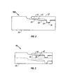
- Figure 2 shows a partial view of one embodiment of the connection seal of the invention prior to radial expansion of the tubular joints and connection.
- Figure 3 shows a partial view of one embodiment of the connection seal of the invention after radial expansion of the tubular joints and connection
- Figure 2 relates to one example of a tubular connection 10A as used on radially expandable tubular goods.
- the example shown in Figure 2 is for a threaded coupling.
- Figure 2 is a cross-section through only one side of the threaded tubular connection 10A, and the view shown in Figure 2 should therefore be thought of as rotationally symmetric about the axis (not shown) of the tubular connection 10A.
- the tubular connection 10A is formed by joining a male-threaded "pin” member 30 to a female-threaded "box” member 32.
- the pin 30 and box 32 members have thereon corresponding threads 36 and 34, respectively, which when engaged provide axial coupling force to join tubular joints together.
- the threads 34, 36 can be any type known in the art for coupling together tubular goods, and may be a sealing type or a non-sealing type.
- the particular type of threads selected will depend, as is known in the art, on the intended use of the tubular goods being joined by the connection 10A.
- the type of threads is not intended to limit the invention.
- the connection 10A can be formed wherein segments of conduit (not shown separately) include a pin at both ends and arc connected by a short segment having box members at both ends, the short segment being known as a "collar".
- the connection 10A can also be formed wherein each segment of conduit includes therein a pin at one end and a box at the other. Either conduit connection will work with this invention.
- the box member 32 includes at its thread start end a clearance surface 42 and a scaling surface 44.
- the pin member 30 includes thereon at the end of the threads 36 a corresponding clearance surface 38 and sealing surface 40.
- the sealing surfaces 40 and 44 may be parallel, but the sealing surfaces 40, 44 are preferably tapered as shown in Figure 2.
- the sealing surfaces 40, 44 as shown in Figure 2 are parallel to each other as well as being tapered, it should be understood that the sealing surfaces 40, 44 need not be parallel to each other.
- the clearance between the clearance surfaces 38, 42 is greater than the clearance between the sealing surfaces 40, 44 prior to radial expansion of the pin member 30 and box member 32.
- the additional clearance between the clearance surfaces 38, 42 results in a radially-inward deformation of the seal surface area (particularly seal surface 44) on the box 32 when the box 32 is radially expanded, which results in a high contact pressure between the sealing surfaces 40, 44.
- the clearance surface 42 on the box 32 has a larger internal diameter than does the seal surface 40 on the box 32 to provide the larger clearance between corresponding clearance surfaces 38, 42 than the corresponding seal surfaces 40, 44.
- Figure 2 shows the sealing surfaces 40, 44 as having a small amount of clearance between them prior to radial expansion of the pin 30 and box 32
- the sealing surfaces 40, 44 may also be in interference contact with each other. Where the sealing surfaces 40, 44 are in interference contact prior to radial expansion, after radial expansion the sealing surfaces 40, 44 will contact each other at a higher contact pressure than prior to expansion as long as the clearance surfaces 38, 42 remain out of contact after expansion.
- the amount of clearance between the clearance surfaces 38, 42 prior to radial expansion will depend on, among other factors, the amount of radial expansion to be applied to the pin 30 and box 32, and the pre-expansion diameter of the pin 30 and box 32. Generally, large clearance where the amount of expansion is small, or small clearance where the amount of clearance is to be large are not highly desirable.
- a preferred amount of clearance between the sealing surfaces is about 30 to 40 percent of the amount of expansion to be applied, although other clearances will work with the invention, including interference fit, as previously explained.
- a preferred pre-expansion clearance for the clearance surfaces is about 50 to 55 percent of the amount of radial expansion, although other clearances will work with the invention. The important aspect is that the clearance surfaces 38, 42 retain some clearance therebetween after radial expansion of the box 32 and pin 30.
- Figure 3 shows the connection 10A after radial expansion of the pin 30 and box 32.
- the scaling surfaces 40, 44 have been put into sealing contact with each other by reason of the radial expansion of the pin 30 and box 32.
- the clearance surfaces 38, 42 do not come into contact with each other as a result of the radial expansion of the pin 30 and box 32.
- a seal for a radially expansible conduit connection includes a first sealing surface (40) disposed proximal to an end of a male portion (30) of the connection and a corresponding second sealing surface (44) diposed proximal to to an end of a female portion (32) of the connection.
- the first and said second sealing surfaces (40,44) are substantially opposite each other upon connection of the male (30) and female (32) portions.
- the seal includes a first clearance surface (38) proximal to the first sealing surface (40) and a second clearance surface (42) proximal to the second sealing surface (44).
- the first and second clearance surfaces (38.42) are substantially opposite each other upon connection of the male (30) and female (32) portions.
- the first and second clearance surfaces (38,42), and the first and second sealing surfaces (40,44) each have a diameter such that upon radial expansion of the male portion (30) and the female portion (32) after coupling together thereof, the clearance surfaces (38,42). remain out of contact while the sealing surfaces (40,44) contact each other so as to develop a contact pressure.
- the clearance between the sealing surfaces (40,44) prior to expansion is about 30-40 percent of the amount of expansion.
- the sealing surfaces (40,44) are in interference contact prior to expansion.
- the clearance surfaces (38,42) have a clearance prior expansion, of about 50 to 55 percent of the amount of expansion.
- the conduit connection is a threaded coupling (34,36).
Landscapes
- Engineering & Computer Science (AREA)
- Geology (AREA)
- Life Sciences & Earth Sciences (AREA)
- Mining & Mineral Resources (AREA)
- Environmental & Geological Engineering (AREA)
- Fluid Mechanics (AREA)
- Physics & Mathematics (AREA)
- General Life Sciences & Earth Sciences (AREA)
- Geochemistry & Mineralogy (AREA)
- Mechanical Engineering (AREA)
- General Engineering & Computer Science (AREA)
- Earth Drilling (AREA)
- Non-Disconnectible Joints And Screw-Threaded Joints (AREA)
- Gasket Seals (AREA)
Abstract
Description
- The invention is related to threaded tubular joins usable in oil and gas well drilling and production, such as tubing, casing, line pipe, and drill pipe, commonly known collectively as oilfield tubular goods. More particularly, the invention relates to a seal for tubular joints for connecting male (pin) and female (box) members and preferably. to the collapsing type seal.
- Threaded tubular connections are used for joining segments of conduits end-to-end to form a continuous conduit for transporting fluid under pressure. Oilfield tubular goods generally use such threaded connections for connecting adjacent sections of conduit or pipe. Examples of such threaded end connections designed for use on oilfield tubular goods are disclosed in U.S. Patent Nos. 2,239,942; 2,992,019; 3,359,013; RE 30,647; and RE 34,467, all of which are assigned to the assignee of this invention.
- In U.S. Patent No. RE 30,647 issued to Blose, a particular thread form or structure is disclosed for a tubular connection that provides a strong joint while controlling the stress and strain in connected "pin" (male thread) and "box" (female thread) members to within acceptable levels. The pin member has at least one generally dovetail-shaped external thread whose width increases in one direction along the pin, while the box member has at least one matching generally dovetail-shaped internal thread whose width increases in the other direction. The mating set of helical threads provide a wedge-like engagement of opposing pin and box thread flanks that limit the extent of relative rotation between the pin and box members, and define a forcible make-up condition that completes the connection. In this thread structure, the angles of the flank shoulder, as well as the thread width, can be used to control the stress and strain preload conditions induced in the pin and box members for a given make-up torque. Thus, by tailoring the thread structure to a particular application or use, the tubular connection or joint is limited only by the properties of the materials selected.
- As shown in Figure 1, a prior art
tubular connection 10 includes apin member 11 and abox member 12.Box member 12 has a tapered, internal, generally dovetail-shaped thread structure 14 formed thereon which is adapted for engaging complementary tapered, external, generally dovetail-shaped thread structure 15 formed onpin member 11 to mechanically secure thebox 12 andpin 11 members in a releasable manner. -
Internal thread 14 on thebox member 12 hasstab flanks 18,load flanks 16,roots 20, andcrests 24. Thethread 14 increases in width progressively at a uniform rate in one direction over substantially the entire helical length ofthread 14. External thread 15 ofpin member 11 has stab flank, 19,load flanks 17,roots 21, and crests 25. The thread 15 increases in width progressively at a uniform rate in the other direction over substantially the entire helical length of thread 15. The oppositely increasing thread widths and the taper ofthreads 14 and 15, cause the complementary roots and crests of therespective threads 14 and 15 to move iinto engagement, during make-up of theconnection 10 in conjunction with the moving of complementary stab and load flanks into engagement upon make-up of the connection. - The
pin member 11 of thebox member 12 defines thelongitudinal axis 13 of the made-upconnection 10. The roots and crests of the box and pin members are flat and parallel to the longitudinal axis of the connection and have sufficient width to prevent any permanent deformation of the threads when the connection is made up. - An important part of any connection is a seal for keeping the conduit fluid pressure-tight at the connections. Typically connections will be designed to include metal-to-metal seals therein. Metal-to-metal seals have the advantage of not requiring gaskets or other additional sealing devices, which would typically have to be replaced periodically as the connections are coupled and uncoupled. Metal seals are created when contact pressure between two metal surfaces exceeds the fluid pressure to be sealed. Typically the contact pressures are created during make up of the connection.
- More recently, oilfield tubular goods have been developed which can be radially expanded from their initial diameters after being installed for the intended application. See for example, R. D. Mack et al, How in situ expansion affects casing and tubing properties, World Oil, July 1999, Gulf Publishing Co., Houston, TX, for a description of radially expanding Oilfield tubular goods. Radially expandable tubular goods have particular application as casing in oil and gas producing wells. It has been difficult to seal radially expandable tubular connections using metal-to-metal seals known in the art. It is one object of the present invention to obtain such a seal.
- The present invention provides a seal for a radially expansible connection according to independent claim. Further advantageous features, aspect and details of the invention are evident from the dependent claims, the description and the drawings. The claims are intended to be understood as a first non-limiting approach of defining the invention in general terms.
- The invention according to a specific aspect provides a seal for a radially expansible conduit connection or coupling. The seal preferably includes a first sealing surface disposed proximal to an end of a male portion of the connection, and a corresponding second sealing surface disposed proximal to an end of a female portion of the connection. It is preferred that the first and said second sealing surfaces are substantially opposite each other upon connection of the male and female portions. The seal may include a first clearance surface proximal to the first sealing surface on the male portion and a second clearance surface proximal to the second sealing surface on the female portion. The first and second clearance surfaces are preferably substantially opposite each other upon connection of the male and female portions. The first and second clearance surfaces, and the first and second sealing surfaces advantageously each have a diameter such that prior to radial expansion, the clearance surfaces do not contact each other. Upon radial expansion of the male portion and female portion after coupling together thereof, the clearance surfaces preferably remain out of contact and the sealing surfaces preferably contact each other so as to develop a contact pressure.
- In one specific aspect, the clearance between the sealing surfaces prior to radial expansion of the connection is about 30 to 40 percent of the amount of radial expansion.
- In a further aspect, the clearance between the clearance surfaces prior to radial expansion is about 50 to 55 percent of the amount of radial expansion.
- In still another aspect, the sealing surfaces are in interference fit prior to radial expansion of the connection. After the radial expansion, the contact pressure between the sealing surfaces is increased.
- In one advantageous aspect embodiment, the coupling is a threaded coupling including mating threads on the male and female portions of the coupling. The clearance surface on the male portion preferably is proximal to the thread end, and the clearance surface on the female portion is preferably proximal to the thread start in the threaded coupling embodiment.
- Figure 1 showsa prior art tubular threaded connection.
- Figure 2 shows a partial view of one embodiment of the connection seal of the invention prior to radial expansion of the tubular joints and connection.
- Figure 3 shows a partial view of one embodiment of the connection seal of the invention after radial expansion of the tubular joints and connection,
- Figure 2 relates to one example of a
tubular connection 10A as used on radially expandable tubular goods. The example shown in Figure 2 is for a threaded coupling. Figure 2 is a cross-section through only one side of the threadedtubular connection 10A, and the view shown in Figure 2 should therefore be thought of as rotationally symmetric about the axis (not shown) of thetubular connection 10A. Thetubular connection 10A is formed by joining a male-threaded "pin"member 30 to a female-threaded "box"member 32. Thepin 30 andbox 32 members have thereoncorresponding threads threads connection 10A. The type of threads is not intended to limit the invention. It should also be noted that theconnection 10A can be formed wherein segments of conduit (not shown separately) include a pin at both ends and arc connected by a short segment having box members at both ends, the short segment being known as a "collar". Theconnection 10A can also be formed wherein each segment of conduit includes therein a pin at one end and a box at the other. Either conduit connection will work with this invention. - In the example shown in Figure 2, the
box member 32 includes at its thread start end aclearance surface 42 and a scalingsurface 44. Thepin member 30 includes thereon at the end of the threads 36 acorresponding clearance surface 38 and sealingsurface 40. The clearance surfaces 38 arid 42 on thepin member 30 andbox member 32, respectively, each may be parallel to the axis (not shown) of theconnection 10A each so as to define a generally cylindrical surface, or they may be tapered. Similarly, the sealing surfaces 40 and 44 may be parallel, but the sealing surfaces 40, 44 are preferably tapered as shown in Figure 2. Although the sealing surfaces 40, 44 as shown in Figure 2 are parallel to each other as well as being tapered, it should be understood that the sealing surfaces 40, 44 need not be parallel to each other. In the invention, the clearance between the clearance surfaces 38, 42 is greater than the clearance between the sealing surfaces 40, 44 prior to radial expansion of thepin member 30 andbox member 32. The additional clearance between the clearance surfaces 38, 42 results in a radially-inward deformation of the seal surface area (particularly seal surface 44) on thebox 32 when thebox 32 is radially expanded, which results in a high contact pressure between the sealing surfaces 40, 44. In the embodiment shown in Figure 2, theclearance surface 42 on thebox 32 has a larger internal diameter than does theseal surface 40 on thebox 32 to provide the larger clearance between corresponding clearance surfaces 38, 42 than the corresponding seal surfaces 40, 44. It is also possible to provide larger clearance between the clearance surfaces 38, 42 by making theclearance surface 42 on thepin 30 with a smaller external diameter than the sealingsurface 44 on thepin 30. Any other combination of internal diameters on the box surfaces 38, 40 and external diameters on the pin surfaces 42, 44 which provides larger clearance between corresponding clearance surfaces 38, 42 will also work with the invention. - Although Figure 2 shows the sealing surfaces 40, 44 as having a small amount of clearance between them prior to radial expansion of the
pin 30 andbox 32, the sealing surfaces 40, 44 may also be in interference contact with each other. Where the sealing surfaces 40, 44 are in interference contact prior to radial expansion, after radial expansion the sealing surfaces 40, 44 will contact each other at a higher contact pressure than prior to expansion as long as the clearance surfaces 38, 42 remain out of contact after expansion. - The amount of clearance between the clearance surfaces 38, 42 prior to radial expansion will depend on, among other factors, the amount of radial expansion to be applied to the
pin 30 andbox 32, and the pre-expansion diameter of thepin 30 andbox 32. Generally, large clearance where the amount of expansion is small, or small clearance where the amount of clearance is to be large are not highly desirable. A preferred amount of clearance between the sealing surfaces is about 30 to 40 percent of the amount of expansion to be applied, although other clearances will work with the invention, including interference fit, as previously explained. A preferred pre-expansion clearance for the clearance surfaces is about 50 to 55 percent of the amount of radial expansion, although other clearances will work with the invention. The important aspect is that the clearance surfaces 38, 42 retain some clearance therebetween after radial expansion of thebox 32 andpin 30. - Figure 3 shows the
connection 10A after radial expansion of thepin 30 andbox 32. As can be seen in Figure 3, the scaling surfaces 40, 44 have been put into sealing contact with each other by reason of the radial expansion of thepin 30 andbox 32. The clearance surfaces 38, 42 do not come into contact with each other as a result of the radial expansion of thepin 30 andbox 32. - While the embodiment of the invention described herein includes a threaded coupling for joining segments of conduit, the invention does not require the use of threaded couplings. For example, J-slot connectors including locking pins on the pin end, with corresponding slog on the box end could provide axial coupling force to hold the pin and box together. Other types of couplings which do not use mating threads can also be devised by those skilled in the art.
- Those skilled in the art will appreciate that the foregoing description is only meant to serve as an example of the embodiments of the invention which can be devised which do not depart from the spirit of the invention as disclosed. Accordingly, the invention shall be limited in scope only by the attached claims.
- According to a still further aspect of the invention there is provided a seal for a radially expansible conduit connection is disclosed. The seal includes a first sealing surface (40) disposed proximal to an end of a male portion (30) of the connection and a corresponding second sealing surface (44) diposed proximal to to an end of a female portion (32) of the connection. The first and said second sealing surfaces (40,44) are substantially opposite each other upon connection of the male (30) and female (32) portions. The seal includes a first clearance surface (38) proximal to the first sealing surface (40) and a second clearance surface (42) proximal to the second sealing surface (44). The first and second clearance surfaces (38.42) are substantially opposite each other upon connection of the male (30) and female (32) portions. The first and second clearance surfaces (38,42), and the first and second sealing surfaces (40,44) each have a diameter such that upon radial expansion of the male portion (30) and the female portion (32) after coupling together thereof, the clearance surfaces (38,42). remain out of contact while the sealing surfaces (40,44) contact each other so as to develop a contact pressure. In one embodiment, the clearance between the sealing surfaces (40,44) prior to expansion is about 30-40 percent of the amount of expansion. In another embodiment, the sealing surfaces (40,44) are in interference contact prior to expansion. In one embodiment, the clearance surfaces (38,42) have a clearance prior expansion, of about 50 to 55 percent of the amount of expansion. In a particular embodiment, the conduit connection is a threaded coupling (34,36).
Claims (10)
- A seal for a radially expansible conduit connection (10A), comprising:a first sealing surface (40) disposed proximal to an end of a male portion (30) of said connection;a second sealing surface (44) diposed proximal to an end of a female portion (32) of said connection, said first (40) and said second (42) sealing surfaces substantially opposite each other upon connection of said male and female portions;a first clearance surface (38) proximal to said first sealing surface (40) on said male portion (30); anda second clearance surface (42) proximal to said second sealing surface (44) on said female portion (32), said first (38) and second (42) clearance surfaces and said first (40) and second (44) sealing surfaces each having a diameter such that prior to radial expansion of said female (32) and said male (30) portions said clearance surfaces (38,42), are proximal to each other and do not contact each other, and after said radial expansion said clearance surfaces (38,42), remain out of contact and said first (40) and said second (44) sealing surfaces contact each other so as to develop a contact pressure.
- The seal as defined in claim 1, wherein at least one of said first and said second sealing surfaces (40,44) is tapered.
- The seal as defined in claim 1, wherein said first and said second sealing surfaces (40,44) are parallel to an axis of said threaded connection.
- The seal as defined in any one of the preceding claims, wherein said first and said second sealing surfaces (40,44) do not contact each other prior to said radial expansion.
- The seal as defined in claim 4, wherein said first and said second sealing surfaces (40,44) prior to said radial expansion have a clearance therebetween of about 30 to 40 percent of the amount of said radial expansion.
- The seal as defined in any one of claims 1 to 3, wherein said first and said second sealing surfaces (40,44) are in interference contact with each other prior to said radial expansion.
- The seal as defined in any one of the preceding claims, wherein a clearance between said clearance surfaces (38,42) prior to said radial expansion is about 50 to 55 percent of the amount of said radial expansion.
- The seal as defined in any one of the preceding claims, wherein said second clearance surface (42) has a larger internal diameter than said second sealing surface (44).
- The seal as defined in any one of the preceding claims, wherein said first clearance surface (38) has a smaller external diameter than said first sealing surface (40).
- The seal as defined in any one of the preceding claims, wherein said conduit connection comprises a threaded connection (34,36), wherein said first clearance surface (38) on said male portion (30) is proximal to a thread (34) end thereon, and said second clearance surface (42) on said female portion (32) is proximal to a thread (36) start thereon.
Applications Claiming Priority (2)
| Application Number | Priority Date | Filing Date | Title |
|---|---|---|---|
| US457997 | 1990-01-10 | ||
| US09/457,997 US6554287B1 (en) | 1999-12-09 | 1999-12-09 | Collapsing type seal for expandable tubular connections |
Publications (2)
| Publication Number | Publication Date |
|---|---|
| EP1106778A1 true EP1106778A1 (en) | 2001-06-13 |
| EP1106778B1 EP1106778B1 (en) | 2003-09-03 |
Family
ID=23818936
Family Applications (1)
| Application Number | Title | Priority Date | Filing Date |
|---|---|---|---|
| EP00127090A Expired - Lifetime EP1106778B1 (en) | 1999-12-09 | 2000-12-11 | Seal for expandable tubular connections |
Country Status (6)
| Country | Link |
|---|---|
| US (1) | US6554287B1 (en) |
| EP (1) | EP1106778B1 (en) |
| AR (1) | AR026770A1 (en) |
| DE (1) | DE60004950T2 (en) |
| ID (1) | ID28600A (en) |
| MX (1) | MXPA00012186A (en) |
Cited By (17)
| Publication number | Priority date | Publication date | Assignee | Title |
|---|---|---|---|---|
| WO2004005665A2 (en) * | 2002-07-06 | 2004-01-15 | Weatherford/Lamb, Inc. | Dovetail thread coupling for expandable tubulars |
| EP1403464A2 (en) * | 2002-09-25 | 2004-03-31 | Weatherford/Lamb, Inc. | Expandable tubular connection |
| US6767035B2 (en) | 2002-03-11 | 2004-07-27 | Weatherford/Lamb, Inc. | High torque modified profile threaded tubular connection |
| EP1482124A1 (en) * | 2003-04-01 | 2004-12-01 | Hydril Company | Non-rotating expandable connection with collapsing type seal |
| EP1501645A2 (en) * | 2002-04-15 | 2005-02-02 | Enventure Global Technology | Protective sleeve for threaded connections for expandable liner hanger |
| GB2404397A (en) * | 2003-07-25 | 2005-02-02 | Weatherford Lamb | Sealing expandable tubing |
| US6851727B2 (en) | 2002-04-30 | 2005-02-08 | Tenaris Connections B.V. | Threaded pipe joint |
| US6971685B2 (en) | 2002-06-24 | 2005-12-06 | Weatherford/Lamb, Inc. | Multi-point high pressure seal for expandable tubular connections |
| US7255374B2 (en) | 2002-09-06 | 2007-08-14 | Tenaris Connections Ag | Threaded tube joint |
| EP1967690A2 (en) | 2003-11-05 | 2008-09-10 | Tenaris Connections AG | High-strength sealed connection for expandable tubulars |
| US7452007B2 (en) | 2004-07-07 | 2008-11-18 | Weatherford/Lamb, Inc. | Hybrid threaded connection for expandable tubulars |
| US7712522B2 (en) | 2003-09-05 | 2010-05-11 | Enventure Global Technology, Llc | Expansion cone and system |
| US7793721B2 (en) | 2003-03-11 | 2010-09-14 | Eventure Global Technology, Llc | Apparatus for radially expanding and plastically deforming a tubular member |
| US7798536B2 (en) | 2005-08-11 | 2010-09-21 | Weatherford/Lamb, Inc. | Reverse sliding seal for expandable tubular connections |
| US7819185B2 (en) | 2004-08-13 | 2010-10-26 | Enventure Global Technology, Llc | Expandable tubular |
| US7886831B2 (en) | 2003-01-22 | 2011-02-15 | Enventure Global Technology, L.L.C. | Apparatus for radially expanding and plastically deforming a tubular member |
| RU2669018C2 (en) * | 2016-04-28 | 2018-10-05 | Юрий Николаевич Антипов | Drill pipe joint and method for manufacture thereof |
Families Citing this family (25)
| Publication number | Priority date | Publication date | Assignee | Title |
|---|---|---|---|---|
| US20050015963A1 (en) * | 2002-01-07 | 2005-01-27 | Scott Costa | Protective sleeve for threaded connections for expandable liner hanger |
| CA2482743C (en) | 2002-04-12 | 2011-05-24 | Enventure Global Technology | Protective sleeve for threaded connections for expandable liner hanger |
| FR2841626B1 (en) * | 2002-06-28 | 2004-09-24 | Vallourec Mannesmann Oil & Gas | REINFORCED TUBULAR THREADED JOINT FOR IMPROVED SEALING AFTER PLASTIC EXPANSION |
| GB0221585D0 (en) * | 2002-09-17 | 2002-10-23 | Weatherford Lamb | Tubing connection arrangement |
| US7086669B2 (en) * | 2002-11-07 | 2006-08-08 | Grant Prideco, L.P. | Method and apparatus for sealing radially expanded joints |
| WO2004068769A2 (en) * | 2003-01-21 | 2004-08-12 | Continental Tire North America, Inc. | Wireless communications device for use in tires |
| US20070228729A1 (en) * | 2003-03-06 | 2007-10-04 | Grimmett Harold M | Tubular goods with threaded integral joint connections |
| US20060006648A1 (en) * | 2003-03-06 | 2006-01-12 | Grimmett Harold M | Tubular goods with threaded integral joint connections |
| US20040174017A1 (en) * | 2003-03-06 | 2004-09-09 | Lone Star Steel Company | Tubular goods with expandable threaded connections |
| US7169239B2 (en) * | 2003-05-16 | 2007-01-30 | Lone Star Steel Company, L.P. | Solid expandable tubular members formed from very low carbon steel and method |
| US7887103B2 (en) | 2003-05-22 | 2011-02-15 | Watherford/Lamb, Inc. | Energizing seal for expandable connections |
| GB0311721D0 (en) * | 2003-05-22 | 2003-06-25 | Weatherford Lamb | Tubing connector |
| CA2552722C (en) * | 2004-01-12 | 2012-08-07 | Shell Oil Company | Expandable connection |
| CN1860281A (en) * | 2004-01-27 | 2006-11-08 | 贝克休斯公司 | Rotationally locked wear sleeve for through-tubing drilling and completion |
| US7585002B2 (en) * | 2004-04-21 | 2009-09-08 | Baker Hughes Incorporated | Expandable tubular connection |
| US7380840B2 (en) * | 2004-10-26 | 2008-06-03 | Hydril Company | Expandable threaded connection |
| US8177262B2 (en) | 2005-07-28 | 2012-05-15 | Hydril Company Lp | Mid-seal for expandable connections |
| US20070035132A1 (en) * | 2005-08-11 | 2007-02-15 | Grinaldi Ltd | Expandable tubular connection |
| US20070035131A1 (en) * | 2005-08-11 | 2007-02-15 | Grinaldi Ltd | Expandable tubular connection |
| US20100230958A1 (en) * | 2005-09-28 | 2010-09-16 | Enventure Global Technology, L.L.C. | Method and Apparatus for coupling Expandable Tubular Members |
| WO2007047193A2 (en) * | 2005-10-11 | 2007-04-26 | Enventure Global Technology, L.L.C. | Method and apparatus for coupling expandable tubular members |
| CN101802344B (en) * | 2007-06-29 | 2013-02-27 | 杰弗里·A·斯波瑞 | Connections for expandable tubulars |
| US20100132956A1 (en) * | 2008-12-01 | 2010-06-03 | Enventure Global Technology, L.L.C. | Expandable connection with metal to metal seal |
| US9222607B2 (en) * | 2009-12-04 | 2015-12-29 | Baker Hughes Incorporated | Threaded connection with metal to metal seal capable of expansion |
| EP3126610B1 (en) | 2014-04-04 | 2021-01-06 | Enventure Global Technology, L.L.C. | Expandable metal-to-metal seal connection |
Citations (10)
| Publication number | Priority date | Publication date | Assignee | Title |
|---|---|---|---|---|
| US2239942A (en) | 1939-05-17 | 1941-04-29 | Hydril Company Of California | Well pipe joint |
| US2992019A (en) | 1958-07-07 | 1961-07-11 | Hydril Co | Casing joint having metal-to-metal sealing means responsive to fluid pressure |
| US3359013A (en) | 1965-09-03 | 1967-12-19 | Hydril Co | Deep well casing jont |
| USRE30647E (en) | 1975-04-23 | 1981-06-16 | Hydril Company | Tubular connection |
| US4629221A (en) * | 1983-04-05 | 1986-12-16 | Hunting Oilfield Services (Uk) Ltd. | Pipe connectors |
| US4648627A (en) * | 1984-01-18 | 1987-03-10 | Dril-Quip, Inc. | Stabbing connector |
| US4707001A (en) * | 1986-06-20 | 1987-11-17 | Seal-Tech, Inc. | Liner connection |
| USRE34467E (en) | 1983-04-29 | 1993-12-07 | The Hydril Company | Tubular connection |
| DE4446806C1 (en) * | 1994-12-09 | 1996-05-30 | Mannesmann Ag | Gas-tight pipe connection |
| EP0957233A2 (en) * | 1998-05-12 | 1999-11-17 | Dril-Quip, Inc. | Threaded connector |
Family Cites Families (7)
| Publication number | Priority date | Publication date | Assignee | Title |
|---|---|---|---|---|
| US2258066A (en) * | 1940-03-11 | 1941-10-07 | Youngstown Sheet And Tube Co | Pipe joint |
| US2893759A (en) * | 1957-05-06 | 1959-07-07 | Smith Corp A O | Conically tapered screw-type casing joint with metal-to-metal seal |
| US3997193A (en) * | 1973-12-10 | 1976-12-14 | Kubota Ltd. | Connector for the use of pipes |
| IT1131143B (en) * | 1980-05-06 | 1986-06-18 | Nuovo Pignone Spa | PERFECTED METHOD FOR THE SEALING OF A SLEEVE FLANGED TO A PIPE, PARTICULARLY SUITABLE FOR REPAIRING SUBMARINE PIPES INSTALLED AT LARGE DEPTHS |
| EP0087557B1 (en) * | 1982-02-27 | 1985-05-15 | MANNESMANN Aktiengesellschaft | Pipe connection for metal pipes |
| WO1986003570A1 (en) * | 1984-12-06 | 1986-06-19 | Thread Technology International | An improved threaded pipe connection |
| US5516158A (en) * | 1986-07-18 | 1996-05-14 | Watts; John D. | Self-swaging threaded tubular connection |
-
1999
- 1999-12-09 US US09/457,997 patent/US6554287B1/en not_active Expired - Lifetime
-
2000
- 2000-12-08 MX MXPA00012186A patent/MXPA00012186A/en active IP Right Grant
- 2000-12-11 DE DE60004950T patent/DE60004950T2/en not_active Expired - Lifetime
- 2000-12-11 ID IDP20001065A patent/ID28600A/en unknown
- 2000-12-11 EP EP00127090A patent/EP1106778B1/en not_active Expired - Lifetime
- 2000-12-11 AR ARP000106557A patent/AR026770A1/en not_active Application Discontinuation
Patent Citations (10)
| Publication number | Priority date | Publication date | Assignee | Title |
|---|---|---|---|---|
| US2239942A (en) | 1939-05-17 | 1941-04-29 | Hydril Company Of California | Well pipe joint |
| US2992019A (en) | 1958-07-07 | 1961-07-11 | Hydril Co | Casing joint having metal-to-metal sealing means responsive to fluid pressure |
| US3359013A (en) | 1965-09-03 | 1967-12-19 | Hydril Co | Deep well casing jont |
| USRE30647E (en) | 1975-04-23 | 1981-06-16 | Hydril Company | Tubular connection |
| US4629221A (en) * | 1983-04-05 | 1986-12-16 | Hunting Oilfield Services (Uk) Ltd. | Pipe connectors |
| USRE34467E (en) | 1983-04-29 | 1993-12-07 | The Hydril Company | Tubular connection |
| US4648627A (en) * | 1984-01-18 | 1987-03-10 | Dril-Quip, Inc. | Stabbing connector |
| US4707001A (en) * | 1986-06-20 | 1987-11-17 | Seal-Tech, Inc. | Liner connection |
| DE4446806C1 (en) * | 1994-12-09 | 1996-05-30 | Mannesmann Ag | Gas-tight pipe connection |
| EP0957233A2 (en) * | 1998-05-12 | 1999-11-17 | Dril-Quip, Inc. | Threaded connector |
Non-Patent Citations (1)
| Title |
|---|
| R.D.MACK ET AL: "How in situ expansion affects casing and tubing properties", WORLD OIL (GULF PUBLISHING), 1 July 1999 (1999-07-01), HOUSTON TX |
Cited By (24)
| Publication number | Priority date | Publication date | Assignee | Title |
|---|---|---|---|---|
| US6767035B2 (en) | 2002-03-11 | 2004-07-27 | Weatherford/Lamb, Inc. | High torque modified profile threaded tubular connection |
| EP1501645A2 (en) * | 2002-04-15 | 2005-02-02 | Enventure Global Technology | Protective sleeve for threaded connections for expandable liner hanger |
| EP1501645A4 (en) * | 2002-04-15 | 2006-04-26 | Enventure Global Technology | Protective sleeve for threaded connections for expandable liner hanger |
| CN1304780C (en) * | 2002-04-30 | 2007-03-14 | 特纳瑞斯连接股份公司 | Threaded pipe joint |
| US6851727B2 (en) | 2002-04-30 | 2005-02-08 | Tenaris Connections B.V. | Threaded pipe joint |
| US6971685B2 (en) | 2002-06-24 | 2005-12-06 | Weatherford/Lamb, Inc. | Multi-point high pressure seal for expandable tubular connections |
| WO2004005665A2 (en) * | 2002-07-06 | 2004-01-15 | Weatherford/Lamb, Inc. | Dovetail thread coupling for expandable tubulars |
| WO2004005665A3 (en) * | 2002-07-06 | 2004-04-29 | Weatherford Lamb | Dovetail thread coupling for expandable tubulars |
| US7255374B2 (en) | 2002-09-06 | 2007-08-14 | Tenaris Connections Ag | Threaded tube joint |
| EP1403464A3 (en) * | 2002-09-25 | 2005-03-16 | Weatherford/Lamb, Inc. | Expandable tubular connection |
| EP1403464A2 (en) * | 2002-09-25 | 2004-03-31 | Weatherford/Lamb, Inc. | Expandable tubular connection |
| US7886831B2 (en) | 2003-01-22 | 2011-02-15 | Enventure Global Technology, L.L.C. | Apparatus for radially expanding and plastically deforming a tubular member |
| US7793721B2 (en) | 2003-03-11 | 2010-09-14 | Eventure Global Technology, Llc | Apparatus for radially expanding and plastically deforming a tubular member |
| EP1482124A1 (en) * | 2003-04-01 | 2004-12-01 | Hydril Company | Non-rotating expandable connection with collapsing type seal |
| GB2404397A (en) * | 2003-07-25 | 2005-02-02 | Weatherford Lamb | Sealing expandable tubing |
| US7380839B2 (en) | 2003-07-25 | 2008-06-03 | Weatherford/Lamb, Inc. | Sealing expandable tubing |
| GB2404397B (en) * | 2003-07-25 | 2008-04-23 | Weatherford Lamb | Sealing a connection between expandable tubulars |
| US7712522B2 (en) | 2003-09-05 | 2010-05-11 | Enventure Global Technology, Llc | Expansion cone and system |
| EP1967690A2 (en) | 2003-11-05 | 2008-09-10 | Tenaris Connections AG | High-strength sealed connection for expandable tubulars |
| US7464449B2 (en) | 2003-11-05 | 2008-12-16 | Tenaris Connections Ag | Method of forming a high-strength sealed connection for expandable tubulars |
| US7452007B2 (en) | 2004-07-07 | 2008-11-18 | Weatherford/Lamb, Inc. | Hybrid threaded connection for expandable tubulars |
| US7819185B2 (en) | 2004-08-13 | 2010-10-26 | Enventure Global Technology, Llc | Expandable tubular |
| US7798536B2 (en) | 2005-08-11 | 2010-09-21 | Weatherford/Lamb, Inc. | Reverse sliding seal for expandable tubular connections |
| RU2669018C2 (en) * | 2016-04-28 | 2018-10-05 | Юрий Николаевич Антипов | Drill pipe joint and method for manufacture thereof |
Also Published As
| Publication number | Publication date |
|---|---|
| EP1106778B1 (en) | 2003-09-03 |
| DE60004950D1 (en) | 2003-10-09 |
| US6554287B1 (en) | 2003-04-29 |
| MXPA00012186A (en) | 2002-08-20 |
| DE60004950T2 (en) | 2004-03-11 |
| ID28600A (en) | 2001-06-14 |
| AR026770A1 (en) | 2003-02-26 |
Similar Documents
| Publication | Publication Date | Title |
|---|---|---|
| EP1106778B1 (en) | Seal for expandable tubular connections | |
| US7469938B2 (en) | Threaded connection especially for radically plastically expandable conduit | |
| EP1070192B1 (en) | Two-step, low torque wedge thread for tubular connector | |
| US5810401A (en) | Threaded tool joint with dual mating shoulders | |
| EP1179700B1 (en) | Double flex seal for tubular connection | |
| EP1302623B1 (en) | Wedge thread with torque shoulder | |
| US6206436B1 (en) | Differential wedge thread for threaded connector | |
| US6056324A (en) | Threaded connector | |
| EP1556645B1 (en) | Threaded pipe connection with cylindrical metal-to-metal, high pressure containment seal | |
| CA2185251C (en) | Threaded joint for tubes | |
| EP1520083B1 (en) | Dovetail thread coupling for expandable tubulars | |
| US4537429A (en) | Tubular connection with cylindrical and tapered stepped threads | |
| EP1479872B1 (en) | Thread integrity feature for expandable connections | |
| CA2565582A1 (en) | Threaded connection for oil field applications | |
| US6123368A (en) | Two-step, differential diameter wedge threaded connector | |
| EP0149612B1 (en) | Tubular connection with cylindrical and tapered stepped threads | |
| EP1482124B1 (en) | Non-rotating expandable connection with collapsing type seal | |
| US20040108720A1 (en) | Double flex seal for tubular connection |
Legal Events
| Date | Code | Title | Description |
|---|---|---|---|
| PUAI | Public reference made under article 153(3) epc to a published international application that has entered the european phase |
Free format text: ORIGINAL CODE: 0009012 |
|
| AK | Designated contracting states |
Kind code of ref document: A1 Designated state(s): DE FR GB |
|
| AX | Request for extension of the european patent |
Free format text: AL;LT;LV;MK;RO;SI |
|
| 17P | Request for examination filed |
Effective date: 20011211 |
|
| AKX | Designation fees paid |
Free format text: DE FR GB |
|
| GRAH | Despatch of communication of intention to grant a patent |
Free format text: ORIGINAL CODE: EPIDOS IGRA |
|
| GRAH | Despatch of communication of intention to grant a patent |
Free format text: ORIGINAL CODE: EPIDOS IGRA |
|
| GRAA | (expected) grant |
Free format text: ORIGINAL CODE: 0009210 |
|
| AK | Designated contracting states |
Kind code of ref document: B1 Designated state(s): DE FR GB |
|
| REG | Reference to a national code |
Ref country code: GB Ref legal event code: FG4D |
|
| REF | Corresponds to: |
Ref document number: 60004950 Country of ref document: DE Date of ref document: 20031009 Kind code of ref document: P |
|
| ET | Fr: translation filed | ||
| PLBE | No opposition filed within time limit |
Free format text: ORIGINAL CODE: 0009261 |
|
| STAA | Information on the status of an ep patent application or granted ep patent |
Free format text: STATUS: NO OPPOSITION FILED WITHIN TIME LIMIT |
|
| 26N | No opposition filed |
Effective date: 20040604 |
|
| REG | Reference to a national code |
Ref country code: FR Ref legal event code: PLFP Year of fee payment: 16 |
|
| PGFP | Annual fee paid to national office [announced via postgrant information from national office to epo] |
Ref country code: GB Payment date: 20151223 Year of fee payment: 16 |
|
| PGFP | Annual fee paid to national office [announced via postgrant information from national office to epo] |
Ref country code: FR Payment date: 20151222 Year of fee payment: 16 |
|
| PGFP | Annual fee paid to national office [announced via postgrant information from national office to epo] |
Ref country code: DE Payment date: 20151223 Year of fee payment: 16 |
|
| REG | Reference to a national code |
Ref country code: DE Ref legal event code: R119 Ref document number: 60004950 Country of ref document: DE |
|
| GBPC | Gb: european patent ceased through non-payment of renewal fee |
Effective date: 20161211 |
|
| REG | Reference to a national code |
Ref country code: FR Ref legal event code: ST Effective date: 20170831 |
|
| PG25 | Lapsed in a contracting state [announced via postgrant information from national office to epo] |
Ref country code: FR Free format text: LAPSE BECAUSE OF NON-PAYMENT OF DUE FEES Effective date: 20170102 |
|
| PG25 | Lapsed in a contracting state [announced via postgrant information from national office to epo] |
Ref country code: GB Free format text: LAPSE BECAUSE OF NON-PAYMENT OF DUE FEES Effective date: 20161211 Ref country code: DE Free format text: LAPSE BECAUSE OF NON-PAYMENT OF DUE FEES Effective date: 20170701 |