EP1106756A2 - Flat key for a cylindrical lock - Google Patents
Flat key for a cylindrical lock Download PDFInfo
- Publication number
- EP1106756A2 EP1106756A2 EP00126232A EP00126232A EP1106756A2 EP 1106756 A2 EP1106756 A2 EP 1106756A2 EP 00126232 A EP00126232 A EP 00126232A EP 00126232 A EP00126232 A EP 00126232A EP 1106756 A2 EP1106756 A2 EP 1106756A2
- Authority
- EP
- European Patent Office
- Prior art keywords
- key
- glass
- interference
- rotor
- stator
- Prior art date
- Legal status (The legal status is an assumption and is not a legal conclusion. Google has not performed a legal analysis and makes no representation as to the accuracy of the status listed.)
- Granted
Links
Images

Classifications
-
- E—FIXED CONSTRUCTIONS
- E05—LOCKS; KEYS; WINDOW OR DOOR FITTINGS; SAFES
- E05B—LOCKS; ACCESSORIES THEREFOR; HANDCUFFS
- E05B27/00—Cylinder locks or other locks with tumbler pins or balls that are set by pushing the key in
- E05B27/0042—Cylinder locks or other locks with tumbler pins or balls that are set by pushing the key in with additional key identifying function, e.g. with use of additional key operated rotor-blocking elements, not of split pin tumbler type
-
- E—FIXED CONSTRUCTIONS
- E05—LOCKS; KEYS; WINDOW OR DOOR FITTINGS; SAFES
- E05B—LOCKS; ACCESSORIES THEREFOR; HANDCUFFS
- E05B19/00—Keys; Accessories therefor
- E05B19/0017—Key profiles
-
- E—FIXED CONSTRUCTIONS
- E05—LOCKS; KEYS; WINDOW OR DOOR FITTINGS; SAFES
- E05B—LOCKS; ACCESSORIES THEREFOR; HANDCUFFS
- E05B27/00—Cylinder locks or other locks with tumbler pins or balls that are set by pushing the key in
- E05B27/0003—Details
- E05B27/0017—Tumblers or pins
- E05B27/0021—Tumblers or pins having movable parts
Definitions
- the present invention refers to a flat key for a cylindrical lock.
- flat keys for cylindrical locks currently available on the market, include means of engagement with one or more of the interference organs provided in the stator and the rotor of the lock in order to prevent the rotation of the latter.
- the interference organs are defined by a certain number of pins, some of which operate as small pistons as they are made up of a pin, a counterpin and suitable springs.
- the means of engagement are defined by indentations, interacting with one or more small piston, which are for example formedunder the plane defined by the lateral side of the key and which, consequently, develops below the same towards the key axle.
- an object of the present invention is that of creating a key which provides a high number of cipherings without any modification to the structure of the rotor and which number of cipherings, being the same allows for the creation of a lock at a lower cost.
- Another object of the present invention is that of creating a flat key for a cylindrical lock which allows for a number of combinations higher than that of the flat keys currently on sale of the same kind.
- Another object of the present invention is that of creating a flat key which, with the same sizes and mechanical resistance of a traditional key, has a remarkably higher number of cipherings.
- a flat key for a cylindrical lock type with a rotor which rotates within a stator comprising at least first and second means of commitment lined up between themselves and aligned with at least a first and/or second interference organ, also lined up between themselves, in order to activate them in a suitable manner and to allow for rotation of said rotor in said stator, said first means of engagement being defined by crests that rise from at least one side of said key or which coincide with said face and said second means of engagement being defined by indentations placed below said face and extracted from the body of said key, characterised in that it includes at least third engagement means aimed at activating only at least one third interference organ, lined up with said first and second interference means, and cooperating with the latter to allow for the rotation of the said rotor in said stator.
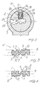
- the flat key is adapted for being used in cylindrical type of locks with a rotating rotor 2 in a stator 3.
- the flat key 6 has first and second means of engagement 5 and 7 which are lined up between themselves and lined up with at least a first and/or second interference organ 4 and 15, also lined up between themselves, in order to activate them so as to allow for rotation of the rotor 2 in the stator 3.
- the first means of engagement is defined by crests 30 which protrude from the plane 8 defined by at least one side face of the key 6 or which coincide with the plane 8 of one of the two side faces of the key 6.
- the second means of engagement 7 are, however, placed under the above-mentioned plane 8 and are defined by indentations 7, which extend towards the central axle of the key 6 included between the two side faces defined by the two planes 8, extracted from the structure of the key 6.
- the key 6 has, furthermore, third means of engagement, indicated as a whole with 9, adapted for activating only at least one third interference organ, generally indicated by 13, which is lined up with the first and second interference means 4 and 15 and cooperates with the latter to allow for the rotation of the rotor 2 within the stator 3.
- the third means of engagement 9 comprises at least one elevation 9 located on the face of the key sideways in alignment with the first, the second and the third interference organs.
- the elevation 9 has a first surface 10 which is substantially parallel to the face 8 of the key and at least a second inclined junction surface 11 of the first surface 10 with the face 8 of the key.
- the first surface 10, as indicated, only activates the third interference organ 13 to allow for rotation of the rotor 2 in the stator 3 of the lock.
- the elevation 9 may extend partially or along the entire length of the key.
- the elevation 9 includes at least one insert 12 with a configuration object substantially tapered, and in particular preferably of a conical configuration, adapted for engaging with the third interference organ 13 again to allow for rotation of the rotor 2 in the stator 3.
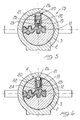
- the third interference organ 13 comprises a hollow glass 19 sutably with a truncated base 23, of a substantially truncated-conical configuration.
- a mobile element 20 aimed at moving in contrast with and activated by elastic means and in particular by a spring 25.
- the mobile element 20 has a lowered ring area 21 which allows for the wedging impaction of the mobile element with the edge of the glass 19, as illustrated for example in drawing 8.
- the mobile element 20 has a shaft 22 of a predefined length which extends from the lower area 21 towards the bottom of the glass 19.
- the first interference organ 4 unlike the third interference organ 13, comprises a hollow glass 19 with a conical base 24.
- a mobile element 20 which is identical to the mobile element 20 of the third interference organ 13 which moves internally within the hollow cable in contrast with or activated by elastic means in particular, a spring 25.
- the mobile element 20 has a lowered ring area 21 aimed at its wedging with the edge of the glass 19 and a shaft of a predefined length 22 which extends from the lowered area 21 towards the bottom of the glass.
- the first interference organ with regards to the third interference organ 13, is different due to its conical base 24 instead of the truncated-conical base 23 of the third interference organ 13.
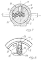
- the second interference organ 15 is however defined by a single structure 16, of a substantially cylindrical configuration, with its two opposing ends 17 of a substantially conical configuration.
- the first, the second and the third interference organs are placed in dedicated seats 18, all of which are the same, extracted from the rotor 2 in order to be placed in any position whatsoever in the seats 18.
- the mobile element will remain blocked between the bottom of the glass and the pocket 40 in which its head 26 is located, preventing rotation of the rotor with regards to the stator.
- the pin 13 tends to slope with regards to its axle (as illustrated in drawing 8) and wedging itself between the stator 3 and the rotor 2 by blocking the rotation of the latter with regards to the first and not allowing for the opening of the lock.
- annular area 21 of the pin can slide through the glass in contrast with or activated by the elastic means 25, thanks to the presence of the head 26 which the mobile element 20 is equipped with, therefore allowing for the rotation of the rotor 2.
- the shaft 22 is in contact with the conical base 24 of the glass 19 and the annular area 21 is within the glass 19.
- the invention reaches the objects proposed and achieves important and numerous advantages.
- the mechanical resistance of the key does not vary as the number of grooves which would weaken the key is not increased, but work is carried out beyond the plane defined, from at least one face of the key.
Landscapes
- Lock And Its Accessories (AREA)
- Push-Button Switches (AREA)
- Switches With Compound Operations (AREA)
Abstract
Description
- figure1 is a side view of a cylindrical lock according to the finding;
- figure2 is a front view of the lock including the rotor, stator and pin according to the finding;
- figure 3 is a sectionviewof the key according to the finding, in the presence of an elevation;
- figure 4 is a section view of the key according to the finding, in the presence of an insert;
- figure5 is a front section view of the lock with a pin with a truncated base and key inserted, according to the finding;
- figure 6 is a front section view of the lock with a pin with a conical base and with a key inserted, according to the finding;
- figure 7 is a front section view of the lock with pin made from a single structure and a key inserted, according to the finding;
- figure 8 is a front section view of the lock with pin in a blocking position to be rotated.
Claims (11)
- A flat key for a cylindrical lock, of the kind with a rotor rotating within a stator, comprising at least first and second means of engagement lined up between themselves and lined up with at least a first and/or second interference organ, also lined up between themselves, in order to activate them in a suitable manner to allow for the rotation of said rotor within said stator, said first means of engagement being defined by crests which protrude by at least one face of said key or which coincide with said face and said second means of commitment being defined by indentations placed below said face and extracted from the structure of said key, characterised in that it includes at least third means of commitment aimed at activating only at least one third interference organ, lined up with said first and second interference means, and cooperating with the latter to allow for rotation of said rotor within said stator.
- A key, according to claim 1, characterised in that e said third means of engagements comprises at least one elevation placed on said facesideways to the alignment of said first, second and third interference organs.
- A key, according to one or more of the previous claims, characterised in that said elevation has a first surface which is substantially parallel to the face of said key and at least a second inclined junction surface of said surface with said face.
- A key, according to one or more of the previous claims, characterised in that said first plane only activates said third interference organ to allow for the rotation of said rotor in said stator.
- A key, according to one or more of the previous claims, characterised in that said elevation extends develops along the entire length of said key.
- A key, according to one or more of the previous claims, characterised in that said elevation comprises at least one insert with a substantially tapered and preferably conical protrusion adapted for engaging with said third interference organ.
- A key, according to one or more of the previous claims, characterised in that said third interference organ comprises a hollow glass with a truncated base, of a substantially truncated-conical configuration, within which a mobile element is placed within said hollow glass in contrast with and activated by elastic means, said mobile element having a lower annular area adapted for wedging with the edge of said glass and with a shaft of a predefined length which extends from said lowered area towards the bottom of said glass.
- A key, according to one or more of the previous claims, characterised in that said first interference organ comprises a hollow glass with a conical base within which a mobile element is placed within said hollow glass in contrast with and activated by elastic means, said mobile element having a lower annular area adapted for wedging with the edge of said glass and a shaft of a predefined length which extends from said lowered area towards the bottom of said glass.
- A key, according to one or more of the previous claims, characterised in that said second interference organ has a body made from a single piece with two opposing extremities of a substantially conical configuration.
- A key, according to one or more of the previous claims, characterised in that said elevation engages with said glass with a truncated base of said third interference organ in a way suitable for its positioning with regards to the said mobile element to allow for its displacement within said glass for the rotation of said rotor with regards to said stator.
- A key, according to one or more of the previous claims, characterised in that said elevation engages with said glass with a conical base of said first interference organ in a way suitable for its positioning with regards to the said mobile element to prevent displacement of said mobile element within said glass due to the presence of said shaft in abutment with the bottom of said glass to prevent the rotation of said rotor with regards to said stator through the wedging of said mobile element with the edge of said glass.
Applications Claiming Priority (2)
| Application Number | Priority Date | Filing Date | Title |
|---|---|---|---|
| IT1999MI002561A IT1314115B1 (en) | 1999-12-10 | 1999-12-10 | FLAT KEY FOR CYLINDER LOCK. |
| ITMI992561 | 1999-12-10 |
Publications (3)
| Publication Number | Publication Date |
|---|---|
| EP1106756A2 true EP1106756A2 (en) | 2001-06-13 |
| EP1106756A3 EP1106756A3 (en) | 2001-12-12 |
| EP1106756B1 EP1106756B1 (en) | 2004-04-07 |
Family
ID=11384086
Family Applications (1)
| Application Number | Title | Priority Date | Filing Date |
|---|---|---|---|
| EP00126232A Expired - Lifetime EP1106756B1 (en) | 1999-12-10 | 2000-12-01 | Flat key and cylindrical lock |
Country Status (6)
| Country | Link |
|---|---|
| EP (1) | EP1106756B1 (en) |
| AT (1) | ATE263886T1 (en) |
| DE (1) | DE60009642T2 (en) |
| ES (1) | ES2219250T3 (en) |
| IT (1) | IT1314115B1 (en) |
| PT (1) | PT1106756E (en) |
Cited By (5)
| Publication number | Priority date | Publication date | Assignee | Title |
|---|---|---|---|---|
| EP1582662A1 (en) * | 2004-02-18 | 2005-10-05 | CISA S.p.A. | Lock with tamper-resistant elements and associated key |
| EP1593800A2 (en) | 2004-05-03 | 2005-11-09 | WILKA SCHLIESSTECHNIK GmbH | Locking device comprising a key and a lock cylinder |
| EP2022912A3 (en) * | 2007-08-06 | 2010-03-03 | Talleres De Escoriaza, S.A. | Key, for lock, with static inserts |
| WO2016098133A1 (en) * | 2014-12-15 | 2016-06-23 | Cisa S.P.A. | Cylinder lock and associated key |
| DE102022127488A1 (en) | 2022-01-17 | 2023-07-20 | C.Ed. Schulte Gesellschaft mit beschränkter Haftung Zylinderschlossfabrik | Process for profiling a flat key or flat key with an interrupted groove |
Families Citing this family (3)
| Publication number | Priority date | Publication date | Assignee | Title |
|---|---|---|---|---|
| DE102009039502A1 (en) | 2009-08-31 | 2011-03-24 | Iseo Deutschland Gmbh | flat key |
| DE102022109467A1 (en) | 2022-04-19 | 2023-10-19 | Dormakaba Austria Gmbh | LOCKING BOLT FOR ARRANGEMENT IN A LOCKING CYLINDER |
| WO2025191304A1 (en) * | 2024-03-13 | 2025-09-18 | Cisa S.P.A. | Cylinder lock and associated key |
Family Cites Families (8)
| Publication number | Priority date | Publication date | Assignee | Title |
|---|---|---|---|---|
| ES8503771A1 (en) * | 1984-05-18 | 1985-04-01 | Talleres Escoriaza Sa | A key for a lock |
| US4823575A (en) * | 1987-09-28 | 1989-04-25 | Bauer Kaba Ag | Cylinder lock and key |
| KR940002628B1 (en) * | 1990-02-17 | 1994-03-26 | 가부시끼가이샤 도시바 | Fan |
| AT396501B (en) * | 1991-07-02 | 1993-10-25 | Evva Werke | Cylinder lock with barring strips and flat key for the cylinder lock |
| ES2080649B1 (en) * | 1993-06-10 | 1999-05-16 | Cerrajera Ind | CYLINDER AND CORRESPONDING SECURITY KEY FOR LOCKS AND SIMILAR. |
| DE19522609A1 (en) * | 1995-06-22 | 1995-11-16 | Danijel Golub | Cylinder lock with security key |
| US5819567A (en) * | 1996-07-19 | 1998-10-13 | International Security Products, Inc. | Lock system with key trapping |
| ATE227385T1 (en) * | 1997-08-27 | 2002-11-15 | Iseo Serrature Spa | CYLINDER LOCK |
-
1999
- 1999-12-10 IT IT1999MI002561A patent/IT1314115B1/en active
-
2000
- 2000-12-01 EP EP00126232A patent/EP1106756B1/en not_active Expired - Lifetime
- 2000-12-01 ES ES00126232T patent/ES2219250T3/en not_active Expired - Lifetime
- 2000-12-01 DE DE60009642T patent/DE60009642T2/en not_active Expired - Lifetime
- 2000-12-01 AT AT00126232T patent/ATE263886T1/en active
- 2000-12-01 PT PT00126232T patent/PT1106756E/en unknown
Cited By (6)
| Publication number | Priority date | Publication date | Assignee | Title |
|---|---|---|---|---|
| EP1582662A1 (en) * | 2004-02-18 | 2005-10-05 | CISA S.p.A. | Lock with tamper-resistant elements and associated key |
| EP1593800A2 (en) | 2004-05-03 | 2005-11-09 | WILKA SCHLIESSTECHNIK GmbH | Locking device comprising a key and a lock cylinder |
| EP1593800A3 (en) * | 2004-05-03 | 2009-09-02 | WILKA SCHLIESSTECHNIK GmbH | Locking device comprising a key and a lock cylinder |
| EP2022912A3 (en) * | 2007-08-06 | 2010-03-03 | Talleres De Escoriaza, S.A. | Key, for lock, with static inserts |
| WO2016098133A1 (en) * | 2014-12-15 | 2016-06-23 | Cisa S.P.A. | Cylinder lock and associated key |
| DE102022127488A1 (en) | 2022-01-17 | 2023-07-20 | C.Ed. Schulte Gesellschaft mit beschränkter Haftung Zylinderschlossfabrik | Process for profiling a flat key or flat key with an interrupted groove |
Also Published As
| Publication number | Publication date |
|---|---|
| DE60009642D1 (en) | 2004-05-13 |
| ES2219250T3 (en) | 2004-12-01 |
| ITMI992561A0 (en) | 1999-12-10 |
| DE60009642T2 (en) | 2005-03-31 |
| EP1106756A3 (en) | 2001-12-12 |
| ATE263886T1 (en) | 2004-04-15 |
| IT1314115B1 (en) | 2002-12-04 |
| ITMI992561A1 (en) | 2001-06-10 |
| EP1106756B1 (en) | 2004-04-07 |
| PT1106756E (en) | 2004-08-31 |
Similar Documents
| Publication | Publication Date | Title |
|---|---|---|
| EP1106756B1 (en) | Flat key and cylindrical lock | |
| CA2681671C (en) | Hierarchical cylinder lock system | |
| AU2010206090B2 (en) | Profiled key for cylinder locks | |
| US20070286677A1 (en) | Manhole Cover Security Lock with Controlled Pressure Release | |
| JP2007506015A (en) | Key and lock system with special code combination | |
| AU2007258374A1 (en) | Manhole cover security lock with controlled pressure release | |
| US8485006B2 (en) | Disc tumbler cylinder lock and key combination | |
| TWI654360B (en) | Cylindrical lock | |
| CA3115369C (en) | A cylinder lock and key combination providing extra code combinations | |
| KR20070028597A (en) | Inflatable rivets | |
| ME01215B (en) | Key and disc tumbler cylinder lock | |
| US10428556B2 (en) | High security locking system which forms a deviating picking path and associated deviated key | |
| US8726706B2 (en) | Locking device | |
| JP4419149B2 (en) | Pressure cooker | |
| HU215769B (en) | Safety lock and flat key fitting to it | |
| US6170307B1 (en) | Pick-resistant lock system with improved cylinder construction | |
| CN111032230B (en) | Pump lock retention structure and method of using same | |
| JPH02236060A (en) | High pressure piston sealing device | |
| CN106869757B (en) | A kind of ground hook lock latching device | |
| US20180112502A1 (en) | Latch for a Ball and Sleeve Plunger | |
| CN206693898U (en) | A kind of ground hook lock latching device | |
| US20070018542A1 (en) | Cabinet safety device | |
| WO2011130123A2 (en) | Anchor system and method for anchoring a tool with a positional bias | |
| KR102102391B1 (en) | Pot bearing using eccentric rotational motion | |
| US20150267499A1 (en) | Modular Annular Debris Barrier with Rotationally Locked Segments |
Legal Events
| Date | Code | Title | Description |
|---|---|---|---|
| PUAI | Public reference made under article 153(3) epc to a published international application that has entered the european phase |
Free format text: ORIGINAL CODE: 0009012 |
|
| AK | Designated contracting states |
Kind code of ref document: A2 Designated state(s): AT BE CH CY DE DK ES FI FR GB GR IE IT LI LU MC NL PT SE TR |
|
| AX | Request for extension of the european patent |
Free format text: AL;LT;LV;MK;RO;SI |
|
| PUAL | Search report despatched |
Free format text: ORIGINAL CODE: 0009013 |
|
| AK | Designated contracting states |
Kind code of ref document: A3 Designated state(s): AT BE CH CY DE DK ES FI FR GB GR IE IT LI LU MC NL PT SE TR |
|
| AX | Request for extension of the european patent |
Free format text: AL;LT;LV;MK;RO;SI |
|
| RIC1 | Information provided on ipc code assigned before grant |
Free format text: 7E 05B 19/00 A, 7E 05B 27/00 B |
|
| 17P | Request for examination filed |
Effective date: 20020423 |
|
| AKX | Designation fees paid |
Free format text: AT BE CH CY DE DK ES FI FR GB GR IE IT LI LU MC NL PT SE TR |
|
| 17Q | First examination report despatched |
Effective date: 20020926 |
|
| RTI1 | Title (correction) |
Free format text: FLAT KEY AND CYLINDRICAL LOCK |
|
| GRAP | Despatch of communication of intention to grant a patent |
Free format text: ORIGINAL CODE: EPIDOSNIGR1 |
|
| GRAS | Grant fee paid |
Free format text: ORIGINAL CODE: EPIDOSNIGR3 |
|
| GRAA | (expected) grant |
Free format text: ORIGINAL CODE: 0009210 |
|
| AK | Designated contracting states |
Kind code of ref document: B1 Designated state(s): AT BE CH CY DE DK ES FI FR GB GR IE IT LI LU MC NL PT SE TR |
|
| PG25 | Lapsed in a contracting state [announced via postgrant information from national office to epo] |
Ref country code: CY Free format text: LAPSE BECAUSE OF FAILURE TO SUBMIT A TRANSLATION OF THE DESCRIPTION OR TO PAY THE FEE WITHIN THE PRESCRIBED TIME-LIMIT Effective date: 20040407 Ref country code: TR Free format text: LAPSE BECAUSE OF FAILURE TO SUBMIT A TRANSLATION OF THE DESCRIPTION OR TO PAY THE FEE WITHIN THE PRESCRIBED TIME-LIMIT Effective date: 20040407 Ref country code: LI Free format text: LAPSE BECAUSE OF FAILURE TO SUBMIT A TRANSLATION OF THE DESCRIPTION OR TO PAY THE FEE WITHIN THE PRESCRIBED TIME-LIMIT Effective date: 20040407 Ref country code: CH Free format text: LAPSE BECAUSE OF FAILURE TO SUBMIT A TRANSLATION OF THE DESCRIPTION OR TO PAY THE FEE WITHIN THE PRESCRIBED TIME-LIMIT Effective date: 20040407 Ref country code: FI Free format text: LAPSE BECAUSE OF FAILURE TO SUBMIT A TRANSLATION OF THE DESCRIPTION OR TO PAY THE FEE WITHIN THE PRESCRIBED TIME-LIMIT Effective date: 20040407 |
|
| REG | Reference to a national code |
Ref country code: GB Ref legal event code: FG4D |
|
| REG | Reference to a national code |
Ref country code: CH Ref legal event code: EP |
|
| REF | Corresponds to: |
Ref document number: 60009642 Country of ref document: DE Date of ref document: 20040513 Kind code of ref document: P |
|
| REG | Reference to a national code |
Ref country code: IE Ref legal event code: FG4D |
|
| PG25 | Lapsed in a contracting state [announced via postgrant information from national office to epo] |
Ref country code: SE Free format text: LAPSE BECAUSE OF FAILURE TO SUBMIT A TRANSLATION OF THE DESCRIPTION OR TO PAY THE FEE WITHIN THE PRESCRIBED TIME-LIMIT Effective date: 20040707 Ref country code: DK Free format text: LAPSE BECAUSE OF FAILURE TO SUBMIT A TRANSLATION OF THE DESCRIPTION OR TO PAY THE FEE WITHIN THE PRESCRIBED TIME-LIMIT Effective date: 20040707 Ref country code: GR Free format text: LAPSE BECAUSE OF FAILURE TO SUBMIT A TRANSLATION OF THE DESCRIPTION OR TO PAY THE FEE WITHIN THE PRESCRIBED TIME-LIMIT Effective date: 20040707 |
|
| REG | Reference to a national code |
Ref country code: PT Ref legal event code: SC4A Free format text: AVAILABILITY OF NATIONAL TRANSLATION Effective date: 20040706 |
|
| REG | Reference to a national code |
Ref country code: CH Ref legal event code: PL |
|
| PG25 | Lapsed in a contracting state [announced via postgrant information from national office to epo] |
Ref country code: LU Free format text: LAPSE BECAUSE OF NON-PAYMENT OF DUE FEES Effective date: 20041201 Ref country code: IE Free format text: LAPSE BECAUSE OF NON-PAYMENT OF DUE FEES Effective date: 20041201 |
|
| REG | Reference to a national code |
Ref country code: ES Ref legal event code: FG2A Ref document number: 2219250 Country of ref document: ES Kind code of ref document: T3 |
|
| PG25 | Lapsed in a contracting state [announced via postgrant information from national office to epo] |
Ref country code: MC Free format text: LAPSE BECAUSE OF NON-PAYMENT OF DUE FEES Effective date: 20041231 |
|
| ET | Fr: translation filed | ||
| PLBE | No opposition filed within time limit |
Free format text: ORIGINAL CODE: 0009261 |
|
| STAA | Information on the status of an ep patent application or granted ep patent |
Free format text: STATUS: NO OPPOSITION FILED WITHIN TIME LIMIT |
|
| 26N | No opposition filed |
Effective date: 20050110 |
|
| REG | Reference to a national code |
Ref country code: IE Ref legal event code: MM4A |
|
| PG25 | Lapsed in a contracting state [announced via postgrant information from national office to epo] |
Ref country code: IT Free format text: LAPSE BECAUSE OF NON-PAYMENT OF DUE FEES Effective date: 20071201 |
|
| REG | Reference to a national code |
Ref country code: FR Ref legal event code: PLFP Year of fee payment: 16 |
|
| REG | Reference to a national code |
Ref country code: FR Ref legal event code: PLFP Year of fee payment: 17 |
|
| REG | Reference to a national code |
Ref country code: FR Ref legal event code: PLFP Year of fee payment: 18 |
|
| PGFP | Annual fee paid to national office [announced via postgrant information from national office to epo] |
Ref country code: PT Payment date: 20191202 Year of fee payment: 20 Ref country code: NL Payment date: 20191223 Year of fee payment: 20 |
|
| PGFP | Annual fee paid to national office [announced via postgrant information from national office to epo] |
Ref country code: BE Payment date: 20191223 Year of fee payment: 20 Ref country code: IT Payment date: 20191212 Year of fee payment: 20 Ref country code: FR Payment date: 20191230 Year of fee payment: 20 |
|
| PGFP | Annual fee paid to national office [announced via postgrant information from national office to epo] |
Ref country code: AT Payment date: 20191220 Year of fee payment: 20 |
|
| PGFP | Annual fee paid to national office [announced via postgrant information from national office to epo] |
Ref country code: GB Payment date: 20191212 Year of fee payment: 20 Ref country code: DE Payment date: 20191230 Year of fee payment: 20 Ref country code: ES Payment date: 20200123 Year of fee payment: 20 |
|
| REG | Reference to a national code |
Ref country code: DE Ref legal event code: R071 Ref document number: 60009642 Country of ref document: DE |
|
| REG | Reference to a national code |
Ref country code: NL Ref legal event code: MK Effective date: 20201130 |
|
| REG | Reference to a national code |
Ref country code: GB Ref legal event code: PE20 Expiry date: 20201130 |
|
| REG | Reference to a national code |
Ref country code: AT Ref legal event code: MK07 Ref document number: 263886 Country of ref document: AT Kind code of ref document: T Effective date: 20201201 |
|
| PG25 | Lapsed in a contracting state [announced via postgrant information from national office to epo] |
Ref country code: GB Free format text: LAPSE BECAUSE OF EXPIRATION OF PROTECTION Effective date: 20201130 Ref country code: PT Free format text: LAPSE BECAUSE OF EXPIRATION OF PROTECTION Effective date: 20201216 |
|
| REG | Reference to a national code |
Ref country code: BE Ref legal event code: MK Effective date: 20201201 |
|
| REG | Reference to a national code |
Ref country code: ES Ref legal event code: FD2A Effective date: 20211230 |
|
| PG25 | Lapsed in a contracting state [announced via postgrant information from national office to epo] |
Ref country code: ES Free format text: LAPSE BECAUSE OF EXPIRATION OF PROTECTION Effective date: 20201202 |