EP1106460A2 - A control method - Google Patents
A control method Download PDFInfo
- Publication number
- EP1106460A2 EP1106460A2 EP00124009A EP00124009A EP1106460A2 EP 1106460 A2 EP1106460 A2 EP 1106460A2 EP 00124009 A EP00124009 A EP 00124009A EP 00124009 A EP00124009 A EP 00124009A EP 1106460 A2 EP1106460 A2 EP 1106460A2
- Authority
- EP
- European Patent Office
- Prior art keywords
- estimated
- torque
- wheel
- speed
- function
- Prior art date
- Legal status (The legal status is an assumption and is not a legal conclusion. Google has not performed a legal analysis and makes no representation as to the accuracy of the status listed.)
- Withdrawn
Links
- 238000000034 method Methods 0.000 title claims abstract description 24
- 238000005259 measurement Methods 0.000 description 4
- 238000010586 diagram Methods 0.000 description 2
- 230000001133 acceleration Effects 0.000 description 1
- 238000009499 grossing Methods 0.000 description 1
- 230000010354 integration Effects 0.000 description 1
- 238000012986 modification Methods 0.000 description 1
- 230000004048 modification Effects 0.000 description 1
Images
Classifications
-
- G—PHYSICS
- G01—MEASURING; TESTING
- G01P—MEASURING LINEAR OR ANGULAR SPEED, ACCELERATION, DECELERATION, OR SHOCK; INDICATING PRESENCE, ABSENCE, OR DIRECTION, OF MOVEMENT
- G01P3/00—Measuring linear or angular speed; Measuring differences of linear or angular speeds
-
- B—PERFORMING OPERATIONS; TRANSPORTING
- B60—VEHICLES IN GENERAL
- B60T—VEHICLE BRAKE CONTROL SYSTEMS OR PARTS THEREOF; BRAKE CONTROL SYSTEMS OR PARTS THEREOF, IN GENERAL; ARRANGEMENT OF BRAKING ELEMENTS ON VEHICLES IN GENERAL; PORTABLE DEVICES FOR PREVENTING UNWANTED MOVEMENT OF VEHICLES; VEHICLE MODIFICATIONS TO FACILITATE COOLING OF BRAKES
- B60T8/00—Arrangements for adjusting wheel-braking force to meet varying vehicular or ground-surface conditions, e.g. limiting or varying distribution of braking force
- B60T8/17—Using electrical or electronic regulation means to control braking
- B60T8/172—Determining control parameters used in the regulation, e.g. by calculations involving measured or detected parameters
Definitions
- This invention relates to control methods and in particular, but not exclusively, to a control method for deriving the wheel speed of a vehicle.
- Some known wheel speed measurement devices for vehicles employ a pick-up transducer and target wheel arrangement.
- a significant lag can sometimes be introduced into the feedback signal, e.g. if a low number of targets is used with a consequent high level of signal smoothing.
- the invention provides a control method suitable for providing a signal indicative of a wheel speed for a control system of a vehicle, the method including the step of estimating the speed of a wheel as a function of the torque applied thereto and an estimated resistive torque.
- the method may include applying a lag to the estimated wheel speed and deriving the difference between the lagging estimated speed and a measured wheel speed, so as to produce a function which is indicative of the difference between the actual resistive torque and the estimated torque.
- the method may include applying a proportional gain so as to estimate the resistive torque as a function of an error signal.
- the invention also provides a vehicle including a control system arranged to operate according to the method of the invention.
- Said control system may comprise a terrain recognition system or a flat tyre warning system.
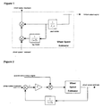
- one method of dealing with a feedback signal delay is to employ a "Smith Predictor" arrangement.
- Such an arrangement is shown in Figure 1 and is discussed in "The Art of Control Engineering”; Dutton, K et al.; Addison Wesley, 1997.
- This arrangement is based on a predictive model of a plant's behaviour for a known input.
- the arrangement can be adapted to negate the effects of a feedback lag by modelling the behaviour of an ideal plant and predicting the feedback signal through the application of a lag.
- wheel speed For vehicles, this approach is suitable for wheel speed measurement where a lag can occur in the signal feedback.
- a wheel can be considered as a simple inertia and, when a known torque is applied to the wheel, then wheel acceleration can be modelled using equation (1) below. From this, wheel speed can be obtained by integration.
- Jw is the wheel inertia
- ⁇ app is the applied torque from the drive train
- ⁇ res is the resistive torque acting on the wheel.
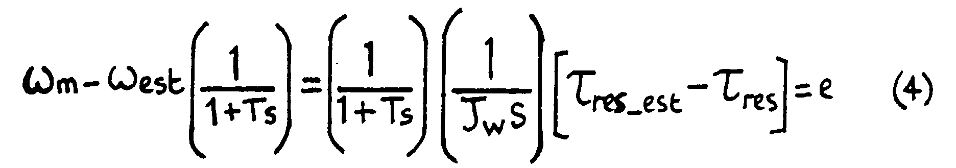
- the resistive torque ⁇ res acting on the wheel is a function of the load on the wheel and the terrain. A direct measurement of this torque is difficult using current methods in the automotive art and the method of the present invention provides a method of inferring the resistive torque ⁇ res acting on the wheel by using the measured wheel speed ⁇ m and an estimated wheel speed ⁇ est .
- the method of the present invention is explained now with particular reference to Figure 2.
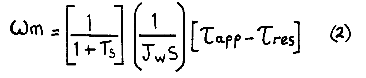
- the measured wheel speed ⁇ m can be represented by equation (2), shown below.
- T represents the time constant associated with a measurement time lag denoted by (1/1+T s )
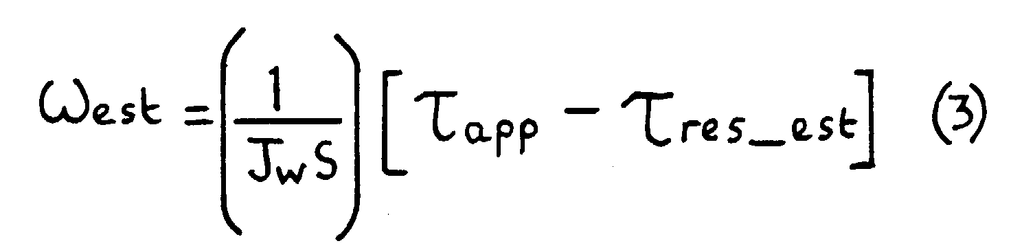
- An estimated wheel speed ⁇ est is calculated as a function of ⁇ app (known) and an estimated resistive torque ⁇ res_est using equation (3).
- the resistive torque estimation can use a "Proportional + Integral” (PI) or “Proportional, Integral & Derivative” (PID) gain as appropriate.
- PI Proportional + Integral
- PID Proportional, Integral & Derivative
- the wheel load estimate can be used as part of a terrain recognition system of, for example, an off-road vehicle. It could also be adapted for providing a vehicle user with a warning of low tyre pressure.
Landscapes
- Engineering & Computer Science (AREA)
- Physics & Mathematics (AREA)
- General Physics & Mathematics (AREA)
- Transportation (AREA)
- Mechanical Engineering (AREA)
- Regulating Braking Force (AREA)
- Control Of Driving Devices And Active Controlling Of Vehicle (AREA)
- Vehicle Body Suspensions (AREA)
Abstract
Description

Claims (6)
- A control method suitable for providing a signal indicative of a wheel speed for a control system of a vehicle, the method including the step of estimating the speed of a wheel as a function of the torque applied thereto and an estimated resistive torque.
- A method according to Claim 1, including applying a lag to the estimated wheel speed and deriving the difference between the lagging estimated speed and a measured wheel speed, so as to produce a function which is indicative of the difference between the actual resistive torque and the estimated torque.
- A method according to Claim 2, including applying a proportional gain so as to estimate the resistive torque as a function of an error signal.
- A method substantially as described herein and with reference to Figure 2 of the accompanying drawings.
- A vehicle including a control system arranged to operate according to the method of any preceding claim.
- A vehicle according to Claim 5, said control system comprising a terrain recognition system or a flat tyre warning system.
Applications Claiming Priority (2)
| Application Number | Priority Date | Filing Date | Title |
|---|---|---|---|
| GB9928767 | 1999-12-07 | ||
| GB9928767A GB2357147A (en) | 1999-12-07 | 1999-12-07 | Estimating wheel speed as a function of applied torque and estimated resistive torque |
Publications (2)
| Publication Number | Publication Date |
|---|---|
| EP1106460A2 true EP1106460A2 (en) | 2001-06-13 |
| EP1106460A3 EP1106460A3 (en) | 2002-07-31 |
Family
ID=10865765
Family Applications (1)
| Application Number | Title | Priority Date | Filing Date |
|---|---|---|---|
| EP00124009A Withdrawn EP1106460A3 (en) | 1999-12-07 | 2000-11-04 | A control method |
Country Status (2)
| Country | Link |
|---|---|
| EP (1) | EP1106460A3 (en) |
| GB (1) | GB2357147A (en) |
Cited By (2)
| Publication number | Priority date | Publication date | Assignee | Title |
|---|---|---|---|---|
| CN100432672C (en) * | 2003-11-20 | 2008-11-12 | 丰田自动车株式会社 | Vehicle travel control device and vehicle travel control method |
| WO2017202135A1 (en) * | 2016-05-25 | 2017-11-30 | 比亚迪股份有限公司 | Control method for when vehicle has flat tire, vehicle control system and vehicle |
Families Citing this family (2)
| Publication number | Priority date | Publication date | Assignee | Title |
|---|---|---|---|---|
| CN110758027A (en) * | 2019-10-17 | 2020-02-07 | 江苏徐工工程机械研究院有限公司 | Hydraulic transmission wheel type engineering machinery tire pressure monitoring and early warning method |
| CN112603205B (en) * | 2020-12-17 | 2022-01-04 | 珠海一微半导体股份有限公司 | Robot walking speed adjusting method |
Family Cites Families (10)
| Publication number | Priority date | Publication date | Assignee | Title |
|---|---|---|---|---|
| US4260942A (en) * | 1978-04-17 | 1981-04-07 | Trw Inc. | Failure detection and correction system for redundant control elements |
| JPS60189666A (en) * | 1984-03-07 | 1985-09-27 | Nippon Denso Co Ltd | Nonslip device for vehicles |
| EP0550997A1 (en) * | 1992-01-10 | 1993-07-14 | Lucas Industries Public Limited Company | Method of and apparatus for detecting wheel spin |
| US5452207A (en) * | 1992-11-09 | 1995-09-19 | Ford Motor Company | Robust torque estimation using multiple models |
| JPH07324641A (en) * | 1994-04-07 | 1995-12-12 | Mitsubishi Motors Corp | Vehicle driving force control device |
| US5515279A (en) * | 1995-03-06 | 1996-05-07 | Ford Motor Company | Method and apparatus controlling cross-axis oscillations in a vehicle traction controller |
| KR970066191A (en) * | 1996-03-01 | 1997-10-13 | 가나이 쯔도무 | Control device and control method of automatic transmission |
| US6220676B1 (en) * | 1997-05-09 | 2001-04-24 | The B. F. Goodrich Company | Antiskid control of multi-wheel vehicles using coupled and decoupled Kalman filtering incorporating pitch weight transfer |
| US5951122A (en) * | 1997-12-31 | 1999-09-14 | The B.F. Goodrich Company | Antiskid control and wheel lock protection differential reference controller |
| JP3617309B2 (en) * | 1998-05-27 | 2005-02-02 | 日産自動車株式会社 | Road friction coefficient estimation device |
-
1999
- 1999-12-07 GB GB9928767A patent/GB2357147A/en not_active Withdrawn
-
2000
- 2000-11-04 EP EP00124009A patent/EP1106460A3/en not_active Withdrawn
Non-Patent Citations (1)
| Title |
|---|
| None |
Cited By (3)
| Publication number | Priority date | Publication date | Assignee | Title |
|---|---|---|---|---|
| CN100432672C (en) * | 2003-11-20 | 2008-11-12 | 丰田自动车株式会社 | Vehicle travel control device and vehicle travel control method |
| WO2017202135A1 (en) * | 2016-05-25 | 2017-11-30 | 比亚迪股份有限公司 | Control method for when vehicle has flat tire, vehicle control system and vehicle |
| US10953868B2 (en) | 2016-05-25 | 2021-03-23 | Byd Company Limited | Control method when vehicle tire bursts, vehicle control system and vehicle |
Also Published As
| Publication number | Publication date |
|---|---|
| EP1106460A3 (en) | 2002-07-31 |
| GB2357147A (en) | 2001-06-13 |
| GB9928767D0 (en) | 2000-02-02 |
Similar Documents
| Publication | Publication Date | Title |
|---|---|---|
| KR100412674B1 (en) | The method for estimating the friction coefficient between tires and road surfaces for calculating flexible safe following distance of the vehicle | |
| US6351694B1 (en) | Method for robust estimation of road bank angle | |
| JP4583028B2 (en) | Method for estimating the mass of a vehicle driven on a road with varying slope and method for estimating the slope of a road | |
| EP2694344B1 (en) | Estimation of road inclination | |
| Castillo et al. | A novel electrohydraulic brake system with tire–road friction estimation and continuous brake pressure control | |
| EP2187223B1 (en) | System and method for compensating vehicle sensor signals | |
| US6816804B1 (en) | System and method for estimating velocity using reliability indexed sensor fusion | |
| US20040193345A1 (en) | Active steering for handling/stability enhancement | |
| JP2019513613A (en) | Method, system and non-transitory computer readable memory for controlling a vehicle | |
| KR20200031211A (en) | System and method for estimating wheel speed of vehicle | |
| KR20180109881A (en) | Tire stiffness estimation and road friction estimation | |
| US20170306874A1 (en) | Vehicle driver model | |
| KR100503397B1 (en) | Method and device for monitoring sensors in a vehicle | |
| EP1106460A2 (en) | A control method | |
| EP4197821A1 (en) | Tire stiffness estimation system and method | |
| EP3760986A1 (en) | Method for estimating the mass of an off road vehicle and a related off-road vehicle | |
| JPH11208494A (en) | Automatic vehicle steering system | |
| CN116348347A (en) | Method for controlling torque of at least one wheel | |
| JP2010532295A (en) | Processing method of signal transmitted from position sensor of automobile control member | |
| US20240369592A1 (en) | Method for estimating the reference speed of a vehicle for limit conditions | |
| JP7783575B2 (en) | Vehicle control device | |
| KR20000068360A (en) | Method and device for monitoring sensors in a vehicle | |
| EP3583021B1 (en) | System for estimating the slope of a pedal-assisted bicycle | |
| JP3271955B2 (en) | Road surface friction coefficient estimation device for vehicles | |
| US20060247838A1 (en) | Method for detecting a real value of a manipulated variable, particularity of a steering angle |
Legal Events
| Date | Code | Title | Description |
|---|---|---|---|
| PUAI | Public reference made under article 153(3) epc to a published international application that has entered the european phase |
Free format text: ORIGINAL CODE: 0009012 |
|
| AK | Designated contracting states |
Kind code of ref document: A2 Designated state(s): AT BE CH CY DE DK ES FI FR GB GR IE IT LI LU MC NL PT SE TR |
|
| AX | Request for extension of the european patent |
Free format text: AL;LT;LV;MK;RO;SI |
|
| PUAL | Search report despatched |
Free format text: ORIGINAL CODE: 0009013 |
|
| RAP1 | Party data changed (applicant data changed or rights of an application transferred) |
Owner name: BAYERISCHE MOTOREN WERKE AKTIENGESELLSCHAFT |
|
| AK | Designated contracting states |
Kind code of ref document: A3 Designated state(s): AT BE CH CY DE DK ES FI FR GB GR IE IT LI LU MC NL PT SE TR |
|
| AX | Request for extension of the european patent |
Free format text: AL;LT;LV;MK;RO;SI |
|
| RIC1 | Information provided on ipc code assigned before grant |
Free format text: 7B 60T 8/00 A, 7G 01P 3/00 B |
|
| 17P | Request for examination filed |
Effective date: 20020914 |
|
| AKX | Designation fees paid |
Designated state(s): DE FR GB |
|
| 17Q | First examination report despatched |
Effective date: 20030709 |
|
| STAA | Information on the status of an ep patent application or granted ep patent |
Free format text: STATUS: THE APPLICATION HAS BEEN WITHDRAWN |
|
| 18W | Application withdrawn |
Effective date: 20031111 |