EP1106412A2 - Hybrid power output apparatus and method for controlling motor / generator to lock planetary gearing elements - Google Patents
Hybrid power output apparatus and method for controlling motor / generator to lock planetary gearing elements Download PDFInfo
- Publication number
- EP1106412A2 EP1106412A2 EP01108622A EP01108622A EP1106412A2 EP 1106412 A2 EP1106412 A2 EP 1106412A2 EP 01108622 A EP01108622 A EP 01108622A EP 01108622 A EP01108622 A EP 01108622A EP 1106412 A2 EP1106412 A2 EP 1106412A2
- Authority
- EP
- European Patent Office
- Prior art keywords
- power
- motor
- output
- engine
- torque
- Prior art date
- Legal status (The legal status is an assumption and is not a legal conclusion. Google has not performed a legal analysis and makes no representation as to the accuracy of the status listed.)
- Granted
Links
Images


Classifications
-
- B—PERFORMING OPERATIONS; TRANSPORTING
- B60—VEHICLES IN GENERAL
- B60W—CONJOINT CONTROL OF VEHICLE SUB-UNITS OF DIFFERENT TYPE OR DIFFERENT FUNCTION; CONTROL SYSTEMS SPECIALLY ADAPTED FOR HYBRID VEHICLES; ROAD VEHICLE DRIVE CONTROL SYSTEMS FOR PURPOSES NOT RELATED TO THE CONTROL OF A PARTICULAR SUB-UNIT
- B60W20/00—Control systems specially adapted for hybrid vehicles
- B60W20/10—Controlling the power contribution of each of the prime movers to meet required power demand
- B60W20/11—Controlling the power contribution of each of the prime movers to meet required power demand using model predictive control [MPC] strategies, i.e. control methods based on models predicting performance
-
- B—PERFORMING OPERATIONS; TRANSPORTING
- B60—VEHICLES IN GENERAL
- B60K—ARRANGEMENT OR MOUNTING OF PROPULSION UNITS OR OF TRANSMISSIONS IN VEHICLES; ARRANGEMENT OR MOUNTING OF PLURAL DIVERSE PRIME-MOVERS IN VEHICLES; AUXILIARY DRIVES FOR VEHICLES; INSTRUMENTATION OR DASHBOARDS FOR VEHICLES; ARRANGEMENTS IN CONNECTION WITH COOLING, AIR INTAKE, GAS EXHAUST OR FUEL SUPPLY OF PROPULSION UNITS IN VEHICLES
- B60K6/00—Arrangement or mounting of plural diverse prime-movers for mutual or common propulsion, e.g. hybrid propulsion systems comprising electric motors and internal combustion engines ; Control systems therefor, i.e. systems controlling two or more prime movers, or controlling one of these prime movers and any of the transmission, drive or drive units Informative references: mechanical gearings with secondary electric drive F16H3/72; arrangements for handling mechanical energy structurally associated with the dynamo-electric machine H02K7/00; machines comprising structurally interrelated motor and generator parts H02K51/00; dynamo-electric machines not otherwise provided for in H02K see H02K99/00
- B60K6/20—Arrangement or mounting of plural diverse prime-movers for mutual or common propulsion, e.g. hybrid propulsion systems comprising electric motors and internal combustion engines ; Control systems therefor, i.e. systems controlling two or more prime movers, or controlling one of these prime movers and any of the transmission, drive or drive units Informative references: mechanical gearings with secondary electric drive F16H3/72; arrangements for handling mechanical energy structurally associated with the dynamo-electric machine H02K7/00; machines comprising structurally interrelated motor and generator parts H02K51/00; dynamo-electric machines not otherwise provided for in H02K see H02K99/00 the prime-movers consisting of electric motors and internal combustion engines, e.g. HEVs
- B60K6/22—Arrangement or mounting of plural diverse prime-movers for mutual or common propulsion, e.g. hybrid propulsion systems comprising electric motors and internal combustion engines ; Control systems therefor, i.e. systems controlling two or more prime movers, or controlling one of these prime movers and any of the transmission, drive or drive units Informative references: mechanical gearings with secondary electric drive F16H3/72; arrangements for handling mechanical energy structurally associated with the dynamo-electric machine H02K7/00; machines comprising structurally interrelated motor and generator parts H02K51/00; dynamo-electric machines not otherwise provided for in H02K see H02K99/00 the prime-movers consisting of electric motors and internal combustion engines, e.g. HEVs characterised by apparatus, components or means specially adapted for HEVs
- B60K6/36—Arrangement or mounting of plural diverse prime-movers for mutual or common propulsion, e.g. hybrid propulsion systems comprising electric motors and internal combustion engines ; Control systems therefor, i.e. systems controlling two or more prime movers, or controlling one of these prime movers and any of the transmission, drive or drive units Informative references: mechanical gearings with secondary electric drive F16H3/72; arrangements for handling mechanical energy structurally associated with the dynamo-electric machine H02K7/00; machines comprising structurally interrelated motor and generator parts H02K51/00; dynamo-electric machines not otherwise provided for in H02K see H02K99/00 the prime-movers consisting of electric motors and internal combustion engines, e.g. HEVs characterised by apparatus, components or means specially adapted for HEVs characterised by the transmission gearings
- B60K6/365—Arrangement or mounting of plural diverse prime-movers for mutual or common propulsion, e.g. hybrid propulsion systems comprising electric motors and internal combustion engines ; Control systems therefor, i.e. systems controlling two or more prime movers, or controlling one of these prime movers and any of the transmission, drive or drive units Informative references: mechanical gearings with secondary electric drive F16H3/72; arrangements for handling mechanical energy structurally associated with the dynamo-electric machine H02K7/00; machines comprising structurally interrelated motor and generator parts H02K51/00; dynamo-electric machines not otherwise provided for in H02K see H02K99/00 the prime-movers consisting of electric motors and internal combustion engines, e.g. HEVs characterised by apparatus, components or means specially adapted for HEVs characterised by the transmission gearings with the gears having orbital motion
-
- B—PERFORMING OPERATIONS; TRANSPORTING
- B60—VEHICLES IN GENERAL
- B60K—ARRANGEMENT OR MOUNTING OF PROPULSION UNITS OR OF TRANSMISSIONS IN VEHICLES; ARRANGEMENT OR MOUNTING OF PLURAL DIVERSE PRIME-MOVERS IN VEHICLES; AUXILIARY DRIVES FOR VEHICLES; INSTRUMENTATION OR DASHBOARDS FOR VEHICLES; ARRANGEMENTS IN CONNECTION WITH COOLING, AIR INTAKE, GAS EXHAUST OR FUEL SUPPLY OF PROPULSION UNITS IN VEHICLES
- B60K6/00—Arrangement or mounting of plural diverse prime-movers for mutual or common propulsion, e.g. hybrid propulsion systems comprising electric motors and internal combustion engines ; Control systems therefor, i.e. systems controlling two or more prime movers, or controlling one of these prime movers and any of the transmission, drive or drive units Informative references: mechanical gearings with secondary electric drive F16H3/72; arrangements for handling mechanical energy structurally associated with the dynamo-electric machine H02K7/00; machines comprising structurally interrelated motor and generator parts H02K51/00; dynamo-electric machines not otherwise provided for in H02K see H02K99/00
- B60K6/20—Arrangement or mounting of plural diverse prime-movers for mutual or common propulsion, e.g. hybrid propulsion systems comprising electric motors and internal combustion engines ; Control systems therefor, i.e. systems controlling two or more prime movers, or controlling one of these prime movers and any of the transmission, drive or drive units Informative references: mechanical gearings with secondary electric drive F16H3/72; arrangements for handling mechanical energy structurally associated with the dynamo-electric machine H02K7/00; machines comprising structurally interrelated motor and generator parts H02K51/00; dynamo-electric machines not otherwise provided for in H02K see H02K99/00 the prime-movers consisting of electric motors and internal combustion engines, e.g. HEVs
- B60K6/22—Arrangement or mounting of plural diverse prime-movers for mutual or common propulsion, e.g. hybrid propulsion systems comprising electric motors and internal combustion engines ; Control systems therefor, i.e. systems controlling two or more prime movers, or controlling one of these prime movers and any of the transmission, drive or drive units Informative references: mechanical gearings with secondary electric drive F16H3/72; arrangements for handling mechanical energy structurally associated with the dynamo-electric machine H02K7/00; machines comprising structurally interrelated motor and generator parts H02K51/00; dynamo-electric machines not otherwise provided for in H02K see H02K99/00 the prime-movers consisting of electric motors and internal combustion engines, e.g. HEVs characterised by apparatus, components or means specially adapted for HEVs
- B60K6/40—Arrangement or mounting of plural diverse prime-movers for mutual or common propulsion, e.g. hybrid propulsion systems comprising electric motors and internal combustion engines ; Control systems therefor, i.e. systems controlling two or more prime movers, or controlling one of these prime movers and any of the transmission, drive or drive units Informative references: mechanical gearings with secondary electric drive F16H3/72; arrangements for handling mechanical energy structurally associated with the dynamo-electric machine H02K7/00; machines comprising structurally interrelated motor and generator parts H02K51/00; dynamo-electric machines not otherwise provided for in H02K see H02K99/00 the prime-movers consisting of electric motors and internal combustion engines, e.g. HEVs characterised by apparatus, components or means specially adapted for HEVs characterised by the assembly or relative disposition of components
-
- B—PERFORMING OPERATIONS; TRANSPORTING
- B60—VEHICLES IN GENERAL
- B60K—ARRANGEMENT OR MOUNTING OF PROPULSION UNITS OR OF TRANSMISSIONS IN VEHICLES; ARRANGEMENT OR MOUNTING OF PLURAL DIVERSE PRIME-MOVERS IN VEHICLES; AUXILIARY DRIVES FOR VEHICLES; INSTRUMENTATION OR DASHBOARDS FOR VEHICLES; ARRANGEMENTS IN CONNECTION WITH COOLING, AIR INTAKE, GAS EXHAUST OR FUEL SUPPLY OF PROPULSION UNITS IN VEHICLES
- B60K6/00—Arrangement or mounting of plural diverse prime-movers for mutual or common propulsion, e.g. hybrid propulsion systems comprising electric motors and internal combustion engines ; Control systems therefor, i.e. systems controlling two or more prime movers, or controlling one of these prime movers and any of the transmission, drive or drive units Informative references: mechanical gearings with secondary electric drive F16H3/72; arrangements for handling mechanical energy structurally associated with the dynamo-electric machine H02K7/00; machines comprising structurally interrelated motor and generator parts H02K51/00; dynamo-electric machines not otherwise provided for in H02K see H02K99/00
- B60K6/20—Arrangement or mounting of plural diverse prime-movers for mutual or common propulsion, e.g. hybrid propulsion systems comprising electric motors and internal combustion engines ; Control systems therefor, i.e. systems controlling two or more prime movers, or controlling one of these prime movers and any of the transmission, drive or drive units Informative references: mechanical gearings with secondary electric drive F16H3/72; arrangements for handling mechanical energy structurally associated with the dynamo-electric machine H02K7/00; machines comprising structurally interrelated motor and generator parts H02K51/00; dynamo-electric machines not otherwise provided for in H02K see H02K99/00 the prime-movers consisting of electric motors and internal combustion engines, e.g. HEVs
- B60K6/42—Arrangement or mounting of plural diverse prime-movers for mutual or common propulsion, e.g. hybrid propulsion systems comprising electric motors and internal combustion engines ; Control systems therefor, i.e. systems controlling two or more prime movers, or controlling one of these prime movers and any of the transmission, drive or drive units Informative references: mechanical gearings with secondary electric drive F16H3/72; arrangements for handling mechanical energy structurally associated with the dynamo-electric machine H02K7/00; machines comprising structurally interrelated motor and generator parts H02K51/00; dynamo-electric machines not otherwise provided for in H02K see H02K99/00 the prime-movers consisting of electric motors and internal combustion engines, e.g. HEVs characterised by the architecture of the hybrid electric vehicle
- B60K6/44—Series-parallel type
- B60K6/445—Differential gearing distribution type
-
- B—PERFORMING OPERATIONS; TRANSPORTING
- B60—VEHICLES IN GENERAL
- B60L—PROPULSION OF ELECTRICALLY-PROPELLED VEHICLES; SUPPLYING ELECTRIC POWER FOR AUXILIARY EQUIPMENT OF ELECTRICALLY-PROPELLED VEHICLES; ELECTRODYNAMIC BRAKE SYSTEMS FOR VEHICLES IN GENERAL; MAGNETIC SUSPENSION OR LEVITATION FOR VEHICLES; MONITORING OPERATING VARIABLES OF ELECTRICALLY-PROPELLED VEHICLES; ELECTRIC SAFETY DEVICES FOR ELECTRICALLY-PROPELLED VEHICLES
- B60L15/00—Methods, circuits, or devices for controlling the traction-motor speed of electrically-propelled vehicles
- B60L15/007—Physical arrangements or structures of drive train converters specially adapted for the propulsion motors of electric vehicles
-
- B—PERFORMING OPERATIONS; TRANSPORTING
- B60—VEHICLES IN GENERAL
- B60L—PROPULSION OF ELECTRICALLY-PROPELLED VEHICLES; SUPPLYING ELECTRIC POWER FOR AUXILIARY EQUIPMENT OF ELECTRICALLY-PROPELLED VEHICLES; ELECTRODYNAMIC BRAKE SYSTEMS FOR VEHICLES IN GENERAL; MAGNETIC SUSPENSION OR LEVITATION FOR VEHICLES; MONITORING OPERATING VARIABLES OF ELECTRICALLY-PROPELLED VEHICLES; ELECTRIC SAFETY DEVICES FOR ELECTRICALLY-PROPELLED VEHICLES
- B60L15/00—Methods, circuits, or devices for controlling the traction-motor speed of electrically-propelled vehicles
- B60L15/20—Methods, circuits, or devices for controlling the traction-motor speed of electrically-propelled vehicles for control of the vehicle or its driving motor to achieve a desired performance, e.g. speed, torque, programmed variation of speed
- B60L15/2009—Methods, circuits, or devices for controlling the traction-motor speed of electrically-propelled vehicles for control of the vehicle or its driving motor to achieve a desired performance, e.g. speed, torque, programmed variation of speed for braking
-
- B—PERFORMING OPERATIONS; TRANSPORTING
- B60—VEHICLES IN GENERAL
- B60L—PROPULSION OF ELECTRICALLY-PROPELLED VEHICLES; SUPPLYING ELECTRIC POWER FOR AUXILIARY EQUIPMENT OF ELECTRICALLY-PROPELLED VEHICLES; ELECTRODYNAMIC BRAKE SYSTEMS FOR VEHICLES IN GENERAL; MAGNETIC SUSPENSION OR LEVITATION FOR VEHICLES; MONITORING OPERATING VARIABLES OF ELECTRICALLY-PROPELLED VEHICLES; ELECTRIC SAFETY DEVICES FOR ELECTRICALLY-PROPELLED VEHICLES
- B60L50/00—Electric propulsion with power supplied within the vehicle
- B60L50/10—Electric propulsion with power supplied within the vehicle using propulsion power supplied by engine-driven generators, e.g. generators driven by combustion engines
- B60L50/16—Electric propulsion with power supplied within the vehicle using propulsion power supplied by engine-driven generators, e.g. generators driven by combustion engines with provision for separate direct mechanical propulsion
-
- B—PERFORMING OPERATIONS; TRANSPORTING
- B60—VEHICLES IN GENERAL
- B60L—PROPULSION OF ELECTRICALLY-PROPELLED VEHICLES; SUPPLYING ELECTRIC POWER FOR AUXILIARY EQUIPMENT OF ELECTRICALLY-PROPELLED VEHICLES; ELECTRODYNAMIC BRAKE SYSTEMS FOR VEHICLES IN GENERAL; MAGNETIC SUSPENSION OR LEVITATION FOR VEHICLES; MONITORING OPERATING VARIABLES OF ELECTRICALLY-PROPELLED VEHICLES; ELECTRIC SAFETY DEVICES FOR ELECTRICALLY-PROPELLED VEHICLES
- B60L50/00—Electric propulsion with power supplied within the vehicle
- B60L50/50—Electric propulsion with power supplied within the vehicle using propulsion power supplied by batteries or fuel cells
- B60L50/60—Electric propulsion with power supplied within the vehicle using propulsion power supplied by batteries or fuel cells using power supplied by batteries
- B60L50/61—Electric propulsion with power supplied within the vehicle using propulsion power supplied by batteries or fuel cells using power supplied by batteries by batteries charged by engine-driven generators, e.g. series hybrid electric vehicles
-
- B—PERFORMING OPERATIONS; TRANSPORTING
- B60—VEHICLES IN GENERAL
- B60L—PROPULSION OF ELECTRICALLY-PROPELLED VEHICLES; SUPPLYING ELECTRIC POWER FOR AUXILIARY EQUIPMENT OF ELECTRICALLY-PROPELLED VEHICLES; ELECTRODYNAMIC BRAKE SYSTEMS FOR VEHICLES IN GENERAL; MAGNETIC SUSPENSION OR LEVITATION FOR VEHICLES; MONITORING OPERATING VARIABLES OF ELECTRICALLY-PROPELLED VEHICLES; ELECTRIC SAFETY DEVICES FOR ELECTRICALLY-PROPELLED VEHICLES
- B60L58/00—Methods or circuit arrangements for monitoring or controlling batteries or fuel cells, specially adapted for electric vehicles
- B60L58/10—Methods or circuit arrangements for monitoring or controlling batteries or fuel cells, specially adapted for electric vehicles for monitoring or controlling batteries
- B60L58/12—Methods or circuit arrangements for monitoring or controlling batteries or fuel cells, specially adapted for electric vehicles for monitoring or controlling batteries responding to state of charge [SoC]
- B60L58/15—Preventing overcharging
-
- B—PERFORMING OPERATIONS; TRANSPORTING
- B60—VEHICLES IN GENERAL
- B60L—PROPULSION OF ELECTRICALLY-PROPELLED VEHICLES; SUPPLYING ELECTRIC POWER FOR AUXILIARY EQUIPMENT OF ELECTRICALLY-PROPELLED VEHICLES; ELECTRODYNAMIC BRAKE SYSTEMS FOR VEHICLES IN GENERAL; MAGNETIC SUSPENSION OR LEVITATION FOR VEHICLES; MONITORING OPERATING VARIABLES OF ELECTRICALLY-PROPELLED VEHICLES; ELECTRIC SAFETY DEVICES FOR ELECTRICALLY-PROPELLED VEHICLES
- B60L7/00—Electrodynamic brake systems for vehicles in general
- B60L7/003—Dynamic electric braking by short circuiting the motor
-
- B—PERFORMING OPERATIONS; TRANSPORTING
- B60—VEHICLES IN GENERAL
- B60W—CONJOINT CONTROL OF VEHICLE SUB-UNITS OF DIFFERENT TYPE OR DIFFERENT FUNCTION; CONTROL SYSTEMS SPECIALLY ADAPTED FOR HYBRID VEHICLES; ROAD VEHICLE DRIVE CONTROL SYSTEMS FOR PURPOSES NOT RELATED TO THE CONTROL OF A PARTICULAR SUB-UNIT
- B60W10/00—Conjoint control of vehicle sub-units of different type or different function
- B60W10/04—Conjoint control of vehicle sub-units of different type or different function including control of propulsion units
- B60W10/06—Conjoint control of vehicle sub-units of different type or different function including control of propulsion units including control of combustion engines
-
- B—PERFORMING OPERATIONS; TRANSPORTING
- B60—VEHICLES IN GENERAL
- B60W—CONJOINT CONTROL OF VEHICLE SUB-UNITS OF DIFFERENT TYPE OR DIFFERENT FUNCTION; CONTROL SYSTEMS SPECIALLY ADAPTED FOR HYBRID VEHICLES; ROAD VEHICLE DRIVE CONTROL SYSTEMS FOR PURPOSES NOT RELATED TO THE CONTROL OF A PARTICULAR SUB-UNIT
- B60W10/00—Conjoint control of vehicle sub-units of different type or different function
- B60W10/04—Conjoint control of vehicle sub-units of different type or different function including control of propulsion units
- B60W10/08—Conjoint control of vehicle sub-units of different type or different function including control of propulsion units including control of electric propulsion units, e.g. motors or generators
-
- B—PERFORMING OPERATIONS; TRANSPORTING
- B60—VEHICLES IN GENERAL
- B60W—CONJOINT CONTROL OF VEHICLE SUB-UNITS OF DIFFERENT TYPE OR DIFFERENT FUNCTION; CONTROL SYSTEMS SPECIALLY ADAPTED FOR HYBRID VEHICLES; ROAD VEHICLE DRIVE CONTROL SYSTEMS FOR PURPOSES NOT RELATED TO THE CONTROL OF A PARTICULAR SUB-UNIT
- B60W10/00—Conjoint control of vehicle sub-units of different type or different function
- B60W10/24—Conjoint control of vehicle sub-units of different type or different function including control of energy storage means
- B60W10/26—Conjoint control of vehicle sub-units of different type or different function including control of energy storage means for electrical energy, e.g. batteries or capacitors
-
- B—PERFORMING OPERATIONS; TRANSPORTING
- B60—VEHICLES IN GENERAL
- B60W—CONJOINT CONTROL OF VEHICLE SUB-UNITS OF DIFFERENT TYPE OR DIFFERENT FUNCTION; CONTROL SYSTEMS SPECIALLY ADAPTED FOR HYBRID VEHICLES; ROAD VEHICLE DRIVE CONTROL SYSTEMS FOR PURPOSES NOT RELATED TO THE CONTROL OF A PARTICULAR SUB-UNIT
- B60W20/00—Control systems specially adapted for hybrid vehicles
-
- B—PERFORMING OPERATIONS; TRANSPORTING
- B60—VEHICLES IN GENERAL
- B60K—ARRANGEMENT OR MOUNTING OF PROPULSION UNITS OR OF TRANSMISSIONS IN VEHICLES; ARRANGEMENT OR MOUNTING OF PLURAL DIVERSE PRIME-MOVERS IN VEHICLES; AUXILIARY DRIVES FOR VEHICLES; INSTRUMENTATION OR DASHBOARDS FOR VEHICLES; ARRANGEMENTS IN CONNECTION WITH COOLING, AIR INTAKE, GAS EXHAUST OR FUEL SUPPLY OF PROPULSION UNITS IN VEHICLES
- B60K1/00—Arrangement or mounting of electrical propulsion units
- B60K1/02—Arrangement or mounting of electrical propulsion units comprising more than one electric motor
-
- B—PERFORMING OPERATIONS; TRANSPORTING
- B60—VEHICLES IN GENERAL
- B60L—PROPULSION OF ELECTRICALLY-PROPELLED VEHICLES; SUPPLYING ELECTRIC POWER FOR AUXILIARY EQUIPMENT OF ELECTRICALLY-PROPELLED VEHICLES; ELECTRODYNAMIC BRAKE SYSTEMS FOR VEHICLES IN GENERAL; MAGNETIC SUSPENSION OR LEVITATION FOR VEHICLES; MONITORING OPERATING VARIABLES OF ELECTRICALLY-PROPELLED VEHICLES; ELECTRIC SAFETY DEVICES FOR ELECTRICALLY-PROPELLED VEHICLES
- B60L2210/00—Converter types
- B60L2210/40—DC to AC converters
-
- B—PERFORMING OPERATIONS; TRANSPORTING
- B60—VEHICLES IN GENERAL
- B60L—PROPULSION OF ELECTRICALLY-PROPELLED VEHICLES; SUPPLYING ELECTRIC POWER FOR AUXILIARY EQUIPMENT OF ELECTRICALLY-PROPELLED VEHICLES; ELECTRODYNAMIC BRAKE SYSTEMS FOR VEHICLES IN GENERAL; MAGNETIC SUSPENSION OR LEVITATION FOR VEHICLES; MONITORING OPERATING VARIABLES OF ELECTRICALLY-PROPELLED VEHICLES; ELECTRIC SAFETY DEVICES FOR ELECTRICALLY-PROPELLED VEHICLES
- B60L2220/00—Electrical machine types; Structures or applications thereof
- B60L2220/10—Electrical machine types
- B60L2220/14—Synchronous machines
-
- B—PERFORMING OPERATIONS; TRANSPORTING
- B60—VEHICLES IN GENERAL
- B60L—PROPULSION OF ELECTRICALLY-PROPELLED VEHICLES; SUPPLYING ELECTRIC POWER FOR AUXILIARY EQUIPMENT OF ELECTRICALLY-PROPELLED VEHICLES; ELECTRODYNAMIC BRAKE SYSTEMS FOR VEHICLES IN GENERAL; MAGNETIC SUSPENSION OR LEVITATION FOR VEHICLES; MONITORING OPERATING VARIABLES OF ELECTRICALLY-PROPELLED VEHICLES; ELECTRIC SAFETY DEVICES FOR ELECTRICALLY-PROPELLED VEHICLES
- B60L2240/00—Control parameters of input or output; Target parameters
- B60L2240/10—Vehicle control parameters
- B60L2240/12—Speed
-
- B—PERFORMING OPERATIONS; TRANSPORTING
- B60—VEHICLES IN GENERAL
- B60L—PROPULSION OF ELECTRICALLY-PROPELLED VEHICLES; SUPPLYING ELECTRIC POWER FOR AUXILIARY EQUIPMENT OF ELECTRICALLY-PROPELLED VEHICLES; ELECTRODYNAMIC BRAKE SYSTEMS FOR VEHICLES IN GENERAL; MAGNETIC SUSPENSION OR LEVITATION FOR VEHICLES; MONITORING OPERATING VARIABLES OF ELECTRICALLY-PROPELLED VEHICLES; ELECTRIC SAFETY DEVICES FOR ELECTRICALLY-PROPELLED VEHICLES
- B60L2240/00—Control parameters of input or output; Target parameters
- B60L2240/40—Drive Train control parameters
- B60L2240/42—Drive Train control parameters related to electric machines
- B60L2240/421—Speed
-
- B—PERFORMING OPERATIONS; TRANSPORTING
- B60—VEHICLES IN GENERAL
- B60L—PROPULSION OF ELECTRICALLY-PROPELLED VEHICLES; SUPPLYING ELECTRIC POWER FOR AUXILIARY EQUIPMENT OF ELECTRICALLY-PROPELLED VEHICLES; ELECTRODYNAMIC BRAKE SYSTEMS FOR VEHICLES IN GENERAL; MAGNETIC SUSPENSION OR LEVITATION FOR VEHICLES; MONITORING OPERATING VARIABLES OF ELECTRICALLY-PROPELLED VEHICLES; ELECTRIC SAFETY DEVICES FOR ELECTRICALLY-PROPELLED VEHICLES
- B60L2240/00—Control parameters of input or output; Target parameters
- B60L2240/40—Drive Train control parameters
- B60L2240/42—Drive Train control parameters related to electric machines
- B60L2240/423—Torque
-
- B—PERFORMING OPERATIONS; TRANSPORTING
- B60—VEHICLES IN GENERAL
- B60L—PROPULSION OF ELECTRICALLY-PROPELLED VEHICLES; SUPPLYING ELECTRIC POWER FOR AUXILIARY EQUIPMENT OF ELECTRICALLY-PROPELLED VEHICLES; ELECTRODYNAMIC BRAKE SYSTEMS FOR VEHICLES IN GENERAL; MAGNETIC SUSPENSION OR LEVITATION FOR VEHICLES; MONITORING OPERATING VARIABLES OF ELECTRICALLY-PROPELLED VEHICLES; ELECTRIC SAFETY DEVICES FOR ELECTRICALLY-PROPELLED VEHICLES
- B60L2240/00—Control parameters of input or output; Target parameters
- B60L2240/40—Drive Train control parameters
- B60L2240/44—Drive Train control parameters related to combustion engines
- B60L2240/441—Speed
-
- B—PERFORMING OPERATIONS; TRANSPORTING
- B60—VEHICLES IN GENERAL
- B60L—PROPULSION OF ELECTRICALLY-PROPELLED VEHICLES; SUPPLYING ELECTRIC POWER FOR AUXILIARY EQUIPMENT OF ELECTRICALLY-PROPELLED VEHICLES; ELECTRODYNAMIC BRAKE SYSTEMS FOR VEHICLES IN GENERAL; MAGNETIC SUSPENSION OR LEVITATION FOR VEHICLES; MONITORING OPERATING VARIABLES OF ELECTRICALLY-PROPELLED VEHICLES; ELECTRIC SAFETY DEVICES FOR ELECTRICALLY-PROPELLED VEHICLES
- B60L2240/00—Control parameters of input or output; Target parameters
- B60L2240/40—Drive Train control parameters
- B60L2240/44—Drive Train control parameters related to combustion engines
- B60L2240/443—Torque
-
- B—PERFORMING OPERATIONS; TRANSPORTING
- B60—VEHICLES IN GENERAL
- B60L—PROPULSION OF ELECTRICALLY-PROPELLED VEHICLES; SUPPLYING ELECTRIC POWER FOR AUXILIARY EQUIPMENT OF ELECTRICALLY-PROPELLED VEHICLES; ELECTRODYNAMIC BRAKE SYSTEMS FOR VEHICLES IN GENERAL; MAGNETIC SUSPENSION OR LEVITATION FOR VEHICLES; MONITORING OPERATING VARIABLES OF ELECTRICALLY-PROPELLED VEHICLES; ELECTRIC SAFETY DEVICES FOR ELECTRICALLY-PROPELLED VEHICLES
- B60L2240/00—Control parameters of input or output; Target parameters
- B60L2240/40—Drive Train control parameters
- B60L2240/44—Drive Train control parameters related to combustion engines
- B60L2240/445—Temperature
-
- B—PERFORMING OPERATIONS; TRANSPORTING
- B60—VEHICLES IN GENERAL
- B60L—PROPULSION OF ELECTRICALLY-PROPELLED VEHICLES; SUPPLYING ELECTRIC POWER FOR AUXILIARY EQUIPMENT OF ELECTRICALLY-PROPELLED VEHICLES; ELECTRODYNAMIC BRAKE SYSTEMS FOR VEHICLES IN GENERAL; MAGNETIC SUSPENSION OR LEVITATION FOR VEHICLES; MONITORING OPERATING VARIABLES OF ELECTRICALLY-PROPELLED VEHICLES; ELECTRIC SAFETY DEVICES FOR ELECTRICALLY-PROPELLED VEHICLES
- B60L2240/00—Control parameters of input or output; Target parameters
- B60L2240/40—Drive Train control parameters
- B60L2240/48—Drive Train control parameters related to transmissions
- B60L2240/486—Operating parameters
-
- B—PERFORMING OPERATIONS; TRANSPORTING
- B60—VEHICLES IN GENERAL
- B60L—PROPULSION OF ELECTRICALLY-PROPELLED VEHICLES; SUPPLYING ELECTRIC POWER FOR AUXILIARY EQUIPMENT OF ELECTRICALLY-PROPELLED VEHICLES; ELECTRODYNAMIC BRAKE SYSTEMS FOR VEHICLES IN GENERAL; MAGNETIC SUSPENSION OR LEVITATION FOR VEHICLES; MONITORING OPERATING VARIABLES OF ELECTRICALLY-PROPELLED VEHICLES; ELECTRIC SAFETY DEVICES FOR ELECTRICALLY-PROPELLED VEHICLES
- B60L2240/00—Control parameters of input or output; Target parameters
- B60L2240/40—Drive Train control parameters
- B60L2240/54—Drive Train control parameters related to batteries
- B60L2240/545—Temperature
-
- B—PERFORMING OPERATIONS; TRANSPORTING
- B60—VEHICLES IN GENERAL
- B60L—PROPULSION OF ELECTRICALLY-PROPELLED VEHICLES; SUPPLYING ELECTRIC POWER FOR AUXILIARY EQUIPMENT OF ELECTRICALLY-PROPELLED VEHICLES; ELECTRODYNAMIC BRAKE SYSTEMS FOR VEHICLES IN GENERAL; MAGNETIC SUSPENSION OR LEVITATION FOR VEHICLES; MONITORING OPERATING VARIABLES OF ELECTRICALLY-PROPELLED VEHICLES; ELECTRIC SAFETY DEVICES FOR ELECTRICALLY-PROPELLED VEHICLES
- B60L2240/00—Control parameters of input or output; Target parameters
- B60L2240/40—Drive Train control parameters
- B60L2240/54—Drive Train control parameters related to batteries
- B60L2240/547—Voltage
-
- B—PERFORMING OPERATIONS; TRANSPORTING
- B60—VEHICLES IN GENERAL
- B60L—PROPULSION OF ELECTRICALLY-PROPELLED VEHICLES; SUPPLYING ELECTRIC POWER FOR AUXILIARY EQUIPMENT OF ELECTRICALLY-PROPELLED VEHICLES; ELECTRODYNAMIC BRAKE SYSTEMS FOR VEHICLES IN GENERAL; MAGNETIC SUSPENSION OR LEVITATION FOR VEHICLES; MONITORING OPERATING VARIABLES OF ELECTRICALLY-PROPELLED VEHICLES; ELECTRIC SAFETY DEVICES FOR ELECTRICALLY-PROPELLED VEHICLES
- B60L2240/00—Control parameters of input or output; Target parameters
- B60L2240/40—Drive Train control parameters
- B60L2240/54—Drive Train control parameters related to batteries
- B60L2240/549—Current
-
- B—PERFORMING OPERATIONS; TRANSPORTING
- B60—VEHICLES IN GENERAL
- B60L—PROPULSION OF ELECTRICALLY-PROPELLED VEHICLES; SUPPLYING ELECTRIC POWER FOR AUXILIARY EQUIPMENT OF ELECTRICALLY-PROPELLED VEHICLES; ELECTRODYNAMIC BRAKE SYSTEMS FOR VEHICLES IN GENERAL; MAGNETIC SUSPENSION OR LEVITATION FOR VEHICLES; MONITORING OPERATING VARIABLES OF ELECTRICALLY-PROPELLED VEHICLES; ELECTRIC SAFETY DEVICES FOR ELECTRICALLY-PROPELLED VEHICLES
- B60L2250/00—Driver interactions
- B60L2250/24—Driver interactions by lever actuation
-
- B—PERFORMING OPERATIONS; TRANSPORTING
- B60—VEHICLES IN GENERAL
- B60L—PROPULSION OF ELECTRICALLY-PROPELLED VEHICLES; SUPPLYING ELECTRIC POWER FOR AUXILIARY EQUIPMENT OF ELECTRICALLY-PROPELLED VEHICLES; ELECTRODYNAMIC BRAKE SYSTEMS FOR VEHICLES IN GENERAL; MAGNETIC SUSPENSION OR LEVITATION FOR VEHICLES; MONITORING OPERATING VARIABLES OF ELECTRICALLY-PROPELLED VEHICLES; ELECTRIC SAFETY DEVICES FOR ELECTRICALLY-PROPELLED VEHICLES
- B60L2250/00—Driver interactions
- B60L2250/26—Driver interactions by pedal actuation
-
- B—PERFORMING OPERATIONS; TRANSPORTING
- B60—VEHICLES IN GENERAL
- B60W—CONJOINT CONTROL OF VEHICLE SUB-UNITS OF DIFFERENT TYPE OR DIFFERENT FUNCTION; CONTROL SYSTEMS SPECIALLY ADAPTED FOR HYBRID VEHICLES; ROAD VEHICLE DRIVE CONTROL SYSTEMS FOR PURPOSES NOT RELATED TO THE CONTROL OF A PARTICULAR SUB-UNIT
- B60W2510/00—Input parameters relating to a particular sub-units
- B60W2510/24—Energy storage means
- B60W2510/242—Energy storage means for electrical energy
- B60W2510/244—Charge state
-
- B—PERFORMING OPERATIONS; TRANSPORTING
- B60—VEHICLES IN GENERAL
- B60W—CONJOINT CONTROL OF VEHICLE SUB-UNITS OF DIFFERENT TYPE OR DIFFERENT FUNCTION; CONTROL SYSTEMS SPECIALLY ADAPTED FOR HYBRID VEHICLES; ROAD VEHICLE DRIVE CONTROL SYSTEMS FOR PURPOSES NOT RELATED TO THE CONTROL OF A PARTICULAR SUB-UNIT
- B60W2710/00—Output or target parameters relating to a particular sub-units
- B60W2710/06—Combustion engines, Gas turbines
- B60W2710/0644—Engine speed
-
- B—PERFORMING OPERATIONS; TRANSPORTING
- B60—VEHICLES IN GENERAL
- B60W—CONJOINT CONTROL OF VEHICLE SUB-UNITS OF DIFFERENT TYPE OR DIFFERENT FUNCTION; CONTROL SYSTEMS SPECIALLY ADAPTED FOR HYBRID VEHICLES; ROAD VEHICLE DRIVE CONTROL SYSTEMS FOR PURPOSES NOT RELATED TO THE CONTROL OF A PARTICULAR SUB-UNIT
- B60W2710/00—Output or target parameters relating to a particular sub-units
- B60W2710/06—Combustion engines, Gas turbines
- B60W2710/0666—Engine torque
-
- B—PERFORMING OPERATIONS; TRANSPORTING
- B60—VEHICLES IN GENERAL
- B60W—CONJOINT CONTROL OF VEHICLE SUB-UNITS OF DIFFERENT TYPE OR DIFFERENT FUNCTION; CONTROL SYSTEMS SPECIALLY ADAPTED FOR HYBRID VEHICLES; ROAD VEHICLE DRIVE CONTROL SYSTEMS FOR PURPOSES NOT RELATED TO THE CONTROL OF A PARTICULAR SUB-UNIT
- B60W2710/00—Output or target parameters relating to a particular sub-units
- B60W2710/06—Combustion engines, Gas turbines
- B60W2710/0677—Engine power
-
- B—PERFORMING OPERATIONS; TRANSPORTING
- B60—VEHICLES IN GENERAL
- B60W—CONJOINT CONTROL OF VEHICLE SUB-UNITS OF DIFFERENT TYPE OR DIFFERENT FUNCTION; CONTROL SYSTEMS SPECIALLY ADAPTED FOR HYBRID VEHICLES; ROAD VEHICLE DRIVE CONTROL SYSTEMS FOR PURPOSES NOT RELATED TO THE CONTROL OF A PARTICULAR SUB-UNIT
- B60W2710/00—Output or target parameters relating to a particular sub-units
- B60W2710/08—Electric propulsion units
- B60W2710/083—Torque
-
- B—PERFORMING OPERATIONS; TRANSPORTING
- B60—VEHICLES IN GENERAL
- B60W—CONJOINT CONTROL OF VEHICLE SUB-UNITS OF DIFFERENT TYPE OR DIFFERENT FUNCTION; CONTROL SYSTEMS SPECIALLY ADAPTED FOR HYBRID VEHICLES; ROAD VEHICLE DRIVE CONTROL SYSTEMS FOR PURPOSES NOT RELATED TO THE CONTROL OF A PARTICULAR SUB-UNIT
- B60W2710/00—Output or target parameters relating to a particular sub-units
- B60W2710/10—Change speed gearings
- B60W2710/105—Output torque
-
- B—PERFORMING OPERATIONS; TRANSPORTING
- B60—VEHICLES IN GENERAL
- B60W—CONJOINT CONTROL OF VEHICLE SUB-UNITS OF DIFFERENT TYPE OR DIFFERENT FUNCTION; CONTROL SYSTEMS SPECIALLY ADAPTED FOR HYBRID VEHICLES; ROAD VEHICLE DRIVE CONTROL SYSTEMS FOR PURPOSES NOT RELATED TO THE CONTROL OF A PARTICULAR SUB-UNIT
- B60W2710/00—Output or target parameters relating to a particular sub-units
- B60W2710/10—Change speed gearings
- B60W2710/1061—Output power
-
- Y—GENERAL TAGGING OF NEW TECHNOLOGICAL DEVELOPMENTS; GENERAL TAGGING OF CROSS-SECTIONAL TECHNOLOGIES SPANNING OVER SEVERAL SECTIONS OF THE IPC; TECHNICAL SUBJECTS COVERED BY FORMER USPC CROSS-REFERENCE ART COLLECTIONS [XRACs] AND DIGESTS
- Y02—TECHNOLOGIES OR APPLICATIONS FOR MITIGATION OR ADAPTATION AGAINST CLIMATE CHANGE
- Y02T—CLIMATE CHANGE MITIGATION TECHNOLOGIES RELATED TO TRANSPORTATION
- Y02T10/00—Road transport of goods or passengers
- Y02T10/10—Internal combustion engine [ICE] based vehicles
- Y02T10/40—Engine management systems
-
- Y—GENERAL TAGGING OF NEW TECHNOLOGICAL DEVELOPMENTS; GENERAL TAGGING OF CROSS-SECTIONAL TECHNOLOGIES SPANNING OVER SEVERAL SECTIONS OF THE IPC; TECHNICAL SUBJECTS COVERED BY FORMER USPC CROSS-REFERENCE ART COLLECTIONS [XRACs] AND DIGESTS
- Y02—TECHNOLOGIES OR APPLICATIONS FOR MITIGATION OR ADAPTATION AGAINST CLIMATE CHANGE
- Y02T—CLIMATE CHANGE MITIGATION TECHNOLOGIES RELATED TO TRANSPORTATION
- Y02T10/00—Road transport of goods or passengers
- Y02T10/60—Other road transportation technologies with climate change mitigation effect
- Y02T10/62—Hybrid vehicles
-
- Y—GENERAL TAGGING OF NEW TECHNOLOGICAL DEVELOPMENTS; GENERAL TAGGING OF CROSS-SECTIONAL TECHNOLOGIES SPANNING OVER SEVERAL SECTIONS OF THE IPC; TECHNICAL SUBJECTS COVERED BY FORMER USPC CROSS-REFERENCE ART COLLECTIONS [XRACs] AND DIGESTS
- Y02—TECHNOLOGIES OR APPLICATIONS FOR MITIGATION OR ADAPTATION AGAINST CLIMATE CHANGE
- Y02T—CLIMATE CHANGE MITIGATION TECHNOLOGIES RELATED TO TRANSPORTATION
- Y02T10/00—Road transport of goods or passengers
- Y02T10/60—Other road transportation technologies with climate change mitigation effect
- Y02T10/64—Electric machine technologies in electromobility
-
- Y—GENERAL TAGGING OF NEW TECHNOLOGICAL DEVELOPMENTS; GENERAL TAGGING OF CROSS-SECTIONAL TECHNOLOGIES SPANNING OVER SEVERAL SECTIONS OF THE IPC; TECHNICAL SUBJECTS COVERED BY FORMER USPC CROSS-REFERENCE ART COLLECTIONS [XRACs] AND DIGESTS
- Y02—TECHNOLOGIES OR APPLICATIONS FOR MITIGATION OR ADAPTATION AGAINST CLIMATE CHANGE
- Y02T—CLIMATE CHANGE MITIGATION TECHNOLOGIES RELATED TO TRANSPORTATION
- Y02T10/00—Road transport of goods or passengers
- Y02T10/60—Other road transportation technologies with climate change mitigation effect
- Y02T10/70—Energy storage systems for electromobility, e.g. batteries
-
- Y—GENERAL TAGGING OF NEW TECHNOLOGICAL DEVELOPMENTS; GENERAL TAGGING OF CROSS-SECTIONAL TECHNOLOGIES SPANNING OVER SEVERAL SECTIONS OF THE IPC; TECHNICAL SUBJECTS COVERED BY FORMER USPC CROSS-REFERENCE ART COLLECTIONS [XRACs] AND DIGESTS
- Y02—TECHNOLOGIES OR APPLICATIONS FOR MITIGATION OR ADAPTATION AGAINST CLIMATE CHANGE
- Y02T—CLIMATE CHANGE MITIGATION TECHNOLOGIES RELATED TO TRANSPORTATION
- Y02T10/00—Road transport of goods or passengers
- Y02T10/60—Other road transportation technologies with climate change mitigation effect
- Y02T10/7072—Electromobility specific charging systems or methods for batteries, ultracapacitors, supercapacitors or double-layer capacitors
-
- Y—GENERAL TAGGING OF NEW TECHNOLOGICAL DEVELOPMENTS; GENERAL TAGGING OF CROSS-SECTIONAL TECHNOLOGIES SPANNING OVER SEVERAL SECTIONS OF THE IPC; TECHNICAL SUBJECTS COVERED BY FORMER USPC CROSS-REFERENCE ART COLLECTIONS [XRACs] AND DIGESTS
- Y02—TECHNOLOGIES OR APPLICATIONS FOR MITIGATION OR ADAPTATION AGAINST CLIMATE CHANGE
- Y02T—CLIMATE CHANGE MITIGATION TECHNOLOGIES RELATED TO TRANSPORTATION
- Y02T10/00—Road transport of goods or passengers
- Y02T10/60—Other road transportation technologies with climate change mitigation effect
- Y02T10/72—Electric energy management in electromobility
-
- Y—GENERAL TAGGING OF NEW TECHNOLOGICAL DEVELOPMENTS; GENERAL TAGGING OF CROSS-SECTIONAL TECHNOLOGIES SPANNING OVER SEVERAL SECTIONS OF THE IPC; TECHNICAL SUBJECTS COVERED BY FORMER USPC CROSS-REFERENCE ART COLLECTIONS [XRACs] AND DIGESTS
- Y10—TECHNICAL SUBJECTS COVERED BY FORMER USPC
- Y10S—TECHNICAL SUBJECTS COVERED BY FORMER USPC CROSS-REFERENCE ART COLLECTIONS [XRACs] AND DIGESTS
- Y10S903/00—Hybrid electric vehicles, HEVS
- Y10S903/902—Prime movers comprising electrical and internal combustion motors
- Y10S903/903—Prime movers comprising electrical and internal combustion motors having energy storing means, e.g. battery, capacitor
- Y10S903/904—Component specially adapted for hev
- Y10S903/909—Gearing
- Y10S903/91—Orbital, e.g. planetary gears
-
- Y—GENERAL TAGGING OF NEW TECHNOLOGICAL DEVELOPMENTS; GENERAL TAGGING OF CROSS-SECTIONAL TECHNOLOGIES SPANNING OVER SEVERAL SECTIONS OF THE IPC; TECHNICAL SUBJECTS COVERED BY FORMER USPC CROSS-REFERENCE ART COLLECTIONS [XRACs] AND DIGESTS
- Y10—TECHNICAL SUBJECTS COVERED BY FORMER USPC
- Y10S—TECHNICAL SUBJECTS COVERED BY FORMER USPC CROSS-REFERENCE ART COLLECTIONS [XRACs] AND DIGESTS
- Y10S903/00—Hybrid electric vehicles, HEVS
- Y10S903/902—Prime movers comprising electrical and internal combustion motors
- Y10S903/903—Prime movers comprising electrical and internal combustion motors having energy storing means, e.g. battery, capacitor
- Y10S903/951—Assembly or relative location of components
Definitions
- the present invention relates to a power output apparatus and a method of controlling the same. More specifically, the invention pertains to a power output apparatus for outputting power generated by an engine to a drive shaft with a high efficiency as well as to a method of controlling such a power output apparatus.
- Known power output apparatuses for carrying out torque conversion of power output from an engine and outputting the converted power to a drive shaft include a combination of a fluid-based torque converter with a speed change gear.
- a fluid-based torque converter In the torque converter, an input shaft and an output shaft of the power are not fully locked. This causes a slip between the input shaft and the output shaft and leads to an energy loss corresponding to the slip.
- the energy loss is expressed as the product of the revolving speed difference between the input shaft and the output shaft and the torque transmitted to the output shaft and is consumed as heat.
- the applicants have proposed a system that does not include the fluid-based torque converter but has an engine, a planetary gear, a generator, a motor, and a battery and outputs the power from the motor to the drive shaft by utilizing the power output from the engine or electric power stored in the battery (JAPANESE PATENT LAYING-OPEN GAZETTE No. 50-30223).
- One object of the present invention is thus to provide a power output apparatus which carries out torque conversion for all the power output from an engine with a high efficiency and outputs the converted power to a drive shaft, as well as a method of controlling such a power output apparatus.
- Another object of the invention is to carry out torque conversion for part of the power output from an engine with a high efficiency and output the converted power to a drive shaft, while converting the residual power to electrical energy with a high efficiency and charging storage battery means with the electrical energy.
- Still another object of the invention is to carry out torque conversion for the power output from an engine and electrical energy stored in storage battery means with a high efficiency and output a desired power to a drive shaft.
- Another object of the invention is to enable an engine to be driven at a desired driving point of highest possible efficiency, thereby enhancing the efficiency of the whole power output apparatus.
- the first power output apparatus comprises: an engine having an output shaft; a first motor having a rotating shaft, the first motor inputting and outputting power to and from the rotating shaft; a second motor for inputting and outputting power to and from the drive shaft; three shaft-type power input/output means having three shafts respectively linked with the drive shaft, the output shaft, and the rotating shaft, when powers are input to and output from any two shafts among the three shafts, the power input/output means inputting and outputting power, which is determined according to the input and output powers, to and from a residual one shaft; and power control means for driving and controlling the first motor and the second motor, in order to enable power output from the engine to be subjected to torque conversion by the three shaft-type power input/output means, the first motor, and the second motor and to be output to the drive shaft.
- the term 'power' implies energy expressed as the product of the torque acting on a specific shaft and the revolving speed of the specific shaft. Even when the magnitude of energy is identical, different torques and revolving speeds result in different powers.
- the first power output apparatus of the present invention enables the power from the engine to be subjected to torque conversion and output to the drive shaft.
- the power output from the engine is converted to the power defined by different torque and revolving speed and output to the drive shaft.
- the first power output apparatus includes three shaft-type power input/output means that can independently input and output powers to and from the two shafts.
- the two shafts are the output shaft of the engine and the drive shaft
- the output shaft of the engine can be rotated independently of the revolving speed of the drive shaft. This allows the engine to be driven at a desired driving point of highest possible efficiency, thereby enhancing the efficiency of the whole power output apparatus.
- the first power output apparatus further comprises: target power setting means for setting a target power to be output to the drive shaft; and engine operation control means for controlling operation of the engine, based on the target power set by the target power setting means, wherein the power control means comprises means for enabling the power output from the engine to be subjected to torque conversion by the three shaft-type power input/output means, the first motor, and the second motor and to be output to the drive shaft as the target power.
- the power control means comprises means for enabling the power output from the engine to be subjected to torque conversion by the three shaft-type power input/output means, the first motor, and the second motor and to be output to the drive shaft as the target power.
- the power control means comprises: means for driving and controlling the first motor, in order to enable part of the power output from the engine to be regenerated as electric power by the first motor via the three shaft-type power input/output means; and means for driving and controlling the second motor, in order to enable power to be output from the second motor to the drive shaft by utilizing the electric power regenerated by the first motor.
- This structure allows the first motor to function as a generator while enabling the second motor to function as the normal motor, thereby allowing the power from the engine to be subjected to torque conversion and output to the drive shaft.
- the power control means comprises: means for driving and controlling the second motor, in order to enable part of the power output to the drive shaft via the three shaft-type power input/output means to be regenerated as electric power by the second motor; and means for driving and controlling the first motor, in order to enable power to be output from the first motor to the rotating shaft by utilizing the electric power regenerated by the second motor.
- This structure allows the second motor to function as a generator while enabling the first motor to function as the normal motor, thereby allowing the power from the engine to be subjected to torque conversion and output to the drive shaft.
- the first power output apparatus further comprises: storage battery means being charged with electric power regenerated by the first motor, being charged with electric power regenerated by the second motor, being discharged to supply electric power required for driving the first motor, and being discharged to supply electric power required for driving the second motor; and charge state measuring means for measuring charge state of the storage battery, wherein the power control means comprises means for driving and controlling the first motor and the second motor based on the charge state of the storage battery means measured by the charge state measuring means, in order to enable the power output from the engine and electric power stored into and discharged from the storage battery means to be subjected to torque conversion by the three shaft-type power input/output means, the first motor, and the second motor and to be output to the drive shaft.
- This structure enables part of the power from the engine to be subjected to torque conversion and output to the drive shaft, while converting the residual power to electrical energy, with which the storage battery means is charged.
- This structure also enables the power output from the engine and electrical energy stored in the storage battery means to be subjected to torque conversion and output to the drive shaft.
- the torque conversion is carried out according to the charge state of the storage battery means, so that the charge state of the storage battery means can be kept in a desirable range.
- the first power output apparatus further comprises: target power setting means for setting a target power to be output to the drive shaft; engine power setting means for setting power to be output from the engine, based on the target power set by the target power setting means and the charge state of the storage battery means measured by the charge state measuring means; and engine operation control means for controlling operation of the engine, based on the power set by the engine power setting means, wherein the power control means comprises means for enabling the power output from the engine and the electric power stored into and discharged from the storage battery means to be subjected to torque conversion by the three shaft-type power input/output means, the first motor, and the second motor and to be output to the drive shaft as the target power.
- the engine power setting means comprises: drive shaft power setting means for setting required power output to the drive shaft, based on the target power set by the target power setting means; charging and discharging power setting means for setting required power to charge and discharge the storage battery means, based on the charge state of the storage battery means measured by the charge state measuring means; and addition means for summing up the power set by the drive shaft power setting means and the power set by the charging and discharging power setting means to calculate a total power to be output from the engine.
- This structure can determine the power output from the engine, based on the power required to output the target power to the drive shaft and the power required to charge or discharge the storage battery means.
- the engine operation control means drives and controls the first motor, in order to regulate the revolving speed of the output shaft of the engine or in order to regulate the torque output from the engine.
- the first power output apparatus further comprises: target power setting means for setting a target power to be output to the drive shaft; power setting means for specifying power input to and output from the engine, power input to and output from the first motor, and power input to and output from the second motor, based on the target power set by the target power setting means, wherein the power control means comprises means for driving and controlling the engine as well as the first motor and the second motor, in order to enable the powers set by the power setting means to be respectively input to and output from the engine, the first motor, and the second motor.
- This structure specifies the powers input to and output from the engine, the first motor, and the second motor, based on the preset target power, and operates the engine, the first motor, and the second motor with the specified powers.
- the power setting means comprises: means for presetting the power input to and output from the engine, based on the target power; and means for setting the power input to and output from the first motor and the power input to and output from the second motor, in order to enable the preset power to be subjected to torque conversion by the three shaft-type power input/output means, the first motor, and the second motor and to be output to the drive shaft as the target power.
- This structure enables the power from the engine to be converted to the target power and output to the drive shaft.
- the first power output apparatus further comprises: storage battery means being discharged to supply electric power required for driving the second motor, wherein the power setting means comprises means for setting the power input to and output from the engine equal to zero and specifying the power input to and output from the second motor in order to enable the target power to be output from the second motor to the drive shaft, in response to a predetermined driving requirement, the power control means comprising means for driving the second motor with electric power stored in the storage battery means, in response to the predetermined driving requirement.
- the power setting means comprises means for setting the power input to and output from the engine equal to zero and specifying the power input to and output from the second motor in order to enable the target power to be output from the second motor to the drive shaft, in response to a predetermined driving requirement
- the power control means comprising means for driving the second motor with electric power stored in the storage battery means, in response to the predetermined driving requirement.
- the first power output apparatus further comprises storage battery means being discharged to supply electric power required for driving the second motor
- the power setting means comprises; means for, when the target power exceeds a predetermined power, presetting the power input to and output from the engine based on the predetermined power; means for setting the power input to and output from the first motor, in order to enable the preset power to be subjected to torque conversion by the three shaft-type power input/output means, the first motor, and the second motor and to be output to the drive shaft as the predetermined power; and means for setting a difference between the target power and power output from the three shaft-type power input/output means to the drive shaft based on the preset power output from the engine, as the power output from the second motor, the power control means for implementing control with electric power that is discharged from the storage battery means and corresponds to a difference between the target power and the predetermined power.
- This structure enables the larger power than the power from the engine to be output to the drive shaft.
- a maximum power that can be output from the engine is set to the predetermined power, the larger power than the possible output power from the engine to be output to the drive shaft.
- An engine having a smaller capacity than the power required to the drive shaft is thus sufficiently used in this structure. This effectively reduces the size of the whole power output apparatus.
- the target power setting means may include means for specifying a target torque applied to the drive shaft based on an instruction of a user and means for setting the target power according to the target torque thus specified.
- the target power setting means may include means for specifying a target revolving speed of the drive shaft based on an instruction of a user and means for setting the target power according to the target revolving speed thus specified.
- the present invention is further directed to a second power output apparatus for outputting power to a drive shaft.
- the second power output apparatus comprises: an engine having an output shaft; a first motor having a rotating shaft, the first motor inputting and outputting power to and from the rotating shaft; a second motor for inputting and outputting power to and from the output shaft of the engine; three shaft-type power input/output means having three shafts respectively linked with the drive shaft, the output shaft, and the rotating shaft, when powers are input to and output from any two shafts among the three shafts, the power input/output means inputting and outputting power, which is determined according to the input and output powers, to and from a residual one shaft; and power control means for driving and controlling the first motor and the second motor, in order to enable power output from the engine to be subjected to torque conversion by the three shaft-type power input/output means, the first motor, and the second motor and to be output to the drive shaft.
- the second power output apparatus of the present invention enables the power from the engine to be subjected to torque conversion and output to the drive shaft.
- the power output from the engine is converted to the power defined by different torque and revolving speed and output to the drive shaft.
- the second power output apparatus includes three shaft-type power input/output means that can independently input and output powers to and from the two shafts.
- the output shaft of the engine can be rotated independently of the revolving speed of the drive shaft. This allows the engine to be driven at a desired driving point of highest possible efficiency, thereby enhancing the efficiency of the whole power output apparatus.
- the second power output apparatus further comprises: target power setting means for setting a target power to be output to the drive shaft; and engine operation control means for controlling operation of the engine, based on the target power set by the target power setting means, wherein the power control means comprises means for enabling the power output from the engine to be subjected to torque conversion by the three shaft-type power input/output means, the first motor, and the second motor and to be output to the drive shaft as the target power.
- the power control means comprises means for enabling the power output from the engine to be subjected to torque conversion by the three shaft-type power input/output means, the first motor, and the second motor and to be output to the drive shaft as the target power.
- the power control means comprises: means for driving and controlling the first motor, in order to enable part of the power output to the rotating shaft via the three shaft-type power input/output means to be regenerated as electric power by the first motor; and means for driving and controlling the second motor, in order to enable power to be output from the second motor to the output shaft of the engine by utilizing the electric power regenerated by the first motor.
- This structure allows the first motor to function as a generator while enabling the second motor to function as the normal motor, thereby allowing the power from the engine to be subjected to torque conversion and output to the drive shaft.
- the power control means comprises: means for driving and controlling the second motor, in order to enable part of the power output from the engine to be regenerated as electric power by the second motor; and means for driving and controlling the first motor, in order to enable power to be output from the first motor to the rotating shaft by utilizing the electric power regenerated by the second motor.
- This structure allows the second motor to function as a generator while enabling the first motor to function as the normal motor, thereby allowing the power from the engine to be subjected to torque conversion and output to the drive shaft.
- the second power output apparatus further comprises: storage battery means being charged with electric power regenerated by the first motor, being charged with electric power regenerated by the second motor, being discharged to supply electric power required for driving the first motor, and being discharged to supply electric power required for driving the second motor; and charge state measuring means for measuring charge state of the storage battery, wherein the power control means comprises means for driving and controlling the first motor and the second motor based on the charge state of the storage battery means measured by the charge state measuring means, in order to enable the power output from the engine and electric power stored into and discharged from the storage battery means to be subjected to torque conversion by the three shaft-type power input/output means, the first motor, and the second motor and to be output to the drive shaft.
- This structure enables part of the power from the engine to be subjected to torque conversion and output to the drive shaft, while converting the residual power to electrical energy, with which the storage battery means is charged.
- This structure also enables the power output from the engine and electrical energy stored in the storage battery means to be subjected to torque conversion and output to the drive shaft.
- the torque conversion is carried out according to the charge state of the storage battery means, so that the charge state of the storage battery means can be kept in a desirable range.
- the second power output apparatus further comprises: target power setting means for setting a target power to be output to the drive shaft; engine power setting means for setting power to be output from the engine, based on the target power set by the target power setting means and the charge state of the storage battery means measured by the charge state measuring means; and engine operation control means for controlling operation of the engine, based on the power set by the engine power setting means, wherein the power control means comprises means for enabling the power output from the engine and the electric power stored into and discharged from the storage battery means to be subjected to torque conversion by the three shaft-type power input/output means, the first motor, and the second motor and to be output to the drive shaft as the target power.
- the engine power setting means comprises: drive shaft power setting means for setting required power output to the drive shaft, based on the target power set by the target power setting means; charging and discharging power setting means for setting required power to charge and discharge the storage battery means, based on the charge state of the storage battery means measured by the charge state measuring means; and addition means for summing up the power set by the drive shaft power setting means and the power set by the charging and discharging power setting means to calculate a total power to be output from the engine.
- This structure can determine the power output from the engine, based on the power required to output the target power to the drive shaft and the power required to charge or discharge the storage battery means.
- the engine operation control means drives and controls the first motor, in order to regulate the revolving speed of the output shaft of the engine or in order to regulate the torque output from the engine.
- the second power output apparatus further comprises: target power setting means for setting a target power to be output to the drive shaft; power setting means for specifying power input to and output from the engine, power input to and output from the first motor, and power input to and output from the second motor, based on the target power set by the target power setting means, wherein the power control means comprises means for driving and controlling the engine as well as the first motor and the second motor, in order to enable the powers set by the power setting means to be respectively input to and output from the engine, the first motor, and the second motor.
- This structure specifies the powers input to and output from the engine, the first motor, and the second motor, based on the preset target power, and operates the engine, the first motor, and the second motor with the specified powers.
- the power setting means comprises: means for presetting the power input to and output from the engine, based on the target power; and means for setting the power input to and output from the first motor and the power input to and output from the second motor, in order to enable the preset power to be subjected to torque conversion by the three shaft-type power input/output means, the first motor, and the second motor and to be output to the drive shaft as the target power.
- This structure enables the power from the engine to be converted to the target power and output to the drive shaft.
- the second power output apparatus further comprises: storage battery means being discharged to supply electric power required for driving the first and second motor
- the power setting means comprises means for setting the power input to and output from the engine equal to zero and specifying the power input to and output from the first motor in order to enable the target power to be output from the first motor to the drive shaft via the three shaft-type power input/output means, in response to a predetermined driving requirement
- the power control means comprising means for driving the first motor with electric power stored in the storage battery means, in response to the predetermined driving requirement
- the power control means comprising means for driving the second motor in order to enable the output shaft of engine to a predetermined rotating state.
- the second power output apparatus further comprises: storage battery means being discharged to supply electric power required for driving the first and second motor
- the power setting means comprises: first setting means for, when the target power exceeds a predetermined power, presetting the power input to and output from the engine based on the predetermined power; second setting means for setting a difference between one power which is the power preset by the first setting means and the other power as power to be input to and output from the second motor, wherein the other power has the same number of revolutions as the power preset by the first setting means and is output to the output shaft as the target power output to the rotating shaft through the three shaft-type power input/output means; and third setting means for setting power to be input to and output from the first motor in such a way that a sum of the power set to be input to and output from the second motor, and the power preset to be input to and output from the engine is output to the rotating shaft as the target power by the three shaft-type power input/output means and the first motor
- This structure enables the larger power than the power from the engine to be output to the drive shaft.
- a maximum power that can be output from the engine is set to the predetermined power, the larger power than the possible output power from the engine to be output to the drive shaft.
- An engine having a smaller capacity than the power required to the drive shaft is thus sufficiently used in this structure. This effectively reduces the size of the whole power output apparatus.
- the target power setting means may include means for specifying a target torque applied to the drive shaft based on an instruction of a user and means for setting the target power according to the target torque thus specified.
- the target power setting means may include means for specifying a target revolving speed of the drive shaft based on an instruction of a user and means for setting the target power according to the target revolving speed thus specified.
- the present invention is further directed to a third power output apparatus for outputting power to a drive shaft.
- the third power output apparatus comprises: an engine having an output shaft; a motor having a rotating shaft, the motor inputting and outputting power to and from the rotating shaft; three shaft-type power input/output means having three shafts respectively linked with the drive shaft, the output shaft, and the rotating shaft, when powers are input to and output from any two shafts among the three shafts, the power input/output means inputting and outputting power, which is determined according to the input and output powers, to and from a residual one shaft; and lock-up state control means for keeping the motor in a lock-up state to prevent rotation of the rotating shaft, in response to a predetermined driving requirement.
- the third power output apparatus of the present invention enables the power output from the engine to be subjected to torque conversion by the three shaft-type power input/output means and directly output to the drive shaft.
- This structure can output the power from the engine to the drive shaft without any loss caused in the process of energy conversion that replaces part of the power output from the engine with electric power and further converts the electric power to the power in a different form.
- the third power output apparatus further comprises: a second motor for inputting and outputting power to and from the drive shaft; storage battery means being charged with electric power regenerated by the second motor and being discharged to supply electric power required for driving the second motor; target power setting means for setting a target power to be output to the drive shaft; drive shaft speed measuring means for measuring a revolving speed of the drive shaft; engine operation control means for controlling operation of the engine, based on the revolving speed of the drive shaft measured by the drive shaft speed measuring means and the target power set by the target power setting means; and motor control means for driving and controlling the second motor, in order to enable the target power to be output to the drive shaft by utilizing power output from the engine and power input to and output from the second motor.
- This structure enables the difference between the power output from the engine and the target power to be supplied by the second motor, thereby allowing the target power to be output to the drive shaft.
- the third power output apparatus further comprises: a second motor for inputting and outputting power to and from the output shaft of the engine; storage battery means being discharged to supply electric power to the first motor and the second motor; target power setting means for setting a target power to be output to the drive shaft; drive shaft speed measuring means for measuring a revolving speed of the drive shaft; engine operation control means for controlling operation of the engine, based on the revolving speed of the drive shaft measured by the drive shaft speed measuring means and the target power set by the target power setting means; and motor control means for driving and controlling the second motor, in order to enable the target power to be output to the drive shaft by utilizing power output from the engine and power input to and output from the second motor.
- This structure also enables the difference between the power output from the engine and the target power to be supplied by the second motor, thereby allowing the target power to be output to the drive shaft.
- the present invention is further directed to a fourth power output apparatus for outputting power to a drive shaft.
- the fourth power output apparatus comprises: an engine having an output shaft; a first motor having a first rotating shaft that is coaxial with the output shaft, the first motor inputting and outputting power to and from the first rotating shaft; a second motor having a second rotating shaft that is coaxial with the output shaft, the second motor inputting and outputting power to and from the second rotating shaft; three shaft-type power input/output means having three shafts respectively linked with the output shaft, the first rotating shaft, and the second rotating shaft, when powers are input to and output from any two shafts among the three shafts, the power input/output means inputting and outputting power, which is determined according to the input and output powers, to and from a residual one shaft; and power transmission means arranged between the engine and the second motor and linked with the second rotating shaft and the drive shaft for transmitting power of the second rotating shaft to the drive shaft.
- the fourth power output apparatus of the present invention enables the power from the engine to be subjected to torque conversion and output to the drive shaft.
- the power of the second rotating shaft can be taken out of the arrangement between the first motor and the second motor and output to the drive shaft.
- the fourth power output apparatus includes three shaft-type power input/output means that can independently input and output powers to and from the two shafts.
- the two shafts are the output shaft of the engine and the second rotating shaft linked with the drive shaft, the output shaft of the engine can be rotated independently of the revolving speed of the drive shaft. This allows the engine to be driven at a desired driving point of highest possible efficiency, thereby enhancing the efficiency of the whole power output apparatus.
- the first motor may be arranged between the engine and the second motor, or alternatively the second motor may be arranged between the engine and the first motor.
- the fourth power output apparatus may further include target power setting means for setting a target power to be output to the drive shaft and power control means for controlling the engine, the first motor, and the second motor, in order to enable the target power to be output to the drive shaft.
- the present invention is further directed to a fifth power output apparatus for outputting power to a drive shaft.
- the fifth power output apparatus comprises: an engine having an output shaft; a first motor having a first rotating shaft that is coaxial with the output shaft, the first motor inputting and outputting power to and from the first rotating shaft; a second motor for inputting and outputting power to and from the output shaft of the engine; three shaft-type power input/output means having three shafts respectively linked with the output shaft, the first rotating shaft, and a second rotating shaft, when powers are input to and output from any two shafts among the three shafts, the power input/output means inputting and outputting power, which is determined according to the input and output powers, to and from a residual one shaft; and power transmission means arranged between the engine and the first motor and linked with the second rotating shaft and the drive shaft for transmitting power of the second rotating shaft to the drive shaft.
- the fifth power output apparatus of the present invention enables the power from the engine to be subjected to torque conversion and output to the drive shaft.
- the power of the second rotating shaft can be taken out of the arrangement between the first motor and the second motor and output to the drive shaft.
- the fourth power output apparatus includes three shaft-type power input/output means that can independently input and output powers to and from the two shafts.
- the two shafts are the output shaft of the engine and the second rotating shaft linked with the drive shaft, the output shaft of the engine can be rotated independently of the revolving speed of the drive shaft. This allows the engine to be driven at a desired driving point of highest possible efficiency, thereby enhancing the efficiency of the whole power output apparatus.
- the second motor may be arranged between the engine and the first motor, or alternatively the engine may be arranged between the first motor and the second motor.
- the fifth power output apparatus may further include target power setting means for setting a target power to be output to the drive shaft and power control means for controlling the engine, the first motor, and the second motor, in order to enable the target power to be output to the drive shaft.
- the first method comprises the steps of: (a) providing an engine having an output shaft; a first motor having a rotating shaft, the first motor inputting and outputting power to and from the rotating shaft; a second motor for inputting and outputting power to and from a drive shaft; and three shaft-type power input/output means having three shafts respectively linked with the drive shaft, the output shaft, and the rotating shaft, when powers are input to and output from any two shafts among the three shafts, the power input/output means inputting and outputting power, which is determined according to the input and output powers, to and from a residual one shaft; (b) specifying a target power to be output to the drive shaft, based on an instruction of a user; (c) controlling operation of the engine, based on the target power specified in the step (b); and (d) driving and controlling the first motor and the second motor, in order to enable the power output from the engine controlled in
- the first method of the present invention enables the power from the engine to be subjected to torque conversion and output to the drive shaft.
- the power output from the engine is converted to the power defined by different torque and revolving speed and output to the drive shaft.
- the power output apparatus includes three shaft-type power input/output means that can independently input and output powers to and from the two shafts. In case that the two shafts are the output shaft of the engine and the drive shaft, the output shaft of the engine can be rotated independently of the revolving speed of the drive shaft. This allows the engine to be driven at a desired driving point of highest possible efficiency, thereby enhancing the efficiency of the whole power output apparatus.
- the present invention is further directed to a second method of controlling a power output apparatus for outputting power to a drive shaft
- the second method comprises the steps of: (a) providing an engine having an output shaft; a first motor having a rotating shaft, the first motor inputting and outputting power to and from the rotating shaft; a second motor for inputting and outputting power to and from a drive shaft; three shaft-type power input/output means having three shafts respectively linked with the drive shaft, the output shaft, and the rotating shaft, when powers are input to and output from any two shafts among the three shafts, the power input/output means inputting and outputting power, which is determined according to the input and output powers, to and from a residual one shaft; and storage battery means being charged with electric power regenerated by the first motor, being charged with electric power regenerated by the second motor, being discharged to supply electric power required for driving the first motor, and being discharged to supply electric power required for driving the second motor; (b) specifying a target power to be output to the drive shaft, based on
- the second method of the present invention enables part of the power from the engine to be subjected to torque conversion and output to the drive shaft, while converting the residual power to electrical energy, with which the storage battery means is charged.
- This structure also enables the power output from the engine and electrical energy stored in the storage battery means to be subjected to torque conversion and output to the drive shaft.
- the torque conversion is carried out according to the charge state of the storage battery means, so that the charge state of the storage battery means can be kept in a desirable range.
- the present invention is further directed to a third method of controlling a power output apparatus for outputting power to a drive shaft
- the third method comprises the steps of: (a) providing an engine having an output shaft; a first motor having a rotating shaft, the first motor inputting and outputting power to and from the rotating shaft; a second motor for inputting and outputting power to and from a drive shaft; and three shaft-type power input/output means having three shafts respectively linked with the drive shaft, the output shaft, and the rotating shaft, when powers are input to and output from any two shafts among the three shafts, the power input/output means inputting and outputting power, which is determined according to the input and output powers, to and from a residual one shaft; (b) specifying a target power to be output to the drive shaft, based on an instruction of a user; (c) setting power input to and output from the engine, power input to and output from the first motor, and power input to and output from the second motor, based on the target power specified in the step (b); and (d)
- the third method of the present invention enables the powers input to and output from the engine, the first motor, and the second motor, based on the preset target power, and operates the engine, the first motor, and the second motor with the specified powers.
- the present invention is further directed to a fourth method of controlling a power output apparatus for outputting power to a drive shaft
- the fourth method comprises the steps of: (a) providing an engine having an output shaft; a first motor having a rotating shaft, the first motor inputting and outputting power to and from the rotating shaft; a second motor for inputting and outputting power to and from a drive shaft; three shaft-type power input/output means having three shafts respectively linked with the drive shaft, the output shaft, and the rotating shaft, when powers are input to and output from any two shafts among the three shafts, the power input/output means inputting and outputting power, which is determined according to the input and output powers, to and from a residual one shaft; and storage battery means being discharged to supply electric power required for driving the second motor; (b) specifying a target power to be output to the drive shaft, based on an instruction of a user; and (c) stopping operation of the engine and driving and controlling the second motor in order to enable the target power to be output from the second motor to the drive shaft
- the fourth method of the present- invention enables the drive shaft to be driven only with the power output from the second motor.
- the present invention is further directed to a fifth method of controlling a power output apparatus for outputting power to a drive shaft
- the fifth method comprises the steps of: (a) providing an engine having an output shaft; a first motor having a rotating shaft, the first motor inputting and outputting power to and from the rotating shaft; a second motor for inputting and outputting power to and from a drive shaft; three shaft-type power input/output means having three shafts respectively linked with the drive shaft, the output shaft, and the rotating shaft, when powers are input to and output from any two shafts among the three shafts, the power input/output means inputting and outputting power, which is determined according to the input and output powers, to and from a residual one shaft; and storage battery means being discharged to supply electric power required for driving the second motor; (b) specifying a target power to be output to the drive shaft, based on an instruction of a user; (c) when the target power specified in the step (b) exceeds a predetermined power, controlling operation of the engine, based on the predetermined
- the fifth method of the present invention enables the larger power than the power from the engine to be output to the drive shaft.
- a maximum power that can be output from the engine is set to the predetermined power, the larger power than the possible output power from the engine to be output to the drive shaft.
- An engine having a smaller capacity than the power required to the drive shaft is thus sufficiently used in this method. This effectively reduces the size of the whole power output apparatus.
- the present invention is further directed to a sixth method of controlling a power output apparatus for outputting power to a drive shaft
- the sixth method comprises the steps of: (a) providing an engine having an output shaft; a first motor having a rotating shaft, the first motor inputting and outputting power to and from the rotating shaft; a second motor for inputting and outputting power to and from a drive shaft; three shaft-type power input/output means having three shafts respectively linked with the drive shaft, the output shaft, and the rotating shaft, when powers are input to and output from any two shafts among the three shafts, the power input/output means inputting and outputting power, which is determined according to the input and output powers, to and from a residual one shaft; and storage battery means being charged with electric power regenerated by the second motor and being discharged to supply electric power required for driving the second motor; (b) specifying a target power to be output to the drive shaft, based on an instruction of a user; (c) controlling operation of the engine, based on the target power specified in the step (b
- the sixth method of the present invention enables the power output from the engine to be subjected to torque conversion by the three shaft-type power input/output means and directly output to the drive shaft.
- This method can output the power from the engine to the drive shaft without any loss caused in the process of energy conversion that replaces part of the power output from the engine with electric power and further converts the electric power to the power in a different form.
- This method enables the difference between the power output from the engine and the target power to be supplied by the second motor, thereby allowing the target power to be output to the drive shaft.
- Fig. 1 schematically illustrates structure of a power output apparatus 110 as a first embodiment according to the present invention
- Fig. 2 is an enlarged view illustrating an essential part of the power output apparatus 110 of Fig. 1
- Fig. 3 is a schematic view illustrating general structure of a vehicle with the power output apparatus 110 of Fig. 1 incorporated therein. The general structure of the vehicle is described first for the convenience of description.
- the vehicle is provided with an engine 150 which consumes gasoline as a fuel and outputs power.
- the air ingested from an air supply system via a throttle valve 166 is mixed with a fuel, that is, gasoline in this embodiment, injected from a fuel injection valve 151.
- the air/fuel mixture is supplied into a combustion chamber 152 to be explosively ignited and burned.
- Linear motion of a piston 154 pressed down by the explosion of the air/fuel mixture is converted to rotational motion of a crankshaft 156.
- the throttle valve 166 is driven to open and close by an actuator 168.
- An ignition plug 162 converts a high voltage applied from an igniter 158 via a distributor 160 to a spark, which explosively ignites and combusts the air/fuel mixture.
- the EFIECU 170 receives information from various sensors, which detect operating conditions of the engine 150. These sensors include a throttle valve position sensor 167 for detecting a valve travel or position of the throttle valve 166, a manifold vacuum sensor 172 for measuring a load applied to the engine 150, a water temperature sensor 174 for measuring the temperature of cooling water in the engine 150, and a speed sensor 176 and an angle sensor 178 mounted on the distributor 160 for measuring the revolving speed (the number of revolutions per a predetermined time period) and the rotational angle of the crankshaft 156.
- a starter switch 179 for detecting a starting condition ST of an ignition key (not shown) is also connected to the EFIECU 170. Other sensors and switches connecting with the EFIECU 170 are omitted from the illustration.
- the crankshaft 156 of the engine 150 is mechanically linked with a power transmission gear 111, which has a drive shaft 112 as a rotating axis, via a planetary gear 120 and first and second motors MG1 and MG2 (described later in detail).
- the power transmission gear 111 is further linked with a differential gear 114, so that the power output from the power output apparatus 110 is eventually transmitted to left and right driving wheels 116 and 118.
- the first motor MG1 and the second motor MG2 are electrically connected to and controlled by a controller 180.
- the controller 180 includes an internal control CPU and receives inputs from a gearshift position sensor 184 attached to a gearshift 182, an accelerator position sensor 164a attached to an accelerator pedal 164, and a brake pedal position sensor 165a attached to a brake pedal 165, as described later in detail.
- the controller 180 sends and receives a variety of data and information to and from the EFIECU 170 through communication. Details of the control procedure including a communication protocol will be described later.
- the power output apparatus 110 of the first embodiment primarily includes the engine 150, the planetary gear 120 having a planetary carrier 124 mechanically linked with the crankshaft 156 of the engine 150, the first motor MG1 linked with a sun gear 121 of the planetary gear 120, the second motor MG2 linked with a ring gear 122 of the planetary gear 120, and the controller 180 for driving and controlling the first and the second motors MG1 and MG2.
- the planetary gear 120 includes the sun gear 121 linked with a hollow sun gear shaft 125 which the crankshaft 156 passes through, the ring gear 122 linked with a ring gear shaft 126 coaxial with the crankshaft 156, a plurality of planetary pinion gears 123 arranged between the sun gear 121 and the ring gear 122 to revolve around the sun gear 121 while rotating on its axis, and the planetary carrier 124 connecting with one end of the crankshaft 156 to support the rotating shafts of the planetary pinion gears 123.
- three shafts that is, the sun gear shaft 125, the ring gear shaft 126, and the crankshaft 156 respectively connecting with the sun gear 121, the ring gear 122, and the planetary carrier 124, work as input and output shafts of the power. Determination of the power input to or output from any two shafts among the three shafts automatically determines the power input to or output from the residual one shaft. The details of the input and output operations of the power into or from the three shafts of the planetary gear 120 will be discussed later.
- a power feed gear 128 for taking out the power is linked with the ring gear 122 and arranged on the side of the first motor MG1.
- the power feed gear 128 is further connected to the power transmission gear 111 via a chain belt 129, so that the power is transmitted between the power feed gear 128 and the power transmission gear 111.
- the first motor MG1 is constructed as a synchronous motor-generator and includes a rotor 132 having a plurality of permanent magnets 135 on its outer surface and a stator 133 having three-phase coils 134 wound thereon to form a revolving magnetic field.
- the rotor 132 is linked with the sun gear shaft 125 connecting with the sun gear 121 of the planetary gear 120.
- the stator 133 is prepared by laying thin plates of non-directional electromagnetic steel one upon another and is fixed to a casing 119.
- the first motor MG1 works as a motor for rotating the rotor 132 through the interaction between a magnetic field produced by the permanent magnets 135 and a magnetic field produced by the three-phase coils 134, or as a generator for generating an electromotive force on either ends of the three-phase coils 134 through the interaction between the magnetic field produced by the permanent magnets 135 and the rotation of the rotor 132.
- the sun gear shaft 125 is further provided with a resolver 139 for measuring its rotational angle ⁇ s.
- the second motor MG2 is also constructed as a synchronous motor-generator and includes a rotor 142 having a plurality of permanent magnets 145 on its outer surface and a stator 143 having three-phase coils 144 wound thereon to form a revolving magnetic field.
- the rotor 142 is linked with the ring gear shaft 126 connecting with the ring gear 122 of the planetary gear 120, whereas the stator 14 is fixed to the casing 119.
- the stator 143 of the motor MG2 is also produced by laying thin plates of non-directional electromagnetic steel one upon another.
- the second motor MG2 also works as a motor or a generator.
- the ring gear shaft 126 is further provided with a resolver 149 for measuring its rotational angle ⁇ r.
- the controller 180 for driving and controlling the first and the second motor MG1 and MG2 has the following configuration. Referring back to Fig. 1, the controller 180 includes a first driving circuit 191 for driving the first motor MG1, a second driving circuit 192 for driving the second motor MG2, a control CPU 190 for controlling both the first and the second driving circuits 191 and 192, and a battery 194 including a number of secondary cells.
- the control CPU 190 is a one-chip microprocessor including a RAM 190a used as a working memory, a ROM 190b in which various control programs are stored, an input/output port (not shown), and a serial communication port (not shown) through which data are sent to and received from the EFIECU 170.
- the control CPU 190 receives a variety of data via the input port.
- the input data include a rotational angle ⁇ s of the sun gear shaft 125 measured with the resolver 139, a rotational angle ⁇ r of the ring gear shaft 126 measured with the resolver 149, an accelerator pedal position AP (step-on amount of the accelerator pedal 164) output from the accelerator position sensor 164a, a brake pedal position BP (step-on amount of the brake pedal 165) output from the brake pedal position sensor 165a, a gearshift position SP output from the gearshift position sensor 184, values of currents Iul and Ivl from two ammeters 195 and 196 disposed in the first driving circuit 191, values of currents Iu2 and Iv2 from two ammeters 197 and 198 disposed in the second driving circuit 192, and a remaining charge BRM of the battery 194 measured with a remaining charge meter 199.
- the remaining charge meter 199 may determine the remaining charge BRM of the battery 194 by any known method; for example, by measuring the specific gravity of an electrolytic solution in the battery 194 or the whole weight of the battery 194, by computing the currents and time of charge and discharge, or by causing an instantaneous short circuit between terminals of the battery 194 and measuring an internal resistance against the electric current.
- the control CPU 190 outputs a first control signal SW1 for driving six transistors Tr1 through Tr6 working as switching elements of the first driving circuit 191 and a second control signal SW2 for driving six transistors Trll through Trl6 working as switching elements of the second driving circuit 192.
- the six transistors Trl through Tr6 in the first driving circuit 191 constitute a transistor inverter and are arranged in pairs to work as a source and a drain with respect to a pair of power lines L1 and L2.
- the three-phase coils (U,V,W) 134 of the first motor MG1 are connected to the respective contacts of the paired transistors in the first driving circuit 191.
- the power lines L1 and L2 are respectively connected to plus and minus terminals of the battery 194.
- the control signal SW1 output from the control CPU 190 thus successively controls the power-on time of the paired transistors Tr1 through Tr6.
- the electric currents flowing through the three-phase coils 134 undergo PWM (pulse width modulation) control to give quasi-sine waves, which enable the three-phase coils 134 to form a revolving magnetic field.
- the six transistors Tr11 through Trl6 in the second driving circuit 192 also constitute a transistor inverter and are arranged in the same manner as the transistors Tr1 through Tr6 in the first driving circuit 191.
- the three-phase coils (U,V,W) 144 of the second motor MG2 are connected to the respective contacts of the paired transistors in the second driving circuit 191.
- the second control signal SW2 output from the control CPU 190 thus successively controls the power-on time of the paired transistors Tr11 through Trl6.
- the electric currents flowing through the three-phase coils 144 undergo PWM control to give quasi-sine waves, which enable the three-phase coils 144 to form a revolving magnetic field.
- the power output apparatus 110 of the first embodiment thus constructed works in accordance with the operation principles discussed below, especially with the principle of torque conversion.
- the engine 150 is driven at a driving point P1 of the revolving speed Ne and the torque Te and that the ring gear shaft 126 is driven at another driving point P2, which is defined by another revolving speed Nr and another torque Tr but gives an amount of energy identical with an energy Pe output from the engine 150.
- the power output from the engine 150 is subjected to torque conversion and applied to the ring gear shaft 126.
- the relationship between the torque and the revolving speed of the engine 150 and the ring gear shaft 126 under such conditions is shown in the graph of Fig. 4.
- the relationship between the revolving speed and the torque of the three shafts in the planetary gear 120 (that is, the sun gear shaft 125, the ring gear shaft 126, and the planetary carrier 124) can be expressed as nomograms illustrated in Figs. 5 and 6 and solved geometrically.
- the relationship between the revolving speed and the torque of the three shafts in the planetary gear 120 may be analyzed numerically through calculation of energies of the respective shafts, without using the nomograms. For the clarity of explanation, the nomograms are used in the first embodiment.
- a coordinate axis S of the sun gear shaft 125 and a coordinate axis R of the ring gear shaft 126 are positioned on either ends of a line segment
- a coordinate axis C of the planetary carrier 124 is given as an interior division of the axes S and R at the ratio of 1 to p, where p represents a ratio of the number of teeth of the ring gear 122 to that of the sun gear 121 and expressed as Equation (1) given below:
- ⁇ the number of teeth of the sun gear the number of teeth of the ring gear
- the engine 150 is driven at the revolving speed Ne, while the ring gear shaft 126 is driven at the revolving speed Nr.
- the revolving speed Ne of the engine 150 can thus be plotted on the coordinate axis C of the planetary carrier 124 linked with the crankshaft 156 of the engine 150, and the revolving speed Nr of the ring gear shaft 126 on the coordinate axis R of the ring gear shaft 126.
- a straight line passing through both the points is drawn, and a revolving speed Ns of the sun gear shaft 125 is then given as the intersection of this straight line and the coordinate axis S.
- This straight line is hereinafter referred to as dynamic collinear line.
- the revolving speed Ns of the sun gear shaft 125 can be calculated from the revolving speed Ne of the engine 150 and the revolving speed Nr of the ring gear shaft 126 according to a proportional expression given as Equation (2) below.
- Ns Nr - ( Nr - Ne ) 1+ ⁇ ⁇
- the torque Te of the engine 150 is then applied (upward in the drawing) to the dynamic collinear line on the coordinate axis C of the planetary carrier 124 functioning as a line of action.
- the dynamic collinear line against the torque can be handled as a rigid body to which a force is applied as a vector.
- the torque Te acting on the coordinate axis C is divided into a torque Tes on the coordinate axis S and a torque Ter on the coordinate axis R.
- the equilibrium of forces on the dynamic collinear line is essential for the stable state of the dynamic collinear line.
- a torque Tm1 having the same magnitude as but the opposite direction to the torque Tes is applied to the coordinate axis S
- a torque Tm2 having the same magnitude as but the opposite direction to a resultant force of the torque Ter and the torque that has the same magnitude as but the opposite direction to the torque Tr output to the ring gear shaft 126 is applied to the coordinate axis R.
- the torque Tm1 is given by the first motor MG1, and the torque Tm2 by the second motor MG2.
- the first motor MG1 applies the torque Tm1 in reverse of its rotation and thereby works as a generator to regenerate an electrical energy Pm1, which is given as the product of the torque Tm1 and the revolving speed Ns, from the sun gear shaft 125.
- the second motor MG2 applies the torque Tm2 in the direction of its rotation and thereby works as a motor to output an electrical energy or power Pm2, which is given as the product of the torque Tm2 and the revolving speed Nr, to the ring gear shaft 126.
- the power that is expressed as the product of the torque Te and the revolving speed Ne and output from the engine 150 driven at the driving point P1 is subjected to torque conversion and output to the ring gear shaft 126 as the power of the same energy but expressed as the product of the torque Tr and the revolving speed Nr.
- the power output to the ring gear shaft 126 is transmitted to a drive shaft 112 via the power feed gear 128 and the power transmission gear 111, and further transmitted to the driving wheels 116 and 118 via the differential gear 114.
- a linear relationship is accordingly held between the power output to the ring gear shaft 126 and the power transmitted to the driving wheels 116 and 118.
- the power transmitted to the driving wheels 116 and 118 can thus be controlled by adjusting the power output to the ring gear shaft 126.
- the revolving speed Ns of the sun gear shaft 125 is positive in the nomogram of Fig. 5, it may be negative according to the revolving speed Ne of the engine 150 and the revolving speed Nr of the ring gear shaft 126 as shown in the nomogram of Fig. 6.
- the first motor MG1 applies the torque in the direction of its rotation and thereby works as a motor to consume the electrical energy Pm1 given as the product of the torque Tm1 and the revolving speed Ns.
- the second motor MG2 applies the torque in reverse of its rotation and thereby works as a generator to regenerate the electrical energy Pm2, which is given as the product of the torque Tm2 and the revolving speed Nr, from the ring gear shaft 126.
- the electrical energy Pml consumed by the first motor MG1 is made equal to the electrical energy Pm2 regenerated by the second motor MG2 under such conditions, all the electric power consumed by the first motor MG1 can be supplied by the electric power regenerated by the second motor MG2.
- the operation principle discussed above is on the assumption that the efficiency of power conversion by the planetary gear 120, the motors MG1 and MG2, and the transistors Tr1 through Tr16 is equal to the value '1', which represents 100%. In the actual state, however, the conversion efficiency is less than the value '1', and it is required to make the energy Pe output from the engine 150 a little greater than the energy Pr output to the ring gear shaft 126 or alternatively to make the energy Pr output to the ring gear shaft 126 a little smaller than the energy Pe output from the engine 150.
- the energy Pe output from the engine 150 may be calculated by multiplying the energy Pr output to the ring gear shaft 126 by the reciprocal of the conversion efficiency. In the state of the nomogram of Fig.
- the torque Tm2 of the second motor MG2 may be calculated by multiplying the electric power regenerated by the first motor MG1 by the efficiencies of both the motors MG1 and MG2.
- the torque Tm2 of the second motor MG2 may be calculated by dividing the electric power consumed by the first motor MG1 by the efficiencies of both the motors MG1 and MG2.
- the planetary gear 120 there is an energy loss or heat loss due to a mechanical friction or the like, though the amount of energy loss is significantly small, compared with the whole amount of energy concerned.
- the efficiency of the synchronous motors used as the first and the second motors MG1 and MG2 is very close to the value '1'.
- the above description refers to the fundamental operation of the power output apparatus 110 of the first embodiment.
- the power output apparatus 110 can, however, perform other operations as well as the above fundamental operation that carries out the torque conversion for all the power output from the engine 150 and outputs the converted torque to the ring gear shaft 126.
- the possible operations include an operation of adding electrical energy stored in the battery 194 to the power output from the engine 150 and outputting the total energy to the ring gear shaft 126 and another operation of storing part of the power output from the engine 150 into the battery 194 as electrical energy.
- Fig. 7 is a flowchart showing an operation control routine executed to control the operation of the power output apparatus 110 of the first embodiment constructed as discussed above.
- the control CPU 190 of the controller 180 first reads the revolving speed Nr of the ring gear shaft 126 at step S100.
- the revolving speed Nr of the ring gear shaft 126 may be calculated from the rotational angle ⁇ r of the ring gear shaft 126 read from the resolver 149.
- the control CPU 190 then reads the accelerator pedal position AP detected by the accelerator position sensor 164a at step S102.
- the driver steps on the accelerator pedal 164 when feeling insufficiency of the output torque.
- the value of the accelerator pedal position AP accordingly represents the desired output torque (that is, the torque to be output to the driving wheels 116 and 118) which the driver requires.
- the control CPU 190 subsequently determines a torque command value Tr * or a target torque to be output to the ring gear shaft 126, based on the input accelerator pedal position AP at step S104. Not the torque to be output to the driving wheels 116 and 118 but the torque to be output to the ring gear shaft 126 is calculated here from the accelerator pedal position AP. This is because the ring gear shaft 126 is mechanically linked with the driving wheels 116 and 118 via the power feed gear 128, the power transmission gear 111, and the differential gear 114 and the determination of the torque to be output to the ring gear shaft 126 thus results in determining the torque to be output to the driving wheels 116 and 118.
- a map representing the relationship between the torque command value Tr * , the revolving speed Nr of the ring gear shaft 126, and the accelerator pedal position AP is prepared in advance and stored in the ROM 190b.
- the torque command value Tr * corresponding to the input accelerator pedal position AP and the input revolving speed Nr of the ring gear shaft 126 is read from the map.
- An example of such maps is shown in Fig. 8.
- the program then proceeds to step S108 to read the remaining charge BRM of the battery 194 measured with the remaining charge meter 199 and to step S110 to determine the operation mode.
- the determination of the operation mode is carried out according to an operation mode determination routine shown in the flowchart of Fig. 9.
- the operation mode determination routine selects an optimal operation mode of the power output apparatus 110 under the current conditions based on the data read or calculated at steps S100 through S108 in the operation control routine of Fig. 7.
- the control CPU 190 of the controller 180 first determines whether or not the remaining charge BRM of the battery 194 is within a specific range defined by a first threshold value BL and a second threshold value BH at step S130. When the remaining charge BRM is out of the specific range, the program determines the necessity for charge or discharge of the battery 194 and proceeds to step S132, at which a charge-discharge mode is selected as the optimal operation mode of the power output apparatus 110.
- the first threshold value BL and the second threshold value BH respectively represent a lower limit and an upper limit of the remaining charge BRM of the battery 194.
- the first threshold value BL is set to be not less than a required amount of electric power for continuing the operation only with the second motor MG2 in a motor driving mode (described later) or the addition of electric power discharged from the battery 194 in a power assist mode (described later) for a predetermined time period.
- the second threshold value BH is, on the other hand, set to be not greater than a value obtained by subtracting an amount of electric power that is regenerated by the first motor MG1 or the second motor MG2 when the vehicle stops from an ordinary running state, from the remaining charge BRM under the condition of full charge of the battery 194.
- step S134 the energy Pr to be output to the ring gear shaft 126 is compared with a maximum energy Pemax that can be output from the engine 150.
- the program determines the necessity for supplementing the insufficiency of the maximum energy Pemax output from the engine 150 by the energy stored in the battery 194 and proceeds to step S136, at which a power assist mode is selected as the optimal operation mode of the power output apparatus 110.
- step S138 When the energy Pr to be output to the ring gear shaft 126 is equal to or less than the maximum energy Pemax that can be output from the engine 150 at step S134, on the other hand, the program goes to step S138, at which it is determined whether or not the torque command value Tr * and the revolving speed Nr are within a predetermined range.
- a lock-up mode in which rotation of the sun gear shaft 125 is at a stop, is selected as the optimal operation mode of the power output apparatus 110 at step S140.
- the predetermined range herein represents a specific range that allows the engine 150 to be driven at a high efficiency while the sun gear 121 stops its rotation.
- the relationship between the revolving speed of the ring gear shaft 126 and the torque output to the ring gear shaft 126 when the engine 150 is driven at respective driving points within the specific range is prepared in advance and stored as a map in the ROM 190b. It is accordingly determined at step S138 whether or not the driving point defined by the torque command value Tr * and the revolving speed Nr is within the range of the map.
- the specific range that allows the engine 150 to be driven at a high efficiency is illustrated as an example in Fig. 10. In the drawing of Fig. 10, the engine 150 can be driven in a range PE, whereas the engine 150 can be driven at a high efficiency in a range PA.
- the range PA depends upon the driving efficiency of the engine 150, the emission, and the other conditions and can be set in advance experimentally.
- step S142 it is determined whether or not the energy Pr to be output to the ring gear shaft 126 is smaller than a predetermined energy PML and whether or not the revolving speed Nr of the ring gear shaft 126 is lower than a predetermined revolving speed NML.
- step S144 the program goes to step S144 to set a motor driving mode, in which only the second motor MG2 is driven, as the optimal operation mode of the power output apparatus 110.
- the engine 150 lowers its efficiency under the condition of low revolving speed and small torque.
- the predetermined energy PML and the predetermined revolving speed NML accordingly define a certain range, in which the driving efficiency of the engine 150 is smaller than a predetermined level.
- the concrete values of PML and NML are determined by taking into account the properties of the engine 150 and the gear ratio of the planetary gear 120.
- the torque control in the ordinary driving mode at step S112 in the flowchart-of Fig. 7 is carried out according to a routine of controlling the torque in the ordinary driving mode shown in the flowchart of Fig. 11.
- the control CPU 190 of the controller 180 first compares the current value of energy Pr to be output to the ring gear shaft 126 with a previous value of energy Pr used in the previous cycle of this routine.
- the 'previous cycle' herein represents the last time when the torque control routine in the ordinary driving mode shown in Fig. 11 is activated as the processing of step S112 is continuously executed in the operation control routine of Fig. 7.
- the program executes the processing of steps S152 through S156 and steps S170 through S172.
- the program executes the processing of steps S162 through S172. The following describes first the processing when the current value of energy Pr is different from the previous value of energy Pr and then the processing when the current value of energy Pr is identical with the previous value of energy Pr.
- the control CPU 190 sets a target engine torque Te * and a target engine speed Ne * of the engine 150 based on the current value of energy Pr to be output to the ring gear shaft 126 at step S152.
- Pr Te * ⁇ Ne *
- favorable combinations of the target torque Te * and the target revolving speed Ne * of the engine 150 are experimentally or otherwise determined in advance for the respective amounts of energy Pr.
- the engine 150 is driven at the highest possible efficiency and the driving state of the engine 150 is smoothly varied with a variation in amount of energy Pr.
- the predetermined favorable combinations are stored in the form of a map in the ROM 190b.
- the combination of the target torque Te * and the target revolving speed Ne * of the engine 150 corresponding to the amount of energy Pr is read from the map at step S152. The following gives a further description of the map.
- Fig. 12 is a graph showing the relationship between the driving point of the engine 150 (defined by the engine torque Te and the engine speed Ne) and the efficiency of the engine 150.
- the curve B in Fig. 12 represents a boundary of an engine-operable range, in which the engine 150 can be driven.
- efficiency curves such as curves ⁇ 1 through ⁇ 6, can be drawn by successively joining the driving points having the identical efficiency.
- constant energy curves expressed as the product of the torque Te and the revolving speed Ne such as curves C1-C1 through C3-C3, can also be drawn.
- the graph of Fig. 13 shows the efficiency of the respective driving points along the constant energy curves C1-C1 through C3-C3 plotted against the revolving speed Ne of the engine 150.
- the efficiency of the engine 150 with respect to the same output energy is significantly varied by the driving point of the engine 150.
- the efficiency of the engine 150 reaches its maximum when the engine 150 is driven at a driving point A1 (torque Tel and revolving speed Nel).
- a driving point A1 torque Tel and revolving speed Nel
- Such a driving point attaining the highest possible efficiency exists on each constant energy curve; a driving point A2 for the constant energy curve C2-C2 and a driving point A3 for the constant energy curve C3-C3.
- the curve A in Fig. 12 is obtained by joining such driving points attaining the highest possible efficiency of the engine 150 for the respective amounts of energy Pr by a continuous curve.
- the map representing the relationship between each driving point (torque Te and revolving speed Ne) on the curve A and the amount of energy Pr is used at step S152 in the flowchart of Fig. 11 for setting the target torque Te* and the target revolving speed Ne* of the engine 150.
- the curve A should be continuous because of the following reason.
- discontinuous curves are used to set the driving points of the engine 150 against a variation in amount of energy Pr
- the driving state of the engine 150 is abruptly varied with a variation in amount of energy Pr crossing over the discontinuous driving points.
- the abrupt variation may prevent the driving state from being smoothly shifted to a target level, thereby knocking or even stopping the vehicle.
- Each driving point on the continuous curve A may accordingly not correspond to the driving point attaining the highest possible efficiency on the constant energy curve.
- the control CPU 190 calculates a torque command value Tm1* of the first motor MG1 from the target engine torque Te* and the gear ratio ⁇ according to Equation (5) given below at step S154, and calculates a torque command value Tm2* of the second motor MG2 from the torque command value Tr*, the target engine torque Te*, and the gear ratio ⁇ according to Equation (6) given below at step S156.
- Equations (5) and (6) can determine the torque command values Tm1* and Tm2*, because of the balance on the dynamic collinear line as discussed above in the nomograms of Figs. 5 and 6.
- the program After setting the target torque Te* and the target revolving speed Ne* of the engine 150 and the torque command values Tm1* and Tm2* of the first and the second motors MG1 and MG2, the program proceeds to steps S170, S171, and S172 to control the first motor MG1, the second motor MG2, and the engine 150.
- steps S170, S171, and S172 to control the first motor MG1, the second motor MG2, and the engine 150.
- the control operations of the first motor MG1, the second motor MG2, and the engine 150 are shown as separate steps. In the actual procedure, however, these control operations are carried out simultaneously.
- control CPU 190 simultaneously controls the first motor MG1 and the second motor MG2 by utilizing an interrupting process, while transmitting an instruction to the EFIECU 170 through communication in order to allow the EFIECU 170 to control the engine 150 concurrently.
- Fig. 14 is a flowchart showing details of the control process of the first motor MG1 executed at step S170 in the flowchart of Fig. 11.
- the control CPU 190 first receives the rotational angle ⁇ s of the sun gear shaft 125 from the revolver 139 at step S180, and calculates an electrical angle ⁇ 1 of the first motor MG1 at step S181.
- the CPU190 detects values of currents Iu1 and Iv1 flowing through the U phase and V phase of the three-phase coils 134 in the first motor MG1 with the ammeters 195 and 196 at step S182. Although the currents naturally flow through all the three phases U, V, and W, measurement is required only for the currents passing through the two phases since the sum of the currents is equal to zero.
- the control CPU 190 executes transformation of coordinates (three-phase to two-phase transformation) using the values of currents flowing through the three phases obtained at step S182.
- the transformation of coordinates maps the values of currents flowing through the three phases to the values of currents passing through d and q axes of the permanent magnet-type synchronous motor and is executed according to Equation (7) given below:
- the transformation of coordinates is carried out because the currents flowing through the d and q axes are essential for the torque control in the permanent magnet-type synchronous motor.
- the torque control may be executed directly with the currents flowing through the three phases.
- the control CPU 190 computes deviations of currents Id1 and Iq1 actually flowing through the d and q axes from current command values Id1* and Iq1* of the respective axes, which are calculated from the torque command value Tm1* of the first motor MG1, and subsequently determines voltage command values Vd1 and Vq1 with respect to the d and q axes at step S186.
- Each voltage command value Vd1 (Vq1) includes a part in proportion to the deviation ⁇ I from the current command value I* (the first term on the right side of Equation (9)) and a summation of historical data of the deviations ⁇ I for 'i' times (the second term on the right side).
- the control CPU 190 then re-transforms the coordinates of the voltage command values thus obtained (two-phase to three-phase transformation) at step S188. This corresponds to an inverse of the transformation executed at step S184.
- the inverse transformation determines voltages Vu1, Vv1, and Vw1 actually applied to the three-phase coils 134 as expressed by Equations (10) given below:
- the actual voltage control is accomplished by on-off operation of the transistors Tr1 through Tr6 in the first driving circuit 191.
- the on- and off-time of the transistors Tr1 through Tr6 in the first driving circuit 191 is PWM (pulse width modulation) controlled, in order to attain the voltage command values Vu1, Vv1, and Vw1 determined by Equations (10) given above.
- the torque command value Tm1* of the first motor MG1 is positive when the torque Tm1 is applied in the direction shown in the nomograms of Figs. 5 and 6.
- the first motor MG1 is controlled to carry out the regenerative operation when the torque command value Tm1* acts in reverse of the rotation of the sun gear shaft 125 as in the state of the nomogram of Fig. 5, and controlled to carry out the power operation when the torque command value Tm1 * acts in the direction of rotation of the sun gear shaft 125 as in the state of the nomogram of Fig. 6.
- both the regenerative operation and the power operation of the first motor MG1 implement the identical switching control.
- the transistors Tr1 through Tr6 in the first driving circuit 191 are controlled to enable a positive torque to be applied to the sun gear shaft 125 by the combination of the magnetic field generated by the permanent magnets 135 set on the outer surface of the rotor 132 with the revolving magnetic field generated by the currents flowing through the three-phase coils 134.
- the identical switching control is executed for both the regenerative operation and the power operation of the first motor MG1 as long as the sign of the torque command value Tm1* is not changed.
- the control routine of the first motor MG1 shown in the flowchart of Fig. 14 is thus applicable to both the regenerative operation and the power operation.
- the torque command value Tm1 * is negative, the rotational angle ⁇ s of the sun gear shaft 125 read at step S180 is varied in a reverse direction.
- the control routine of the first motor MG1 shown in Fig. 14 is thus also applicable to this case.
- Fig. 15 is a flowchart showing details of the control process of the second motor MG2 executed at step S171 in the flowchart of Fig. 11.
- the control process of the second motor MG2 is identical with that of the first motor MG1, except that a torque command value Tm2* and the rotational angle ⁇ r of the ring gear shaft 126 are used in place of the torque command value Tm1* and the rotational angle ⁇ s of the sun gear shaft 125 in the control procedure of the first motor MG1.
- the control CPU 190 of the controller 180 first receives the rotational angle ⁇ r of the ring gear shaft 126 from the revolver 149 at step S190, and calculates an electrical angle ⁇ 2 of the second motor MG2 from the observed rotational angle ⁇ r of the ring gear shaft 126 at step S191.
- phase currents Iu2 and Iv2 of the second motor MG2 are measured with the ammeters 197 and 198.
- the control CPU 190 then executes transformation of coordinates for the phase currents at step S194, computes voltage command values Vd2 and Vq2 at step S196, and executes inverse transformation of coordinates for the voltage command values at step S198.
- the control CPU 190 determines the on- and off-time of the transistors Trll through Trl6 in the second driving circuit 192 for driving and controlling the second motor MG2 and carries out the PWM control.
- the second motor MG2 is also controlled to carry out either the regenerative operation or the power operation, based on the relationship between the direction of the torque command value Tm2 * and the direction of the rotation of the ring gear shaft 126.
- the control process of the second motor MG2 shown in the flowchart of Fig. 15 is applicable to both the regenerative operation and the power operation.
- the torque command value Tm2 * of the second motor MG2 is positive when the torque Tm2 is applied in the direction shown in the nomogram of Fig. 5.
- step S172 in the flowchart of Fig. 11 The control of the engine 150 (step S172 in the flowchart of Fig. 11) is executed in the following manner.
- the control CPU 190 regulates the torque Te and the revolving speed Ne of the engine 150.
- the control CPU 190 transmits an instruction to the EFIECU 170 through communication, and the EFIECU 70 controls the amount of fuel injection from the fuel injection valve 151 and the position of the throttle valve 166, thereby enabling the output torque and the revolving speed of the engine 150 to gradually approach the target engine torque Te * and the target engine speed Ne * .
- the revolving speed Ne of the engine 150 is controlled by regulating the revolving speed Ns of the sun gear shaft 125 with the first motor MG1, so that the engine 150 is controlled to make its actual torque Te approach the target engine torque Te * .
- the control CPU 190 of the controller 180 first receives the revolving speed Ns of the sun gear shaft 125 at step S162, and calculates a target revolving speed Ns* of the sun gear shaft 125 based on the target engine speed Ne* of the engine 150 at step S164 according to Equation (11), which is equivalent to Equation (2) discussed above.
- the control CPU 190 determines a deviation ⁇ Ns of the input revolving speed Ns of the sun gear shaft 125 from the calculated target revolving speed Ns* at step S166, and calculates the torque command value Tm1* of the first motor MG1 according to Equation (12) given below at step S168.
- Km1 in Equation (12) represents a control gain. Ns* ⁇ Nr -( Nr-Ne* ) ⁇ 1+ ⁇ ⁇ Tm 1* ⁇ p reviousTm 1*+ Km 1 ⁇ Ns
- the program After setting the torque command value Tm1* of the first motor MG1, the program proceeds to steps S170 through S172 to carry out the control operations of the first motor MG1, the second motor MG2, and the engine 150.
- the values used for the respective control operations are identical with those set at steps S152 through S156 based on the previous value of energy Pr in the previous cycle of this routine, except the torque command value Tm1* set at step S168.
- the processing of steps S162 through S172 is a feed-back control to make the revolving speed Ns of the sun gear shaft 125 coincide with the target revolving speed Ns*.
- the revolving speed Ne of the engine 150 is controlled by regulating the revolving speed Ns of the sun gear shaft 125.
- the determination of the two revolving speeds among the revolving speeds of the sun gear shaft 125, the ring gear shaft 126, and the planetary carrier 124 results in automatically setting the remaining one revolving speed.
- the revolving speed Nr of the ring gear shaft 126 mechanically linked with the driving wheels 116 and 118 is given as input data.
- Controlling either the revolving speed Ns of the sun gear shaft 125 or the revolving speed Ne of the engine 150 determines the rotating conditions of the three shafts of the planetary gear 120. Controlling the revolving speed Ne of the engine 150 is required, in order to enable the engine 150 to be driven at the driving point of high efficiency defined by the target engine torque Te * and the target engine speed Ne * . In this case, the method of controlling the position of the throttle valve 166 and the amount of fuel injection may be applied to control the revolving speed Ne of the engine 150. This control procedure is, however, rather complicated, since the torque Te of the engine 150 should be controlled simultaneously to the target engine torque Te * .
- control of the revolving speed Ns of the sun gear shaft 125 can be attained more readily and with a higher accuracy simply by controlling the revolving speed of the first motor MG1.
- the revolving speed Ne of the engine 150 is controlled by regulating the revolving speed Ns of the sun gear shaft 125 with the first motor MG1.
- the torque control process in the ordinary driving mode converts the power output from the engine 150 to a desired torque by means of the planetary gear 120, the first motor MG1, and the second motor MG2, and outputs the desired torque to the ring gear shaft 126 and eventually to the driving wheels 116 and 118.
- the engine 150 may be driven at any driving point defined by the revolving speed Ne and the torque Te. This allows the engine 150 to be driven at a desired driving point of highest possible efficiency, thereby enhancing the efficiency of the whole apparatus.
- the first motor MG1 controls the revolving speed Ns of the sun gear shaft 125 to the target revolving speed Ns * , thereby enabling the revolving speed Ne of the engine 150 to approach the target engine speed Ne * .
- the feed-back control is carried out with the first motor MG1 to make the revolving speed Ns of the sun gear shaft 125 approach the target revolving speed Ns * , when the current value of energy Pr to be output to the ring gear shaft 126 is identical with the previous value of energy Pr.
- Such feed-back control may, however, be omitted.
- the target torque Te * and the target revolving speed Ne * of the engine 150 are read from the map that enables the engine 150 to be driven at the highest possible efficiency with respect to the energy Pr to be output to the ring gear shaft 126 and to vary its driving state smoothly with a variation in energy Pr.
- Other maps applicable for the same purpose include one for storing discontinuous driving points that enable the engine 150 to be driven at the highest possible efficiency but do not enable the engine 150 to vary its driving state smoothly with a variation in energy Pr and one for storing driving points that enable the engine 150 to improve the emission to the lowest possible level, driving points that reduce the noise of the engine 150 to the lowest possible level, or other various driving points.
- the torque control in the charge-discharge mode at step S114 in the flowchart of Fig. 7 is carried out according to a routine of controlling the torque in the charge-discharge mode shown in the flowchart of Fig. 16.
- the charge-discharge mode is selected as the optimal operation mode of the power output apparatus 110 at step S132 in the flowchart of Fig. 9, when it is determined at step S130 that the remaining charge BRM is out of the specific range defined by the first threshold value BL and the second threshold value BH and that the battery 194 thereby requires either charging or discharging.
- This routine is executed under such conditions.
- the control CPU 190 of the controller 180 first compares the remaining charge BRM of the battery 194 with the first threshold value BL and the second threshold value BH at step S200.
- the definitions of the first threshold value BL and the second threshold value BH are given above in the description of step S130 in the flowchart of Fig. 9.
- the program determines that the battery 194 requires charging and executes the charging process of the battery 194 according to steps S202 through S208 prior to the processing of steps S220 through S228.
- the program determines that the battery 194 requires discharging and executes the discharging process of the battery 194 according to steps S212 through S218 prior to the processing of steps S220 through S228.
- the following describes the charging process of the battery 194 and the discharging process of the battery 194 in this sequence.
- step S200 When it is determined at step S200 that the remaining charge BRM of the battery 194 is less than the first threshold value BL and that the battery 194 requires charging, the program proceeds to step S202, at which the control CPU 190 sets a charging energy Pbi based on the remaining charge BRM of the battery 194.
- the charging energy Pbi is set based on the remaining charge BRM of the battery 194, since the chargeable electric power (energy) of the battery 194 as well as appropriate charging voltage and charging current vary with a variation in remaining charge BRM.
- Fig. 17 is a graph showing the chargeable electric power plotted against the remaining charge BRM of the battery 194.
- optimum values of charging energy Pbi are determined experimentally or otherwise for the respective values of remaining charge BRM of the battery 194 and stored in advance as a map (not shown) in the ROM 190b.
- the charging energy Pbi corresponding to the remaining charge BRM of the battery 194 is read from the map stored in the ROM 190b.
- the control CPU 190 sets the energy Pr anew by adding the charging energy Pbi to the energy Pr at step S204. It is then determined at step S206 whether or not the newly set energy Pr exceeds a maximum energy Pemax that can be output from the engine 150. When the newly set energy Pr exceeds the maximum energy Pemax, the energy Pr is limited to the maximum energy Pemax at step S208. Namely the maximum energy Pemax is set to the energy Pr.
- the program subsequently sets the target torque Te * and the target revolving speed Ne * of the engine 150 at step S220, sets the torque command value Tm1 * of the first motor MG1 at step S222, and sets the torque command value Tm2 * of the second motor MG2 at step S224.
- steps S220 through S224 is identical with that of steps S152 through S156 in the flowchart of Fig. 11.
- the program then proceeds to steps S226 through S228 to control the first motor MG1, the second motor MG2, and the engine 150, respectively.
- the control procedures of steps S226 through S228 are identical with those of steps S170 through S172 in the flowchart of Fig. 11 and are not specifically described here.
- the respective settings at steps S220 through S224 are calculated according to the same equations as those used at steps S152 through S156 in the torque control routine in the ordinary driving mode shown in Fig. 11.
- the program sets the energy Pr anew by taking into account the charging energy Pbi through the processing of steps S202 to S208, and sets the target torque Te * and the target revolving speed Ne * of the engine 150 and the torque command value Tm1 * of the first motor MG1 based on the newly set energy Pr.
- the torque command value Tm2 * of the second motor MG2 is then determined by subtracting a portion of the target engine torque Te * applied to the ring gear shaft 126 not from a recalculated torque Trr but from the torque command value Tr * .
- the recalculated torque Trr is obtained by dividing the newly set energy Pr by the revolving speed Nr of the ring gear shaft 126, whereas the torque command value Tr * has been used as the basis of calculation of the energy Pr before being set anew and is smaller than the recalculated torque Trr.
- the torque command value Tm2 * of the second motor MG2 set at step S224 is accordingly smaller than a required torque for consuming or regenerating the electric power that is regenerated or consumed by the first motor MG1.
- Fig. 18 shows the state of torque conversion, provided that the newly set energy Pr is not limited to the maximum energy Pemax at steps S206 and S208. In the drawing of Fig. 18, a hatched area represents the excess electric power, that is, the charging energy Pbi.
- step S212 the control CPU 190 sets a discharging energy Pbo based on the remaining charge BRM of the battery 194.
- the discharging energy Pbo is set based on the remaining charge BRM of the battery 194, since the dischargeable electric power (energy) of the battery 194 may be varied with a variation in remaining charge BRM.
- optimum values of discharging energy Pbo are determined experimentally or otherwise for the respective values of remaining charge BRM of the battery 194 and stored in advance as a map (not shown) in the ROM 190b.
- the discharging energy Pbo corresponding to the remaining charge BRM of the battery 194 is read from the map stored in the ROM 190b.
- the control CPU 190 sets the energy Pr anew by subtracting the discharging energy Pbo from the energy Pr to be output to the ring gear shaft 126 at step S214. It is then determined at step S216 whether or not the newly set energy Pr is smaller than a minimum energy Pemin that can be output from the engine 150. When the newly set energy Pr is smaller than the minimum energy Pemin, the energy Pr is limited to the minimum energy Pemin at step S218. Namely the minimum energy Pemin is set to the energy Pr.
- the program subsequently sets the target torque Te * and the target revolving speed Ne * of the engine 150, the torque command value Tm1 * of the first motor MG1, and the torque command value Tm2 * of the second motor MG2 at steps S220 through S224.
- the program then proceeds to steps S226 through S228 to control the first motor MG1, the second motor MG2, and the engine 150, respectively.
- the concrete procedure of steps S220 through S224 in the discharging process is identical with that in the charging process.
- the discharging process sets the energy Pr anew by taking into account the discharging energy Pbo through the processing of steps S212 to S218, and sets the target torque Te * and the target revolving speed Ne * of the engine 150 and the torque command value Tm1 * of the first motor MG1 based on the newly set energy Pr.
- the torque command value Tm2 * of the second motor MG2 is then determined by subtracting a portion of the target engine torque Te * applied to the ring gear shaft 126 not from a recalculated torque Trr but from the torque command value Tr * .
- the recalculated torque Trr is obtained by dividing the newly set energy Pr by the revolving speed Nr of the ring gear shaft 126, whereas the torque command value Tr * has been used as the basis of calculation of the energy Pr before being set anew and is greater than the recalculated torque Trr.
- the torque command value Tm2 * of the second motor MG2 set at step S224 is accordingly greater than a required torque for consuming or regenerating the electric power that is regenerated or consumed by the first motor MG1. This means that the electric power consumed by the first motor MG1 or the second motor MG2 becomes greater than the electric power regenerated by the first motor MG1 or the second motor MG2. This results in insufficiency of electric power, which is supplied from the battery 194.
- Fig. 19 shows the state of torque conversion, provided that the newly set energy Pr is not limited to the minimum energy Pemin at steps S216 and S218.
- a hatched area represents the electric power discharged from the battery 194, that is, the discharging energy Pbo.
- the torque control process in the charge-discharge mode discussed above can keep the remaining charge BRM of the battery 194 within a desired range, thereby effectively preventing the battery 194 from being charged or discharged to an excessive degree.
- This process also enables a desired amount of power to be output to the ring gear shaft 126 and eventually to the driving wheels 116 and 118 by the functions of the engine 150, the planetary gear 120, the first motor MG1, the second motor MG2, and the battery 194.
- the engine 150 may be driven at any driving point that can output the preset energy Pr. This allows the engine 150 to be driven at a desired driving point of highest possible efficiency, thereby enhancing the efficiency of the whole apparatus.
- the power output apparatus 110 of the first embodiment sets the charging energy Pbi and the discharging energy Pbo based on the remaining charge BRM of the battery 194, the charging energy Pbi and the discharging energy Pbo may be any predetermined values.
- the torque control in the power assist mode at step S116 in the flowchart of Fig. 7 is carried out according to a routine of controlling the torque in the power assist mode shown in the flowchart of Fig. 20.
- the power assist mode is selected as the optimal operation mode of the power output apparatus 110 at step S136 in the flowchart of Fig. 9, when it is determined at step S134 that the energy Pr to be output to the ring gear shaft 126 exceeds the maximum energy Pemax that can be output from the engine 150. This routine is executed under such conditions.
- the control CPU 190 of the controller 180 first receives data of revolving speed Ns of the sun gear shaft 125 at step S230, and sets the target torque Te * and the target revolving speed Ne * of the engine 150 to attain the maximum energy Pemax that can be output from the engine 150 at step S232.
- the maximum energy Pemax is accordingly set to the energy Pe output from the engine 150, in order to enable a largest possible portion of the required output energy Pr to the ring gear shaft 126 to be supplied by the power output from the engine 150.
- An assist power that should be added to the power output from the engine 150 is calculated at step S234 by subtracting the maximum energy Pemax that can be output from the engine 150 from the required output energy Prto the ring gear shaft 126.
- the control CPU 190 determines a maximum discharging energy Pbmax, which is the maximum of dischargeable energy from the battery 194, based on the remaining charge BRM of the battery 194.
- the maximum discharging energy Pbmax is set based on the remaining charge BRM of the battery 194, since the dischargeable electric power (energy) of the battery 194 may be varied with a variation in remaining charge BRM.
- values of maximum discharging energy Pbmax are determined experimentally or otherwise for the respective values of remaining charge BRM of the battery 194 and stored in advance as a map (not shown) in the ROM 190b.
- the maximum discharging energy Pbmax corresponding to the remaining charge BRM of the battery 194 is read from the map stored in the ROM 190b.
- the control CPU 190 compares the assist power Pa with the maximum discharging energy Pbmax at step S238. When the assist power Pa is greater than the maximum discharging energy Pbmax, the maximum discharging energy Pbmax is set to the assist power Pa at step S240. This prevents the assist power Pa from exceeding the maximum discharging energy Pbmax.
- the torque command value Tm2* of the second motor MG2 is then calculated from the calculated electrical energy Pml and the assist power Pa according to Equation (13) given below at step S246.
- the program subsequently proceeds to steps S247 through S249 to control the first motor MG1, the second motor MG2, and the engine 150 with the preset command values.
- the concrete procedures of steps S247 through S249 are identical with those of steps S170 through S172 in the flowchart of Fig. 11. Tm 2* ⁇ Pm 1+ Pa Nr
- Fig. 21 shows the state of torque conversion in the torque control process in the power assist mode
- Fig. 22 is a nomogram in the torque control process in the power assist mode.
- a torque Tr' which is obtained as a result of torque conversion of the power from the engine 150 driven at a driving point P1 outputting the maximum energy Pemax and can be output to the ring gear shaft 126 driven at the revolving speed Nr, is smaller than the desired torque Tr which the driver requires.
- Namely energy corresponding to a hatched area Pa in the drawing of Fig. 21 is short among all the required energy for applying a desired power.
- the deficient energy Pa is supplied from the battery 194 as the assist power Pa and output to the ring gear shaft 126 via the second motor MG2. This is clearly shown as the relationship of the torque Tm2 in the nomogram of Fig. 22.
- the torque control process in the power assist mode discussed above enables energy equal to or greater than the maximum energy Pemax of the engine 150 to be output to the ring gear shaft 126 and eventually to the driving wheels 116 and 118.
- the engine 150 may accordingly have a low rated capacity having the maximum energy smaller than the required output energy to the ring gear shaft 126. This effectively reduces the size of the whole apparatus and saves energy.
- the engine 150 may be driven at any driving point (defined by the revolving speed Ne and the torque Te) that can output the maximum energy Pemax. This allows the engine 150 to be driven at a desired driving point of highest possible efficiency, thereby enhancing the efficiency of the whole apparatus.
- the torque control in the lock-up mode at step S118 in the flowchart of Fig. 7 is carried out according to a routine of controlling the torque in the lock-up mode shown in the flowchart of Fig. 23.
- the lock-up mode is selected as the optimal operation mode of the power output apparatus 110 at step S140 in the flowchart of Fig. 9, when it is determined at step S138 that the torque command value Tr * and the revolving speed Nr are within the efficient driving range (see Fig. 10) of the engine 150 while the sun gear 121 is at a stop.
- This routine is executed under such conditions.
- control CPU 190 of the controller 180 first calculates the target torque Te * and the target revolving speed Ne* of the engine 150 according to Equations (14) and (15) given below at step S250: Te * ⁇ Tr * ⁇ (1+ ⁇ ) Ne * ⁇ Nr ⁇ 1 1+ ⁇
- Equations (14) and (15) used for the calculation of the target torque Te* and the target revolving speed Ne* of the engine 150 are obtained in the following manner.
- Fig. 24 shows the state of torque conversion of the power in the torque control process in the lock-up mode.
- Equation (15) is obtained by solving this proportional equation with respect to the revolving speed Ne and substituting the target engine speed Ne * in the revolving speed Ne.
- Equation (14) is obtained by solving this relationship with respect to the torque Te and substituting the target engine torque Te* in the torque Te.
- the control CPU 190 sets a value of constant current I1 that is flown through the three-phase coils 134 to lock-up the first motor MG1, based on the calculated target engine torque Te* and target engine speed Ne* at step S252.
- a constant current is flown through the three-phase coils 134 of the first motor MG1
- the torque Tm1 of the first motor MG1 varies with a variation in electrical angle of the rotor, as shown in the graph of Fig. 25 that illustrates the relationship between the position of the rotor and the torque.
- the torque Tm1 reaches its maximum when the electrical angle of the rotor goes ahead or behind by ⁇ /2.
- the value of constant current flown through the three-phase coils 134 is determined, such that the maximum value of the torque Tm1 becomes equal to or greater than a momentary maximum torque Tmax output from the engine 150 that is driven at the driving point defined by the target engine torque Te* and the target engine speed Ne* calculated at step S250.
- values of constant current Il corresponding to the respective combinations of the target engine torque Te* and the target engine speed Ne * are determined experimentally, in order to make the torque Tm1 of the first motor MG1 at the rotor electrical angle of ⁇ /2 a little greater than the momentary maximum torque Tmax output from the engine 150 driven at the driving point of the target engine torque Te * and the target engine speed Ne * .
- the experimental data are stored in advance into the ROM 190b in the form of a map showing the relationship between the value of constant current Il and the combination of the target engine torque Te * and the target engine speed Ne * .
- the value of constant current Il corresponding to the target engine torque Te * and the target engine speed Ne * is read from the map.
- the control CPU 190 sets the value '0' to the torque command value Tm2 * of the second motor MG2 at step S254, and controls the first motor MG1, the second motor MG2, and the engine 150 with the preset command values at steps S256 through S258.
- the control of the first motor MG1 at step S256 enables an electric current defined by the value of constant current Il set at step S252 to flow through the three-phase coils 134.
- the control of the second motor MG2 at step S257 turns off all the transistors Trll through Trl6 in the second driving circuit 192.
- the torque control process in the lock-up mode discussed above locks up the first motor MG1 and fixes the sun gear shaft 125, thereby enabling the power of the engine 150 to be directly output to the ring tear shaft 126 via the gear ratio.
- This structure can prevent even a little decrease in efficiency due to the operation of the first motor MG1 and the second motor MG2. Since the first motor MG1 functions to keep the sun gear shaft 125 at a stop, no additional constituent, such as an oil hydraulic brake or clutch, is required to fix the sun gear shaft 125. This results in a simpler structure of the apparatus.
- the value '0' is set to the torque command value Tm2* of the second motor MG2 to realize the operation without the second motor MG2.
- the second motor MG2 may consume the electrical energy discharged from the battery 194 to output the power to the ring gear shaft 126, or may regenerate electric power from the ring gear shaft 126 to charge the battery 194.
- This alternative structure does not restrict the torque control process in the lock-up mode to the case in which both the torque command value Tr * and the revolving speed Nr are within the efficient driving range (see Fig.
- the torque control in the motor driving mode at step S120 in the flowchart of Fig. 7 is carried out according to a routine of controlling the torque in the motor driving mode shown in the flowchart of Fig. 26.
- the motor driving mode is selected as the optimal operation mode of the power output apparatus 110 at step S144 in the flowchart of Fig. 9, when it is determined at step S142 that the energy Pr to be output to the ring gear shaft 126 is smaller than the predetermined energy PML and that the revolving speed Nr of the ring tear shaft 126 is lower than the predetermined revolving speed NML.
- This routine is executed under such conditions.
- the control CPU 190 of the controller 180 sets the engine 150 at an idle at step S260.
- the target engine torque Te * is set equal to zero and the target engine speed Ne * is set equal to an idle revolving speed Ni.
- the control CPU 190 subsequently sets the value '0' to the torque command value Tm1 * of the first motor MG1 at step S262, and the torque command value Tr * to the torque command value Tm2 * of the second motor MG2 at step S264.
- the first motor MG1, the second motor MG2, and the engine 150 are controlled respectively with the preset torque command values at steps S266 through S268.
- the control of the first motor MG1 at step S266 turns off all the transistors Tr1 through Tr6 in the first driving circuit 191.
- the control of the engine 150 at step S268 fully closes the throttle valve 166 and subsequently regulates the amount of fuel injection as well as the position of an idle speed control valve (not shown) disposed in a connection pipe for idling control (not shown) that bypasses the throttle valve 166 in order to enable the engine 150 to be driven at the idle revolving speed Ni.
- Fig. 27 is a nomogram in the torque control process in the motor driving mode.
- the torque control in the motor driving mode discussed above enables only the power from the second motor MG2 to be output to the ring gear shaft 126. There is accordingly no output of the power from the engine 150 in the specific range, where the engine 150 has a low efficiency and outputs a relatively small energy. This structure effectively enhances the efficiency of the whole apparatus.
- the torque control in the motor driving mode of this embodiment drives the engine 150 at the idle revolving speed
- an alternative structure may stop operation of the engine 150 and set the engine speed Ne equal to zero.
- the power output apparatus 110 of the first embodiment carries out the various torque control processes to enable the power to be output to the ring gear shaft 126 and eventually to the driving wheels 116 and 118 with a high efficiency.
- the structure of the first embodiment also enables the power output to the ring gear shaft 126 to be taken out of the arrangement between the first motor MG1 and the second motor MG2 and transmitted to the driving wheels 116 and 118.
- the power output apparatus 110 of the first embodiment carries out the torque control processes in the charge-discharge mode, in the power assist mode, in the lock-up mode, and in the motor driving mode, based on the remaining charge BRM of the battery 194, the energy Pr to be output to the ring gear shaft 126, the torque command value Tr * , and the revolving speed Nr of the ring gear shaft 126.
- torque control processes may, however, be omitted according to the requirements.
- the torque control in the motor driving mode is carried out when it is determined that the energy Pr to be output to the ring gear shaft 126 is smaller than the predetermined energy PML and that the revolving speed Nr of the ring gear shaft 126 is lower than the predetermined revolving speed NML.
- the torque control in the motor driving mode may be carried out irrespective of the energy to be output to the ring gear shaft 126 and the revolving speed Nr of the ring gear shaft 126.
- the power output to the ring gear shaft 126 is taken out of the arrangement between the first motor MG1 and the second motor MG2 via the power feed gear 128 linked with the ring gear 122.
- the power may be taken out of the casing 119, from which the ring gear shaft 126 is extended.
- Fig. 29 shows still another power output apparatus 110B of modified structure, wherein the engine 150, the planetary gear 120, the second motor MG2, and the first motor MG1 are arranged in this sequence.
- a sun gear shaft 125B may not have a hollow structure, whereas a hollow ring gear shaft 126B is required.
- This modified structure enables the power output to the ring gear shaft 126B to be taken out of the arrangement between the engine 150 and the second motor MG2.
- Fig. 30 shows an essential part of the power output apparatus 110C of the second embodiment.
- the power output apparatus 110C of the second embodiment has a similar structure to that of the power output apparatus 110 of the first embodiment, except that the rotor 142 of the second motor MG2 is attached to the crankshaft 156 and that the two motors MG1 and MG2 have a different arrangement.
- the same part as that of the power output apparatus 110 of the first embodiment shown in Fig. 1, such as the controller 180, is thus omitted from the drawing of Fig. 30.
- the power output apparatus 110C of the second embodiment can be mounted on the vehicle in the same manner as illustrated in Fig. 3.
- the engine 150, the second motor MG2, the planetary gear 120, and the first motor MG1 are arranged in this sequence.
- the rotor 132 of the first motor MG1 is attached to a sun gear shaft 125C connecting with the sun gear 121 of the planetary gear 120.
- the planetary carrier 124 is attached to the crankshaft 156 of the engine 150.
- the rotor 142 of the second motor MG2 and a resolver 157 for measuring a rotational angle ⁇ e of the crankshaft 156 are further attached to the crankshaft 156.
- a ring gear shaft 126C linked with the ring gear 122 of the planetary gear 120 has another resolver 149 mounted thereon for measuring a rotational angle ⁇ r of the ring gear shaft 126C and is connected to the power feed gear 128.
- the arrangement of the power output apparatus 110C of the second embodiment is different from that of the power output apparatus 110 of the first embodiment.
- the three-phase coils 134 of the first motor MG1 are connected with the first driving circuit 191 of the controller 180, and the three-phase coils 144 of the second motor MG2 with the second driving circuit 191.
- the resolver 157 is connected to the input port of the control CPU 190 of the controller 180 via a signal line.
- the power output apparatus 110C of the second embodiment works in the manner discussed below.
- Pr Nr ⁇ Tr
- Figs. 31 and 32 are nomograms under such conditions.
- Equations (16) through (19) given below are led by taking into account the balance on a dynamic collinear line in the nomogram of Fig. 31.
- Equation (16) is derived from the balance between the energy Pe input from the engine 150 and the energy Pr output to the ring gear shaft 126C.
- Equation (17) is given as a sum of energy input into the planetary carrier 124 via the crankshaft 156.
- Equations (18) and (19) are obtained by dividing the torque acting on the planetary carrier 124 into torques on the coordinate axes S and R working as lines of action.
- Tcs Tc ⁇ ⁇ 1+ ⁇
- Tcr Tc ⁇ 1 1+ ⁇
- the first motor MG1 applies the torque Tm1 determined by Equation (20) to the sun gear shaft 125C, while the second motor MG2 applies the torque Tm2 determined by Equation (21) to the crankshaft 156.
- This enables the power output from the engine 150 and defined by the torque Te and the revolving speed Ne to be converted to the power defined by the torque Tr and revolving speed Nr and output to the ring gear shaft 126.
- the first motor MG1 applies the torque in reverse of the rotation of the rotor 132 and thereby functions as a generator to regenerate electrical energy Pm1 expressed as the product of the torque Tm1 and the revolving speed Ns.
- the second motor MG2 applies the torque in the direction of rotation of the rotor 142 and thereby functions as a motor to consume electrical energy Pm2 expressed as the product of the torque Tm2 and the revolving speed Nr.
- the revolving speed Ns of the sun gear shaft 125C has a positive value in the nomogram of Fig. 31, it may be negative according to the revolving speed Ne of the engine 150 and the revolving speed Nr of the ring gear shaft 126C as shown in the nomogram of Fig. 32.
- the first motor MG1 applies the torque in the direction of rotation of the rotor 132 and thereby functions as a motor to consume the electrical energy Pm1 expressed as the product of the torque Tm1 and the revolving speed Ns.
- the second motor MG2 applies the torque in reverse of the rotation of the rotor 142 and thereby functions as a generator to regenerate the electrical energy Pm2, which is expressed as the product of the torque Tm2 and the revolving speed Nr, from the ring gear shaft 126C.
- the operation principle of the power output apparatus 110C of the second embodiment discussed above is on the assumption that the efficiency of power conversion by the planetary gear 120, the motors MG1 and MG2, and the transistors Tr1 through Trl6 is equal to the value '1', which represents 100%. In the actual state, however, the conversion efficiency is less than the value '1', and it is thus required to make the energy Pe output from the engine 150 a little greater than the energy Pr output to the ring gear shaft 126C or alternatively to make the energy Pr output to the ring gear shaft 126C a little smaller than the energy Pe output from the engine 150.
- the power output apparatus 110C of the second embodiment can perform other operations as well as the above fundamental operation that carries out the torque conversion for all the power output from the engine 150 and outputs the converted torque to the ring gear shaft 126C.
- the possible operations include an operation of adding electrical energy stored in the battery 194 to the power output from the engine 150 and outputting the total energy to the ring gear shaft 126C and another operation of storing part of the power output from the engine 150 into the battery 194 as electrical energy.
- the controller 180 executes the operation control routine shown in the flowchart of Fig. 7 and the operation mode determination routine shown in the flowchart of Fig. 9.
- these routines can be carried out in the same manner as the first embodiment, since they are not concerned in the operation of the second motor MG2.
- the following describes the torque control processes executed by the controller 180 of the second embodiment at steps S112 through S120 in the operation control routine of Fig. 7.
- Fig. 33 is a flowchart showing a torque control routine in the ordinary driving mode executed by the controller 180 of the second embodiment.
- the control CPU 190 of the controller 180 first compares the current value of energy Pr to be output to the ring gear shaft 126C with a previous value of energy Pr used in the previous cycle of this routine.
- the control CPU 190 sets the target torque Te * and the target revolving speed Ne * of the engine 150 at step S352 in the same manner as the first embodiment.
- Equations (20) and (21) can determine the torque command values Tm1 * and Tm2 * , because of the balance on the dynamic collinear line as discussed above in the nomograms of Figs. 31 and 32.
- steps S370, S371, and S372 are shown as separate steps in the second embodiment for convenience of illustration. In the actual procedure, however, these control operations are carried out comprehensively.
- the concrete procedures of steps S370 through S372 are identical with those of steps S170 through S172 in the torque control routine in the ordinary driving mode of the first embodiment shown in Fig. 11.
- the control process of the first motor MG1 at step S370 follows the control routine of the first motor MG1 shown in the flowchart of Fig. 14, whereas the control process of the second motor MG2 at step S371 follows the control routine of the second motor MG2 shown in the flowchart of Fig. 15.
- the control process of the engine 150 at step S372 drives the EFIECU 170 to regulate the amount of fuel injection from the fuel injection valve 151 and the position of the throttle valve 166, in order to make the torque Te and the revolving speed Ne of the engine 150 approach the target torque Te * and the target revolving speed Ne * .
- the rotational angle ⁇ e of the crankshaft 156 measured with the resolver 157 mounted on the crankshaft 156 is input at step S190 in the control routine of the second motor MG2 shown in the flowchart of Fig. 15.
- the rotational angle ⁇ e is accordingly used in place of the rotational angle ⁇ r in the processing of step S191 and subsequent steps.
- the program carries out the processing of steps S362 through S372, which is identical with the processing of steps S162 through S172 in the torque control routine in the ordinary driving mode of the first embodiment shown in the flowchart of Fig. 11.
- the processing carries out the feed back control to make the revolving speed Ns of the sun gear shaft 125C coincide with the target revolving speed Ns * , thereby enabling the revolving speed Ne of the engine 150 to approach the target revolving speed Ne * .
- the details of the control procedure are discussed above and thus omitted here.
- the torque control process in the ordinary driving mode converts the power output from the engine 150 to a desired torque by means of the planetary gear 120, the first motor MG1, and the second motor MG2, and outputs the desired torque to the ring gear shaft 126C and eventually to the driving wheels 116 and 118.
- the engine 150 may be driven at any driving point defined by the revolving speed Ne and the torque Te. This allows the engine 150 to be driven at a desired driving point of highest possible efficiency, thereby enhancing the efficiency of the whole apparatus.
- the first motor MG1 controls the revolving speed Ns of the sun gear shaft 125C to the target revolving speed Ns * , thereby enabling the revolving speed Ne of the engine 150 to approach the target engine speed Ne * .
- the feed-back control is carried out with the first motor MG1 to make the revolving speed Ns of the sun gear shaft 125C approach the target revolving speed Ns * , when the current value of energy Pr to be output to the ring gear shaft 126C is identical with the previous value of energy Pr.
- Such feed-back control may, however, be omitted.
- the target torque Te * and the target revolving speed Ne * of the engine 150 may be set according to a map for storing discontinuous driving points that enable the engine 150 to be driven at the highest possible efficiency but do not enable the engine 150 to vary its driving state smoothly with a variation in energy Pr.
- These target values may alternatively be set as desirable driving points, such as the driving points that enable the engine 150 to improve the emission to the lowest possible level and the driving points that reduce the noise of the engine 150 to the lowest possible level.
- Fig. 34 is a flowchart showing a torque control routine in the charge-discharge mode executed by the controller 180 of the second embodiment.
- the processing of steps S400 through S420 in the flowchart of Fig. 34 is identical with the processing of steps S200 through S220 in the torque control routine in the charge-discharge mode of the first embodiment shown in the flowchart of Fig. 16.
- the procedures of steps S426 through S428 are also identical with those of steps S370 through S372 in the torque control routine in the ordinary driving mode shown in the flowchart of Fig. 33.
- the processes of steps S422 and S424 which are different from the first embodiment are discussed below.
- the control CPU 190 of the controller 180 sets the torque command value Tm1* of the first motor MG1 according to Equation (20) given above at step S422, and sets the torque command value Tm2* of the second motor MG2 according to Equation (21) given above at step S424.
- the torque command values Tm1* and Tm2* set in this routine are calculated according to the same equations as those used at steps S354 and S356 in the torque control routine in the ordinary driving mode shown in the flowchart of Fig. 33.
- the value of energy Pr is set anew by taking into account the charging energy Pbi through the processing of steps S402 to S408 or by taking into account the discharging energy Pbo through the processing of steps S412 to S418, and the target torque Te* of the engine 150 is set based on this newly set energy Pr.
- the torque command value Tm1 * of the first motor MG1 set at step S422 is identical with that set at step S354 in the flowchart of Fig. 33
- the torque command value Tm2 * of the second motor MG2 set at step S424 is different from that set at step S356 in the flowchart of Fig. 33.
- the energy Pml regenerated or consumed by the first motor MG1 becomes different from the energy Pm2 consumed or regenerated by the second motor MG2.
- the processing of this routine accordingly charges the battery 194 with the excess energy or discharges the battery 194 to supplement the insufficient energy.
- the torque control process in the charge-discharge mode discussed above can keep the remaining charge BRM of the battery 194 within a desired range, thereby effectively preventing the battery 194 from being charged or discharged to an excessive degree.
- This process also enables a desired amount of power to be output to the ring gear shaft 126C and eventually to the driving wheels 116 and 118 by the functions of the engine 150, the planetary gear 120, the first motor MG1, the second motor MG2, and the battery 194.
- the engine 150 may be driven at any driving point that can output the preset energy Pr. This allows the engine 150 to be driven at a desired driving point of highest possible efficiency, thereby enhancing the efficiency of the whole apparatus.
- the power output apparatus 110C of the second embodiment sets the charging energy Pbi and the discharging energy Pbo based on the remaining charge BRM of the battery 194.
- the charging energy Pbi and the discharging energy Pbo may, however, be any predetermined values.
- Fig. 35 is a flowchart showing a torque control routine in the power assist mode executed by the controller 180 of the second embodiment.
- the processing of steps S432 through S440 in the flowchart of Fig. 35 is identical with the processing of steps S232 through S240 in the torque control routine in the power assist mode of the first embodiment shown in the flowchart of Fig. 20.
- the procedures of steps S447 through S449 are also identical with those of steps S370 through S372 in the torque control routine in the ordinary driving mode shown in the flowchart of Fig. 33.
- the processes of steps S442 and S446 which are different from the first embodiment are discussed below.
- the control CPU 190 of the controller 180 sets the torque command value Tm1* of the first motor MG1 according to Equation (22) given below at step S442, and sets the torque command value Tm2* of the second motor MG2 according to Equation (23) given below at step S446: Tm 1* ⁇ Pe max + Pa Nr ⁇ Tm 2* ⁇ Pe max + Pa Nr ⁇ (1+ ⁇ )- Te *
- Equations (22) and (23) are led from the nomogram of Fig. 36. It is assumed that the input power to the planetary carrier 124 is the sum of the maximum energy Pemax and the assist power Pa. In this case, the input power is based on the total torque Tc of the torque Te output from the engine 150 and the torque Tm2 output from the second motor MG2. The power is subjected to the torque conversion and output from the ring gear shaft 126C, so that the torque Tr output to the ring gear shaft 126C is obtained by dividing the sum of the maximum energy Pemax and the assist power Pa by the revolving speed Nr.
- the total torque Tc of the torque Te and the torque Tm2 can be divided into the torques Tcs and Tcr on the coordinates axes S and R functioning as the lines of action. Since the torque Tr is equal to the torque Tcr on the coordinate axis R, the torque Tc can be expressed as the first term on the right side of Equation (23). Equation (23) is accordingly led to determine the torque command value Tm2 * . Since the torque Tc is expressed as the first term on the right side of Equation (23), the torque Tcs on the coordinate axis S working as the line of action is obtained by multiplying the torque Tc by ⁇ /(1+ ⁇ ) (see Equation (3)). Equation (22) is accordingly led to determine the torque command value Tm1*.
- the motors MG1 and MG2 are driven with the torque command values Tm1* and Tm2* set in this manner, the electric power consumed by the first motor MG1 or the second motor MG2 becomes greater than the electric power regenerated by the first motor MG1 or the second motor MG2.
- the battery 194 is thus discharged to supplement the insufficiency of electric power.
- the torque control process in the power assist mode discussed above enables energy equal to or greater than the maximum energy Pemax of the engine 150 to be output to the ring gear shaft 126C and eventually to the driving wheels 116 and 118.
- the engine 150 may accordingly have a low rated capacity having the maximum energy smaller than the required output energy to the ring gear shaft 126C. This effectively reduces the size of the whole apparatus and saves energy.
- the engine 150 may be driven at any driving point (defined by the revolving speed Ne and the torque Te) that can output the maximum energy Pemax. This allows the engine 150 to be driven at a desired driving point of highest possible efficiency, thereby enhancing the efficiency of the whole apparatus.
- the torque control process in the lock-up mode of the second embodiment follows the torque control routine in the lock-up mode of the first embodiment shown in the flowchart of Fig. 23.
- the torque control in the lock-up mode is independent of the arrangement of the second motor MG2, since the torque command value Tm2 * of the second motor MG2 is set equal to the value '0' in the torque control routine in the lock-up mode of Fig. 23.
- the power output apparatus 110C of the second embodiment carries out the torque control process in the lock-up mode shown in Fig. 23 and accordingly exerts the same effect as that of the power output apparatus 110 of the first embodiment.
- This effect is attributable to the structure that enables the power of the engine 150 to be directly output to the ring tear shaft 126C via the gear ratio.
- the first motor MG1 functions to keep the sun gear shaft 125C at a stop, so that no additional constituent, such as an oil hydraulic brake or clutch, is required to fix the sun gear shaft 125C.
- the value '0' is set to the torque command value Tm2* of the second motor MG2.
- the second motor MG2 may consume the electrical energy discharged from the battery 194 to output the power to the crankshaft 156, or may regenerate electric power from the crankshaft 156 to charge the battery 194.
- This alternative structure does not restrict the torque control process in the lock-up mode to the case in which both the torque command value Tr* and the revolving speed Nr are within the efficient driving range (see Fig.
- Fig. 37 is a flowchart showing a torque control routine in the motor driving mode executed by the controller 180 of the second embodiment.
- the control CPU 190 of the controller 180 first sets the engine 150 at an idle at step S460, that is, sets the target engine torque Te* equal to zero and the target engine speed Ne* equal to an idle revolving speed Ni. This procedure is identical with the torque control routine in the motor driving mode of the first embodiment.
- the control CPU 190 then calculates and sets the torque command values Tm1* and Tm2* of the motors MG1 and MG2 according to Equations (20) and (21) given above at steps S462 and S464.
- the target engine torque Te * to be substituted in the torque Te in the second term on the right side of Equation (21) has been set equal to zero at step S460, and the second term is accordingly omitted in the flowchart of Fig. 37.
- Fig. 38 is a nomogram in the torque control process in the motor driving mode of the second embodiment. Referring to Fig. 38, the torque Tm2 from the second motor MG2 acts on the coordinate axis C.
- the torque Tm1 is required to act as the reaction torque on the coordinate axis S.
- Both the first motor MG1 and the second motor MG2 apply the torques in the direction of their rotation and thereby function as motors, and are driven with the electric power discharged from the battery 194.
- the first motor MG1, the second motor MG2, and the engine 150 are controlled respectively with the preset torque command values at steps S466 through S468.
- the control of the engine 150 at step S468 fully closes the throttle valve 166 and subsequently regulates the amount of fuel injection as well as the position of an idle speed control valve (not shown) disposed in a connection pipe for idling control (not shown) that bypasses the throttle valve 166 in order to enable the engine 150 to be driven at the idle revolving speed Ni.
- the torque control in the motor driving mode discussed above enables only the power from the first motor MG1 and the second motor MG2 to be output to the ring gear shaft 126C. There is accordingly no output of the power from the engine 150 in the specific range, where the engine 150 has a low efficiency and outputs a relatively small energy. This structure effectively enhances the efficiency of the whole apparatus.
- the first motor MG1 is operated while the power of the second motor MG2 is output to the ring gear shaft 126C.
- the second motor MG2 is operated while the power of the first motor MG1 is output to the ring gear shaft 126C.
- the power output from the first motor MG1 is used as the reaction force, in order to enable the power from the second motor MG2 to be output to the ring gear shaft 126C.
- the power output from the second motor MG2 is used as the reaction force, in order to enable the power from the first motor MG1 to be output to the ring gear shaft 126C.
- the second motor works to prevent the revolving speed Ne of the engine 150 from being lowered by the operation of the first motor MG1, that is, to keep the revolving speed Ne of the engine 150 at the idle revolving speed Ni.
- the first motor MG1 and the second motor MG2 output the power to the ring gear shaft 126C, in order to drive the engine 150 at the idle revolving speed.
- the power from the first motor MG1 is output to the ring gear shaft 126C, while the engine 150 is at a stop, that is, while the planetary carrier 124 is fixed.
- the second motor MG2 may work to fix the crankshaft 156 or a brake mechanism for mechanically fixing the crankshaft 156 may be disposed in the crankshaft 156.
- Fig. 39 is a nomogram in this state. A torque Tf acting on the coordinate axis C in the nomogram of Fig. 39 is generated by fixing the crankshaft 156 and works as a reaction force against the power output from the first motor MG1.
- the power output apparatus 110C of the second embodiment carries out the various torque control processes to enable the power to be output to the ring gear shaft 126C and eventually to the driving wheels 116 and 118 with a high efficiency.
- the structure of the second embodiment also enables the power output to the ring gear shaft 126C to be taken out of the arrangement between the first motor MG1 and the second motor MG2 and transmitted to the driving wheels 116 and 118.
- the power output apparatus 110C of the second embodiment carries out the torque control processes in the charge-discharge mode, in the power assist mode, in the lock-up mode, and in the motor driving mode, based on the remaining charge BRM of the battery 194, the energy Pr to be output to the ring gear shaft 126C, the torque command value Tr * , and the revolving speed Nr of the ring gear shaft 126C.
- torque control processes may, however, be omitted according to the requirements.
- the torque control in the motor driving mode is carried out when it is determined that the energy Pr to be output to the ring gear shaft 126C is smaller than the predetermined energy PAL and that the revolving speed Nr of the ring gear shaft 126C is lower than the predetermined revolving speed NML.
- the torque control in the motor driving mode may be carried out irrespective of the energy to be output to the ring gear shaft 126C and the revolving speed Nr of the ring gear shaft 126C.
- the engine 150 may be interposed between the first motor MG1 and the second motor MG2 like another power output apparatus 110D of modified structure shown in Fig. 40.
- the power output to the ring gear shaft 126C is taken out of the arrangement between the first motor MG1 and the second motor MG2 via the power feed gear 128 linked with the ring gear 122.
- the power may be taken out of the casing 119, from which a ring gear shaft 126E is extended.
- the crankshaft 156 is linked with the planetary carrier 124 of the planetary gear 120, while the first motor MG1 is connected to the sun gear shaft 125 and the ring gear shaft 126 is connected to the power transmission gear 111 having the drive shaft 112 via the power feed gear 128.
- the crankshaft 156, the first motor MG1, and the power transmission gear 111 may, however, be connected in any combination to the three shafts of the planetary gear 120.
- the input and output powers under such conditions that is, the respective command values in each torque control procedure, can be readily obtained from the corresponding nomograms.
- the torque control routine in the ordinary driving mode activates the first motor MG1 to regulate the revolving speed Ns of the sun gear shaft 125 to the target revolving speed Ns * , thereby making the revolving speed Ne of the engine 150 approach the target revolving speed Ne * .
- This procedure may be carried out in the torque control routine in the charge-discharge mode shown in the flowcharts of Figs. 16 and 34 and in the torque control routine in the power assist mode shown in the flowcharts of Figs.
- the first motor MG1 regulates the revolving speed Ns of the sun gear shaft 125 to the target revolving speed Ns * , thereby enabling the revolving speed Ne of the engine 150 to approach the target revolving speed Ne * .
- the torque command value Tr * to be output to the ring gear shaft 126 is determined according to the value of the accelerator pedal position AP representing the step-on amount of the accelerator pedal 164, and the power output from the engine 150 (that is, the target engine torque Te * and the target engine speed Ne * ) is set based on this torque command value Tr * .
- Another possible structure may give the priority to the revolving speed in the control process.
- the target revolving speed Nr * of the ring gear shaft 126 is determined according to the value of the accelerator pedal position AP and the power output from the engine 150 (that is, the target engine torque Te * and the target engine speed Ne * ) is set based on this target revolving speed Nr * .
- the principle of the invention is also applicable to other internal combustion engines and external combustion engines, such as Diesel engines, turbine engines, and jet engines.
- the planetary gear 120 is applied for the three shaft-type power input/output means. Any other device or gear unit, such as a differential gear, may, however, be used instead of the planetary gear 120, as long as it can determine powers input to and output from the residual one shaft when powers input to and output from any two shafts among the three shafts are determined.
- Permanent magnet (PM)-type synchronous motors are used as the first motor MG1 and the second motor MG2 in the above embodiments.
- Any other motors which can implement both the regenerative operation and the power operation such as variable reluctance (VR)-type synchronous motors, vernier motors, d.c. motors, induction motors, superconducting motors, and stepping motors, may, however, be used according to the requirements.
- VR variable reluctance
- Transistor inverters are used as the fist and the second driving circuits 191 and 192 in the above embodiments.
- Other available examples include IGBT (insulated gate bipolar mode transistor) inverters, thyristor inverters, voltage PWM (pulse width modulation) inverters, square-wave inverters (voltage inverters and current inverters), and resonance inverters.
- the battery 194 in the above embodiments may include Pb cells, NiMH cells, Li cells, or the like cells.
- a capacitor may be used in place of the battery 194.
- the power output apparatus is mounted on the vehicle in all the above embodiments, it may be mounted on other transportation means like ships and airplanes as well as a variety of industrial machines.
Abstract
Description

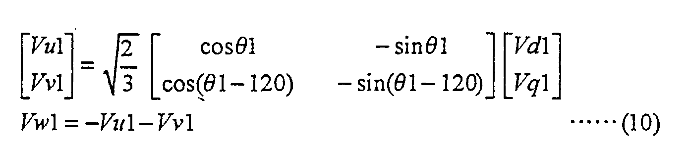
Claims (5)
- A power output apparatus (110) for outputting power to a drive shaft (112), said power output apparatus (110) comprising:characterized in thatan engine (150) having an output shaft (156);a motor (MG1) having a rotating shaft (125), said motor (MG1) inputting and outputting power to and from said rotating shaft (125);three shaft-type power input/output means (120) having three shafts respectively linked with said drive shaft (112), said output shaft (156), and said rotating shaft (125), when powers are input to and output from any two shafts among said three shafts, said power input/output means (120) inputting and outputting power which is determined according to the input and output powers to and from a residual one shaft; andpower control means driving and controlling said motor (MG1) in order to enable the power output from said engine (150) to be subjected to torque conversion by said three shaft-type power input/output means (120) and said motor (MG1) and to be output to said drive shaft (112);
said power control means controls said motor (MG1) so as to be kept in a lock-up state to prevent rotation of said rotating shaft (125), in response to a predetermined driving requirement. - A power output apparatus (110) in accordance with claim 1, further comprising:target power setting means setting a target power to be output to said drive shaft (112);engine power setting means setting a power to be output from said engine (150), based on the target power set by said target power setting means; andengine operation control means controlling operation of said engine (150), based on the power set by said engine power setting means.
- A power output apparatus (110) in accordance with claim 2, wherein said motor (MG1) is a first motor,
said power output apparatus (110) further comprising:a second motor (MG2) for inputting and outputting power to and from said drive shaft (112);storage battery means (94) being charged with electric power regenerated by said second motor (MG2) and being discharged to supply electric power required for driving said second motor (MG2);drive shaft speed measuring means measuring a revolving speed of said drive shaft (112);said engine operation control means controls operation of said engine (150), based on the revolving speed of said drive shaft (112) measured by said drive shaft speed measuring means and the target power set by said target power setting means; andmotor control means driving and controlling said second motor (MG2), in order to enable the target power to be output to said drive shaft (112) by utilizing power output from said engine (150) and power input to and output from said second motor (MG2). - A power output apparatus (110) in accordance with claim 2, wherein said motor (MG1) is a first motor,
said power output apparatus further comprising:a second motor (MG2) for inputting and outputting power to and from said output shaft (156) of said engine (150);storage battery means (94) being discharged to supply electric power to said first motor (MG1) and said second motor (MG2);drive shaft speed measuring means measuring a revolving speed of said drive shaft (112);said engine operation control means controls operation of said engine (150), based on the revolving speed of said drive shaft (112) measured by said drive shaft (112) speed measuring means and the target power set by said target power setting means; andmotor control means driving and controlling said second motor (MG2), in order to enable the target power to be output to said drive shaft (112) by utilizing power output from said engine (150) and power input to and output from said second motor (MG2). - A power output apparatus (110) in accordance with one of claims 1 to 4, wherein
said engine operation control means controls said engine (150) to operate at a driving point that allows the engine (150) to attain the target power, with said driving point of said engine (150) varying with a variation in the amount of the target power.
Applications Claiming Priority (3)
| Application Number | Priority Date | Filing Date | Title |
|---|---|---|---|
| JP14867796 | 1996-05-20 | ||
| JP14867796A JP3050125B2 (en) | 1996-05-20 | 1996-05-20 | Power output device and control method of power output device |
| EP97104645A EP0838359B1 (en) | 1996-05-20 | 1997-03-18 | Power output apparatus and method of controlling the same |
Related Parent Applications (2)
| Application Number | Title | Priority Date | Filing Date |
|---|---|---|---|
| EP97104645.3 Division | 1997-03-18 | ||
| EP97104645A Division EP0838359B1 (en) | 1996-05-20 | 1997-03-18 | Power output apparatus and method of controlling the same |
Publications (3)
| Publication Number | Publication Date |
|---|---|
| EP1106412A2 true EP1106412A2 (en) | 2001-06-13 |
| EP1106412A3 EP1106412A3 (en) | 2005-12-14 |
| EP1106412B1 EP1106412B1 (en) | 2007-04-25 |
Family
ID=15458150
Family Applications (2)
| Application Number | Title | Priority Date | Filing Date |
|---|---|---|---|
| EP97104645A Expired - Lifetime EP0838359B1 (en) | 1996-05-20 | 1997-03-18 | Power output apparatus and method of controlling the same |
| EP01108622A Expired - Lifetime EP1106412B1 (en) | 1996-05-20 | 1997-03-18 | Hybrid power output apparatus for controlling motor / generator to lock planetary gearing elements |
Family Applications Before (1)
| Application Number | Title | Priority Date | Filing Date |
|---|---|---|---|
| EP97104645A Expired - Lifetime EP0838359B1 (en) | 1996-05-20 | 1997-03-18 | Power output apparatus and method of controlling the same |
Country Status (5)
| Country | Link |
|---|---|
| US (1) | US6131680A (en) |
| EP (2) | EP0838359B1 (en) |
| JP (1) | JP3050125B2 (en) |
| KR (1) | KR100254308B1 (en) |
| DE (2) | DE69737662T2 (en) |
Cited By (4)
| Publication number | Priority date | Publication date | Assignee | Title |
|---|---|---|---|---|
| WO2002070298A1 (en) * | 2001-03-06 | 2002-09-12 | Nissan Motor Co.,Ltd. | Hybrid vehicle control system and control method |
| FR2839023A1 (en) * | 2002-04-29 | 2003-10-31 | Renault Sa | Hybrid motor and propulsion unit for motor vehicle, uses epicyclic gear train to couple engine and electric motor to drive wheels, using a gear brake to select which is driving the vehicle |
| EP1279543A3 (en) * | 2001-07-23 | 2003-12-17 | Nissan Motor Co., Ltd. | Hybrid drivetrain for a vehicle |
| WO2006111434A1 (en) * | 2005-04-21 | 2006-10-26 | Robert Bosch Gmbh | Method for operating a hybrid vehicle drive and a device for carrying out said method |
Families Citing this family (66)
| Publication number | Priority date | Publication date | Assignee | Title |
|---|---|---|---|---|
| JP3050141B2 (en) * | 1996-09-24 | 2000-06-12 | トヨタ自動車株式会社 | Power output device and control method thereof |
| US6554088B2 (en) | 1998-09-14 | 2003-04-29 | Paice Corporation | Hybrid vehicles |
| JP3903625B2 (en) * | 1998-12-21 | 2007-04-11 | トヨタ自動車株式会社 | Power output device |
| US6522024B1 (en) | 1998-12-24 | 2003-02-18 | Toyota Jidosha Kabushiki Kaisha | Output state detector for internal combustion engine |
| JP3402236B2 (en) | 1999-01-13 | 2003-05-06 | トヨタ自動車株式会社 | Power output device, hybrid vehicle, and control method therefor |
| JP2000224714A (en) * | 1999-02-03 | 2000-08-11 | Mitsubishi Motors Corp | Vehicle with electric motor |
| US6493618B2 (en) | 2000-03-15 | 2002-12-10 | Toyota Jidosha Kabushiki Kaisha | Vehicle control using multiple sensors |
| JP3624821B2 (en) * | 2000-11-22 | 2005-03-02 | 日産自動車株式会社 | Vehicle control device |
| FR2833888B1 (en) * | 2001-12-20 | 2004-03-19 | Renault | METHOD FOR CONTROLLING A HYBRID DRIVE SYSTEM AND ASSOCIATED DRIVE SYSTEM |
| DE10203064A1 (en) * | 2002-01-28 | 2003-08-07 | Bosch Gmbh Robert | Method for setting an operating point of a hybrid drive of a vehicle |
| US6825644B2 (en) * | 2002-11-14 | 2004-11-30 | Fyre Storm, Inc. | Switching power converter |
| DE10304610A1 (en) * | 2003-02-05 | 2004-08-26 | Robert Bosch Gmbh | Arrangement and method for converting mechanical to electrical energy and vice versa |
| JP2004248382A (en) * | 2003-02-12 | 2004-09-02 | Mitsubishi Motors Corp | Hybrid vehicle |
| DE102004012767A1 (en) | 2004-03-15 | 2005-10-20 | Deere & Co | Drive system for a vehicle |
| JP4479458B2 (en) | 2004-10-19 | 2010-06-09 | トヨタ自動車株式会社 | Vehicle and control method thereof |
| JP4301224B2 (en) * | 2005-02-16 | 2009-07-22 | トヨタ自動車株式会社 | Automobile and control method thereof |
| JP4529726B2 (en) * | 2005-02-23 | 2010-08-25 | トヨタ自動車株式会社 | POWER OUTPUT DEVICE, CONTROL METHOD FOR POWER OUTPUT DEVICE, AND VEHICLE WITH THE SAME |
| US7617893B2 (en) * | 2005-08-02 | 2009-11-17 | Ford Global Technologies, Llc | Method and system for determining final desired wheel power in a hybrid electric vehicle powertrain |
| ITMO20050209A1 (en) * | 2005-08-05 | 2007-02-06 | Giorgio Bordini | HYBRID TRACTION SYSTEM |
| JP4337797B2 (en) * | 2005-09-29 | 2009-09-30 | トヨタ自動車株式会社 | Power control device and electric vehicle |
| US20070169086A1 (en) * | 2005-12-30 | 2007-07-19 | Siliconmotion Inc. | System and method for updating in-system program |
| JP4297913B2 (en) | 2006-02-16 | 2009-07-15 | トヨタ自動車株式会社 | POWER OUTPUT DEVICE, ITS CONTROL METHOD, AND VEHICLE |
| JP4232785B2 (en) * | 2006-02-23 | 2009-03-04 | トヨタ自動車株式会社 | Hybrid vehicle |
| WO2008033378A1 (en) * | 2006-09-12 | 2008-03-20 | Purdue Research Foundation | Power split transmission with energy recovery |
| JP4140647B2 (en) * | 2006-10-24 | 2008-08-27 | トヨタ自動車株式会社 | Power output device and hybrid vehicle |
| JP4297951B2 (en) * | 2007-05-25 | 2009-07-15 | トヨタ自動車株式会社 | Vehicle drive system |
| JP4527138B2 (en) * | 2007-07-12 | 2010-08-18 | 本田技研工業株式会社 | Control device for hybrid vehicle |
| US8172242B1 (en) * | 2008-03-06 | 2012-05-08 | Thomas Crandall | Medical imaging workstation |
| US8955625B2 (en) * | 2009-09-11 | 2015-02-17 | ALTe Technologies, Inc. | Stackable motor |
| WO2012064617A1 (en) | 2010-11-09 | 2012-05-18 | Aram Novikov | Multi-core electric machines |
| JPWO2012090263A1 (en) * | 2010-12-27 | 2014-06-05 | トヨタ自動車株式会社 | Hybrid vehicle |
| US20140046527A1 (en) * | 2011-01-31 | 2014-02-13 | Yoshiki Ito | Drive control apparatus for hybrid vehicle |
| CN103380043B (en) | 2011-02-21 | 2015-12-16 | 铃木株式会社 | The driving control device of motor vehicle driven by mixed power |
| JP5765597B2 (en) | 2011-02-21 | 2015-08-19 | スズキ株式会社 | Drive control apparatus for hybrid vehicle |
| JP5218800B2 (en) | 2011-10-31 | 2013-06-26 | トヨタ自動車株式会社 | VEHICLE HAVING POWER STORAGE UNIT AND CHARGE / DISCHARGE SYSTEM INCLUDING THE VEHICLE AND ENERGY MANAGEMENT |
| JP5234159B2 (en) | 2011-10-31 | 2013-07-10 | トヨタ自動車株式会社 | A vehicle including a power storage unit capable of discharging (power feeding) to an external load, a discharge system including the vehicle and a power cable, a discharge control method for the power storage unit, and a device outside the vehicle used in the discharge system. |
| JP5897885B2 (en) | 2011-11-25 | 2016-04-06 | トヨタ自動車株式会社 | Hybrid vehicle |
| WO2013080376A1 (en) | 2011-12-02 | 2013-06-06 | トヨタ自動車株式会社 | Hybrid vehicle |
| CN104010901B (en) | 2011-12-28 | 2016-11-02 | 丰田自动车株式会社 | Motor vehicle driven by mixed power |
| JP5862296B2 (en) | 2011-12-28 | 2016-02-16 | トヨタ自動車株式会社 | Hybrid vehicle |
| JP5862311B2 (en) * | 2012-01-11 | 2016-02-16 | トヨタ自動車株式会社 | Hybrid vehicle |
| JP5834965B2 (en) * | 2012-01-27 | 2015-12-24 | トヨタ自動車株式会社 | Hybrid vehicle operation status display device |
| JP2013154719A (en) * | 2012-01-27 | 2013-08-15 | Toyota Motor Corp | Electricity cost calculation device of hybrid vehicle |
| JP5682581B2 (en) | 2012-02-28 | 2015-03-11 | トヨタ自動車株式会社 | Hybrid vehicle |
| EP2837537A4 (en) | 2012-04-11 | 2016-07-27 | Toyota Motor Co Ltd | Vehicle control device |
| JP5704109B2 (en) | 2012-04-13 | 2015-04-22 | トヨタ自動車株式会社 | Hybrid vehicle |
| JP5895897B2 (en) | 2013-04-23 | 2016-03-30 | トヨタ自動車株式会社 | Control device for hybrid vehicle |
| JP5939197B2 (en) * | 2013-04-26 | 2016-06-22 | トヨタ自動車株式会社 | Control device for hybrid vehicle |
| JP6217565B2 (en) | 2014-09-05 | 2017-10-25 | トヨタ自動車株式会社 | Vehicle control device |
| JP6492932B2 (en) * | 2015-04-24 | 2019-04-03 | スズキ株式会社 | Control device for hybrid vehicle |
| JP6458667B2 (en) * | 2015-07-01 | 2019-01-30 | スズキ株式会社 | Drive control apparatus for hybrid vehicle |
| JP6369411B2 (en) | 2015-07-22 | 2018-08-08 | トヨタ自動車株式会社 | Control device for hybrid vehicle |
| JP6269607B2 (en) | 2015-07-22 | 2018-01-31 | トヨタ自動車株式会社 | Control device for hybrid vehicle |
| JP6347235B2 (en) | 2015-07-30 | 2018-06-27 | トヨタ自動車株式会社 | Control device for hybrid vehicle |
| JP6304165B2 (en) | 2015-07-31 | 2018-04-04 | トヨタ自動車株式会社 | Control device for hybrid vehicle |
| JP6269641B2 (en) | 2015-11-19 | 2018-01-31 | トヨタ自動車株式会社 | Control device for hybrid vehicle |
| JP6344429B2 (en) | 2016-06-09 | 2018-06-20 | トヨタ自動車株式会社 | Control device for hybrid vehicle |
| WO2018038261A1 (en) | 2016-08-25 | 2018-03-01 | 株式会社 東芝 | Vehicle system |
| JP6800659B2 (en) | 2016-08-25 | 2020-12-16 | 株式会社東芝 | Hybrid vehicle system |
| KR20180067262A (en) * | 2016-12-12 | 2018-06-20 | 현대자동차주식회사 | Apparatus and method for controlling driving of hybrid vehicle |
| JP2018115573A (en) | 2017-01-17 | 2018-07-26 | トヨタ自動車株式会社 | Controller of internal combustion engine |
| JP6617750B2 (en) | 2017-05-23 | 2019-12-11 | トヨタ自動車株式会社 | Control device for vehicle drive device |
| JP7238699B2 (en) * | 2019-08-29 | 2023-03-14 | トヨタ自動車株式会社 | hybrid vehicle |
| JP7207237B2 (en) | 2019-08-29 | 2023-01-18 | トヨタ自動車株式会社 | hybrid vehicle |
| DE102021202472A1 (en) * | 2021-03-15 | 2022-09-15 | Zf Friedrichshafen Ag | Electric gear for two electric drive machines |
| IT202100013190A1 (en) * | 2021-05-20 | 2022-11-20 | Edrivelab S R L | RANGE EXTENDER GENERATOR, VESSEL INCLUDING SUCH GENERATOR AND METHOD OF CONTROLLING A RANGE EXTENDER GENERATOR TO POWER AT LEAST ONE CONSUMPTION OF A VESSEL |
Citations (1)
| Publication number | Priority date | Publication date | Assignee | Title |
|---|---|---|---|---|
| JPH0530223A (en) | 1991-03-29 | 1993-02-05 | Toshiba Corp | Relay exchange |
Family Cites Families (20)
| Publication number | Priority date | Publication date | Assignee | Title |
|---|---|---|---|---|
| GB1193965A (en) * | 1966-06-14 | 1970-06-03 | Nat Res Dev | Torque Converter |
| US3623568A (en) * | 1968-05-31 | 1971-11-30 | Nissan Motor | Electromechanical power train system for an automotive vehicle |
| US3620323A (en) * | 1968-05-31 | 1971-11-16 | Nissan Motor | Electromechanical power train system for an automotive vehicle |
| US3566717A (en) * | 1969-03-17 | 1971-03-02 | Trw Inc | Power train using multiple power sources |
| US3699351A (en) * | 1971-08-02 | 1972-10-17 | Gen Motors Corp | Bi-modal vehicles with drive means for external or self-propulsion |
| AU5840173A (en) * | 1972-07-25 | 1975-01-30 | Stephen John Elliott | Dual mode propulsion system |
| JPS5030223A (en) * | 1973-07-20 | 1975-03-26 | ||
| US5103923A (en) * | 1989-11-30 | 1992-04-14 | Marathon Letourneau Company | Method and apparatus for propelling and retarding off-road haulers |
| ATA6192A (en) * | 1992-01-16 | 1997-05-15 | Avl Verbrennungskraft Messtech | DRIVE DEVICE DRIVE DEVICE |
| JPH05229351A (en) * | 1992-02-19 | 1993-09-07 | Aisin Aw Co Ltd | Motor-driven device for vehicle |
| JP2967103B2 (en) * | 1993-05-24 | 1999-10-25 | 株式会社エクォス・リサーチ | Hybrid vehicle |
| JP3291871B2 (en) * | 1993-11-10 | 2002-06-17 | 株式会社エクォス・リサーチ | Hybrid vehicle |
| JP3291916B2 (en) * | 1994-06-06 | 2002-06-17 | 株式会社エクォス・リサーチ | Hybrid vehicle |
| JP3344848B2 (en) * | 1994-11-04 | 2002-11-18 | アイシン・エィ・ダブリュ株式会社 | Launching device |
| US5823280A (en) * | 1995-01-12 | 1998-10-20 | Nevcor, Inc. | Hybrid parallel electric vehicle |
| JP3173319B2 (en) * | 1995-04-28 | 2001-06-04 | 株式会社エクォス・リサーチ | Hybrid vehicle |
| DE29624299U1 (en) * | 1995-05-19 | 2001-11-22 | Toyota Motor Co Ltd | Power transmission device, and vehicle with four-wheel drive with such a power transmission device |
| JPH0937410A (en) * | 1995-07-24 | 1997-02-07 | Toyota Motor Corp | Drive controller for car |
| US5788640A (en) * | 1995-10-26 | 1998-08-04 | Peters; Robert Mitchell | System and method for performing fuzzy cluster classification of stress tests |
| JPH09277847A (en) * | 1996-04-11 | 1997-10-28 | Toyota Motor Corp | Engine brake control device for hybrid vehicle |
-
1996
- 1996-05-20 JP JP14867796A patent/JP3050125B2/en not_active Expired - Lifetime
-
1997
- 1997-02-03 KR KR1019970003263A patent/KR100254308B1/en not_active IP Right Cessation
- 1997-03-10 US US08/813,404 patent/US6131680A/en not_active Expired - Lifetime
- 1997-03-18 EP EP97104645A patent/EP0838359B1/en not_active Expired - Lifetime
- 1997-03-18 EP EP01108622A patent/EP1106412B1/en not_active Expired - Lifetime
- 1997-03-18 DE DE69737662T patent/DE69737662T2/en not_active Expired - Lifetime
- 1997-03-18 DE DE69716853T patent/DE69716853T2/en not_active Expired - Lifetime
Patent Citations (1)
| Publication number | Priority date | Publication date | Assignee | Title |
|---|---|---|---|---|
| JPH0530223A (en) | 1991-03-29 | 1993-02-05 | Toshiba Corp | Relay exchange |
Cited By (7)
| Publication number | Priority date | Publication date | Assignee | Title |
|---|---|---|---|---|
| WO2002070298A1 (en) * | 2001-03-06 | 2002-09-12 | Nissan Motor Co.,Ltd. | Hybrid vehicle control system and control method |
| US6891279B2 (en) | 2001-03-06 | 2005-05-10 | Nissan Motor Co., Ltd. | Vehicle control system and control method |
| EP1279543A3 (en) * | 2001-07-23 | 2003-12-17 | Nissan Motor Co., Ltd. | Hybrid drivetrain for a vehicle |
| US7004868B2 (en) | 2001-07-23 | 2006-02-28 | Nissan Motor Co., Ltd. | Drivetrain for a vehicle |
| FR2839023A1 (en) * | 2002-04-29 | 2003-10-31 | Renault Sa | Hybrid motor and propulsion unit for motor vehicle, uses epicyclic gear train to couple engine and electric motor to drive wheels, using a gear brake to select which is driving the vehicle |
| WO2006111434A1 (en) * | 2005-04-21 | 2006-10-26 | Robert Bosch Gmbh | Method for operating a hybrid vehicle drive and a device for carrying out said method |
| US8374771B2 (en) | 2005-04-21 | 2013-02-12 | Robert Bosch Gmbh | Method for operating a hybrid vehicle drive and a device for carrying out said method |
Also Published As
| Publication number | Publication date |
|---|---|
| DE69716853D1 (en) | 2002-12-12 |
| EP1106412B1 (en) | 2007-04-25 |
| EP0838359A2 (en) | 1998-04-29 |
| EP0838359A3 (en) | 1999-10-20 |
| DE69716853T2 (en) | 2003-07-10 |
| EP1106412A3 (en) | 2005-12-14 |
| US6131680A (en) | 2000-10-17 |
| DE69737662D1 (en) | 2007-06-06 |
| KR100254308B1 (en) | 2000-05-01 |
| EP0838359B1 (en) | 2002-11-06 |
| JP3050125B2 (en) | 2000-06-12 |
| JPH09308012A (en) | 1997-11-28 |
| KR970074194A (en) | 1997-12-10 |
| DE69737662T2 (en) | 2008-01-31 |
Similar Documents
| Publication | Publication Date | Title |
|---|---|---|
| EP0838359B1 (en) | Power output apparatus and method of controlling the same | |
| EP0830969B1 (en) | Power output apparatus and method of controlling the same | |
| JP3610687B2 (en) | Start control device for internal combustion engine and control method thereof | |
| US5914575A (en) | Power output apparatus and method of controlling the same | |
| EP0868005B1 (en) | Power output apparatus and method of controlling the same | |
| EP0829387B1 (en) | Power output apparatus and method of controlling the same | |
| US5991683A (en) | Power output apparatus and method of controlling the same | |
| US5988307A (en) | Power transmission apparatus, four-wheel drive vehicle with power transmission apparatus incorporated therein, method of transmitting power, and method of four-wheel driving | |
| EP0861163B1 (en) | Power output apparatus, method of controlling power output apparatus, and driving system with power output apparatus incorporated therein | |
| EP0775607B1 (en) | Hybrid transmission system, four-wheel drive vehicle using the same, power transmitting method, and four-wheel driving method | |
| US6166499A (en) | Power output apparatus and method of regulating power | |
| US5998901A (en) | Power output apparatus | |
| JP3921901B2 (en) | POWER OUTPUT DEVICE AND POWER OUTPUT METHOD | |
| EP0743212B1 (en) | Hybrid vehicle power output apparatus and method of controlling the same | |
| JP3161328B2 (en) | Power transmission device, four-wheel drive vehicle using the same, power transmission method and four-wheel drive method | |
| JP3191705B2 (en) | Drive unit and power output unit | |
| EP0743217A2 (en) | Hybrid vehicle power output apparatus and method of controlling the same during engine braking |
Legal Events
| Date | Code | Title | Description |
|---|---|---|---|
| PUAI | Public reference made under article 153(3) epc to a published international application that has entered the european phase |
Free format text: ORIGINAL CODE: 0009012 |
|
| 17P | Request for examination filed |
Effective date: 20010405 |
|
| AC | Divisional application: reference to earlier application |
Ref document number: 838359 Country of ref document: EP |
|
| AK | Designated contracting states |
Kind code of ref document: A2 Designated state(s): DE FR GB |
|
| PUAL | Search report despatched |
Free format text: ORIGINAL CODE: 0009013 |
|
| AK | Designated contracting states |
Kind code of ref document: A3 Designated state(s): DE FR GB |
|
| RIC1 | Information provided on ipc code assigned before grant |
Ipc: 7B 60K 41/00 B Ipc: 7B 60L 11/12 B Ipc: 7B 60K 6/04 A |
|
| AKX | Designation fees paid |
Designated state(s): DE FR GB |
|
| GRAP | Despatch of communication of intention to grant a patent |
Free format text: ORIGINAL CODE: EPIDOSNIGR1 |
|
| RTI1 | Title (correction) |
Free format text: HYBRID POWER OUTPUT APPARATUS FOR CONTROLLING MOTOR / GENERATOR TO LOCK PLANETARY GEARING ELEMENTS |
|
| RIC1 | Information provided on ipc code assigned before grant |
Ipc: B60W 20/00 20060101AFI20060928BHEP Ipc: B60K 6/04 20060101ALI20060928BHEP Ipc: B60L 11/12 20060101ALI20060928BHEP |
|
| GRAS | Grant fee paid |
Free format text: ORIGINAL CODE: EPIDOSNIGR3 |
|
| RIN1 | Information on inventor provided before grant (corrected) |
Inventor name: KOTANI, TAKESHI Inventor name: NII, YOSHIHIDE Inventor name: SASAKI, SHOICHI |
|
| GRAA | (expected) grant |
Free format text: ORIGINAL CODE: 0009210 |
|
| AC | Divisional application: reference to earlier application |
Ref document number: 0838359 Country of ref document: EP Kind code of ref document: P |
|
| AK | Designated contracting states |
Kind code of ref document: B1 Designated state(s): DE FR GB |
|
| REG | Reference to a national code |
Ref country code: GB Ref legal event code: FG4D |
|
| REF | Corresponds to: |
Ref document number: 69737662 Country of ref document: DE Date of ref document: 20070606 Kind code of ref document: P |
|
| ET | Fr: translation filed | ||
| PLBE | No opposition filed within time limit |
Free format text: ORIGINAL CODE: 0009261 |
|
| STAA | Information on the status of an ep patent application or granted ep patent |
Free format text: STATUS: NO OPPOSITION FILED WITHIN TIME LIMIT |
|
| 26N | No opposition filed |
Effective date: 20080128 |
|
| REG | Reference to a national code |
Ref country code: GB Ref legal event code: 746 Effective date: 20121221 |
|
| REG | Reference to a national code |
Ref country code: DE Ref legal event code: R084 Ref document number: 69737662 Country of ref document: DE Effective date: 20121219 |
|
| REG | Reference to a national code |
Ref country code: FR Ref legal event code: PLFP Year of fee payment: 20 |
|
| PGFP | Annual fee paid to national office [announced via postgrant information from national office to epo] |
Ref country code: DE Payment date: 20160315 Year of fee payment: 20 |
|
| PGFP | Annual fee paid to national office [announced via postgrant information from national office to epo] |
Ref country code: GB Payment date: 20160316 Year of fee payment: 20 Ref country code: FR Payment date: 20160208 Year of fee payment: 20 |
|
| REG | Reference to a national code |
Ref country code: DE Ref legal event code: R071 Ref document number: 69737662 Country of ref document: DE |
|
| REG | Reference to a national code |
Ref country code: GB Ref legal event code: PE20 Expiry date: 20170317 |
|
| PG25 | Lapsed in a contracting state [announced via postgrant information from national office to epo] |
Ref country code: GB Free format text: LAPSE BECAUSE OF EXPIRATION OF PROTECTION Effective date: 20170317 |