EP1105930B1 - Laser cutting and joining a fluorinated polymer membrane to a polymer frame - Google Patents
Laser cutting and joining a fluorinated polymer membrane to a polymer frame Download PDFInfo
- Publication number
- EP1105930B1 EP1105930B1 EP99934890A EP99934890A EP1105930B1 EP 1105930 B1 EP1105930 B1 EP 1105930B1 EP 99934890 A EP99934890 A EP 99934890A EP 99934890 A EP99934890 A EP 99934890A EP 1105930 B1 EP1105930 B1 EP 1105930B1
- Authority
- EP
- European Patent Office
- Prior art keywords
- membrane
- copolymer
- frame
- fluorinated polymer
- laser beam
- Prior art date
- Legal status (The legal status is an assumption and is not a legal conclusion. Google has not performed a legal analysis and makes no representation as to the accuracy of the status listed.)
- Expired - Lifetime
Links
Images
Classifications
-
- H—ELECTRICITY
- H01—ELECTRIC ELEMENTS
- H01M—PROCESSES OR MEANS, e.g. BATTERIES, FOR THE DIRECT CONVERSION OF CHEMICAL ENERGY INTO ELECTRICAL ENERGY
- H01M8/00—Fuel cells; Manufacture thereof
- H01M8/02—Details
-
- B—PERFORMING OPERATIONS; TRANSPORTING
- B29—WORKING OF PLASTICS; WORKING OF SUBSTANCES IN A PLASTIC STATE IN GENERAL
- B29C—SHAPING OR JOINING OF PLASTICS; SHAPING OF MATERIAL IN A PLASTIC STATE, NOT OTHERWISE PROVIDED FOR; AFTER-TREATMENT OF THE SHAPED PRODUCTS, e.g. REPAIRING
- B29C66/00—General aspects of processes or apparatus for joining preformed parts
- B29C66/80—General aspects of machine operations or constructions and parts thereof
- B29C66/82—Pressure application arrangements, e.g. transmission or actuating mechanisms for joining tools or clamps
- B29C66/826—Pressure application arrangements, e.g. transmission or actuating mechanisms for joining tools or clamps without using a separate pressure application tool, e.g. the own weight of the parts to be joined
- B29C66/8266—Pressure application arrangements, e.g. transmission or actuating mechanisms for joining tools or clamps without using a separate pressure application tool, e.g. the own weight of the parts to be joined using fluid pressure directly acting on the parts to be joined
- B29C66/82661—Pressure application arrangements, e.g. transmission or actuating mechanisms for joining tools or clamps without using a separate pressure application tool, e.g. the own weight of the parts to be joined using fluid pressure directly acting on the parts to be joined by means of vacuum
-
- B—PERFORMING OPERATIONS; TRANSPORTING
- B29—WORKING OF PLASTICS; WORKING OF SUBSTANCES IN A PLASTIC STATE IN GENERAL
- B29C—SHAPING OR JOINING OF PLASTICS; SHAPING OF MATERIAL IN A PLASTIC STATE, NOT OTHERWISE PROVIDED FOR; AFTER-TREATMENT OF THE SHAPED PRODUCTS, e.g. REPAIRING
- B29C65/00—Joining or sealing of preformed parts, e.g. welding of plastics materials; Apparatus therefor
-
- B—PERFORMING OPERATIONS; TRANSPORTING
- B29—WORKING OF PLASTICS; WORKING OF SUBSTANCES IN A PLASTIC STATE IN GENERAL
- B29C—SHAPING OR JOINING OF PLASTICS; SHAPING OF MATERIAL IN A PLASTIC STATE, NOT OTHERWISE PROVIDED FOR; AFTER-TREATMENT OF THE SHAPED PRODUCTS, e.g. REPAIRING
- B29C65/00—Joining or sealing of preformed parts, e.g. welding of plastics materials; Apparatus therefor
- B29C65/02—Joining or sealing of preformed parts, e.g. welding of plastics materials; Apparatus therefor by heating, with or without pressure
- B29C65/14—Joining or sealing of preformed parts, e.g. welding of plastics materials; Apparatus therefor by heating, with or without pressure using wave energy, i.e. electromagnetic radiation, or particle radiation
- B29C65/16—Laser beams
-
- B—PERFORMING OPERATIONS; TRANSPORTING
- B29—WORKING OF PLASTICS; WORKING OF SUBSTANCES IN A PLASTIC STATE IN GENERAL
- B29C—SHAPING OR JOINING OF PLASTICS; SHAPING OF MATERIAL IN A PLASTIC STATE, NOT OTHERWISE PROVIDED FOR; AFTER-TREATMENT OF THE SHAPED PRODUCTS, e.g. REPAIRING
- B29C65/00—Joining or sealing of preformed parts, e.g. welding of plastics materials; Apparatus therefor
- B29C65/02—Joining or sealing of preformed parts, e.g. welding of plastics materials; Apparatus therefor by heating, with or without pressure
- B29C65/14—Joining or sealing of preformed parts, e.g. welding of plastics materials; Apparatus therefor by heating, with or without pressure using wave energy, i.e. electromagnetic radiation, or particle radiation
- B29C65/16—Laser beams
- B29C65/1603—Laser beams characterised by the type of electromagnetic radiation
- B29C65/1612—Infrared [IR] radiation, e.g. by infrared lasers
- B29C65/1619—Mid infrared radiation [MIR], e.g. by CO or CO2 lasers
-
- B—PERFORMING OPERATIONS; TRANSPORTING
- B29—WORKING OF PLASTICS; WORKING OF SUBSTANCES IN A PLASTIC STATE IN GENERAL
- B29C—SHAPING OR JOINING OF PLASTICS; SHAPING OF MATERIAL IN A PLASTIC STATE, NOT OTHERWISE PROVIDED FOR; AFTER-TREATMENT OF THE SHAPED PRODUCTS, e.g. REPAIRING
- B29C65/00—Joining or sealing of preformed parts, e.g. welding of plastics materials; Apparatus therefor
- B29C65/74—Joining or sealing of preformed parts, e.g. welding of plastics materials; Apparatus therefor by welding and severing, or by joining and severing, the severing being performed in the area to be joined, next to the area to be joined, in the joint area or next to the joint area
- B29C65/747—Joining or sealing of preformed parts, e.g. welding of plastics materials; Apparatus therefor by welding and severing, or by joining and severing, the severing being performed in the area to be joined, next to the area to be joined, in the joint area or next to the joint area using other than mechanical means
- B29C65/7473—Joining or sealing of preformed parts, e.g. welding of plastics materials; Apparatus therefor by welding and severing, or by joining and severing, the severing being performed in the area to be joined, next to the area to be joined, in the joint area or next to the joint area using other than mechanical means using radiation, e.g. laser, for simultaneously welding and severing
-
- B—PERFORMING OPERATIONS; TRANSPORTING
- B29—WORKING OF PLASTICS; WORKING OF SUBSTANCES IN A PLASTIC STATE IN GENERAL
- B29C—SHAPING OR JOINING OF PLASTICS; SHAPING OF MATERIAL IN A PLASTIC STATE, NOT OTHERWISE PROVIDED FOR; AFTER-TREATMENT OF THE SHAPED PRODUCTS, e.g. REPAIRING
- B29C66/00—General aspects of processes or apparatus for joining preformed parts
- B29C66/002—Removing toxic gases
-
- B—PERFORMING OPERATIONS; TRANSPORTING
- B29—WORKING OF PLASTICS; WORKING OF SUBSTANCES IN A PLASTIC STATE IN GENERAL
- B29C—SHAPING OR JOINING OF PLASTICS; SHAPING OF MATERIAL IN A PLASTIC STATE, NOT OTHERWISE PROVIDED FOR; AFTER-TREATMENT OF THE SHAPED PRODUCTS, e.g. REPAIRING
- B29C66/00—General aspects of processes or apparatus for joining preformed parts
- B29C66/50—General aspects of joining tubular articles; General aspects of joining long products, i.e. bars or profiled elements; General aspects of joining single elements to tubular articles, hollow articles or bars; General aspects of joining several hollow-preforms to form hollow or tubular articles
- B29C66/51—Joining tubular articles, profiled elements or bars; Joining single elements to tubular articles, hollow articles or bars; Joining several hollow-preforms to form hollow or tubular articles
- B29C66/53—Joining single elements to tubular articles, hollow articles or bars
- B29C66/534—Joining single elements to open ends of tubular or hollow articles or to the ends of bars
- B29C66/5346—Joining single elements to open ends of tubular or hollow articles or to the ends of bars said single elements being substantially flat
-
- B—PERFORMING OPERATIONS; TRANSPORTING
- B29—WORKING OF PLASTICS; WORKING OF SUBSTANCES IN A PLASTIC STATE IN GENERAL
- B29C—SHAPING OR JOINING OF PLASTICS; SHAPING OF MATERIAL IN A PLASTIC STATE, NOT OTHERWISE PROVIDED FOR; AFTER-TREATMENT OF THE SHAPED PRODUCTS, e.g. REPAIRING
- B29C66/00—General aspects of processes or apparatus for joining preformed parts
- B29C66/70—General aspects of processes or apparatus for joining preformed parts characterised by the composition, physical properties or the structure of the material of the parts to be joined; Joining with non-plastics material
- B29C66/71—General aspects of processes or apparatus for joining preformed parts characterised by the composition, physical properties or the structure of the material of the parts to be joined; Joining with non-plastics material characterised by the composition of the plastics material of the parts to be joined
-
- B—PERFORMING OPERATIONS; TRANSPORTING
- B29—WORKING OF PLASTICS; WORKING OF SUBSTANCES IN A PLASTIC STATE IN GENERAL
- B29C—SHAPING OR JOINING OF PLASTICS; SHAPING OF MATERIAL IN A PLASTIC STATE, NOT OTHERWISE PROVIDED FOR; AFTER-TREATMENT OF THE SHAPED PRODUCTS, e.g. REPAIRING
- B29C66/00—General aspects of processes or apparatus for joining preformed parts
- B29C66/80—General aspects of machine operations or constructions and parts thereof
- B29C66/82—Pressure application arrangements, e.g. transmission or actuating mechanisms for joining tools or clamps
- B29C66/826—Pressure application arrangements, e.g. transmission or actuating mechanisms for joining tools or clamps without using a separate pressure application tool, e.g. the own weight of the parts to be joined
- B29C66/8266—Pressure application arrangements, e.g. transmission or actuating mechanisms for joining tools or clamps without using a separate pressure application tool, e.g. the own weight of the parts to be joined using fluid pressure directly acting on the parts to be joined
-
- B—PERFORMING OPERATIONS; TRANSPORTING
- B29—WORKING OF PLASTICS; WORKING OF SUBSTANCES IN A PLASTIC STATE IN GENERAL
- B29C—SHAPING OR JOINING OF PLASTICS; SHAPING OF MATERIAL IN A PLASTIC STATE, NOT OTHERWISE PROVIDED FOR; AFTER-TREATMENT OF THE SHAPED PRODUCTS, e.g. REPAIRING
- B29C66/00—General aspects of processes or apparatus for joining preformed parts
- B29C66/90—Measuring or controlling the joining process
- B29C66/91—Measuring or controlling the joining process by measuring or controlling the temperature, the heat or the thermal flux
- B29C66/914—Measuring or controlling the joining process by measuring or controlling the temperature, the heat or the thermal flux by controlling or regulating the temperature, the heat or the thermal flux
- B29C66/9161—Measuring or controlling the joining process by measuring or controlling the temperature, the heat or the thermal flux by controlling or regulating the temperature, the heat or the thermal flux by controlling or regulating the heat or the thermal flux, i.e. the heat flux
-
- B—PERFORMING OPERATIONS; TRANSPORTING
- B29—WORKING OF PLASTICS; WORKING OF SUBSTANCES IN A PLASTIC STATE IN GENERAL
- B29C—SHAPING OR JOINING OF PLASTICS; SHAPING OF MATERIAL IN A PLASTIC STATE, NOT OTHERWISE PROVIDED FOR; AFTER-TREATMENT OF THE SHAPED PRODUCTS, e.g. REPAIRING
- B29C66/00—General aspects of processes or apparatus for joining preformed parts
- B29C66/90—Measuring or controlling the joining process
- B29C66/91—Measuring or controlling the joining process by measuring or controlling the temperature, the heat or the thermal flux
- B29C66/919—Measuring or controlling the joining process by measuring or controlling the temperature, the heat or the thermal flux characterised by specific temperature, heat or thermal flux values or ranges
-
- B—PERFORMING OPERATIONS; TRANSPORTING
- B29—WORKING OF PLASTICS; WORKING OF SUBSTANCES IN A PLASTIC STATE IN GENERAL
- B29C—SHAPING OR JOINING OF PLASTICS; SHAPING OF MATERIAL IN A PLASTIC STATE, NOT OTHERWISE PROVIDED FOR; AFTER-TREATMENT OF THE SHAPED PRODUCTS, e.g. REPAIRING
- B29C66/00—General aspects of processes or apparatus for joining preformed parts
- B29C66/90—Measuring or controlling the joining process
- B29C66/93—Measuring or controlling the joining process by measuring or controlling the speed
- B29C66/934—Measuring or controlling the joining process by measuring or controlling the speed by controlling or regulating the speed
-
- B—PERFORMING OPERATIONS; TRANSPORTING
- B29—WORKING OF PLASTICS; WORKING OF SUBSTANCES IN A PLASTIC STATE IN GENERAL
- B29C—SHAPING OR JOINING OF PLASTICS; SHAPING OF MATERIAL IN A PLASTIC STATE, NOT OTHERWISE PROVIDED FOR; AFTER-TREATMENT OF THE SHAPED PRODUCTS, e.g. REPAIRING
- B29C66/00—General aspects of processes or apparatus for joining preformed parts
- B29C66/90—Measuring or controlling the joining process
- B29C66/93—Measuring or controlling the joining process by measuring or controlling the speed
- B29C66/939—Measuring or controlling the joining process by measuring or controlling the speed characterised by specific speed values or ranges
-
- B—PERFORMING OPERATIONS; TRANSPORTING
- B29—WORKING OF PLASTICS; WORKING OF SUBSTANCES IN A PLASTIC STATE IN GENERAL
- B29C—SHAPING OR JOINING OF PLASTICS; SHAPING OF MATERIAL IN A PLASTIC STATE, NOT OTHERWISE PROVIDED FOR; AFTER-TREATMENT OF THE SHAPED PRODUCTS, e.g. REPAIRING
- B29C65/00—Joining or sealing of preformed parts, e.g. welding of plastics materials; Apparatus therefor
- B29C65/02—Joining or sealing of preformed parts, e.g. welding of plastics materials; Apparatus therefor by heating, with or without pressure
- B29C65/14—Joining or sealing of preformed parts, e.g. welding of plastics materials; Apparatus therefor by heating, with or without pressure using wave energy, i.e. electromagnetic radiation, or particle radiation
- B29C65/16—Laser beams
- B29C65/1629—Laser beams characterised by the way of heating the interface
- B29C65/1664—Laser beams characterised by the way of heating the interface making use of several radiators
-
- B—PERFORMING OPERATIONS; TRANSPORTING
- B29—WORKING OF PLASTICS; WORKING OF SUBSTANCES IN A PLASTIC STATE IN GENERAL
- B29C—SHAPING OR JOINING OF PLASTICS; SHAPING OF MATERIAL IN A PLASTIC STATE, NOT OTHERWISE PROVIDED FOR; AFTER-TREATMENT OF THE SHAPED PRODUCTS, e.g. REPAIRING
- B29C65/00—Joining or sealing of preformed parts, e.g. welding of plastics materials; Apparatus therefor
- B29C65/78—Means for handling the parts to be joined, e.g. for making containers or hollow articles, e.g. means for handling sheets, plates, web-like materials, tubular articles, hollow articles or elements to be joined therewith; Means for discharging the joined articles from the joining apparatus
- B29C65/7841—Holding or clamping means for handling purposes
- B29C65/7847—Holding or clamping means for handling purposes using vacuum to hold at least one of the parts to be joined
-
- B—PERFORMING OPERATIONS; TRANSPORTING
- B29—WORKING OF PLASTICS; WORKING OF SUBSTANCES IN A PLASTIC STATE IN GENERAL
- B29C—SHAPING OR JOINING OF PLASTICS; SHAPING OF MATERIAL IN A PLASTIC STATE, NOT OTHERWISE PROVIDED FOR; AFTER-TREATMENT OF THE SHAPED PRODUCTS, e.g. REPAIRING
- B29C66/00—General aspects of processes or apparatus for joining preformed parts
- B29C66/80—General aspects of machine operations or constructions and parts thereof
-
- B—PERFORMING OPERATIONS; TRANSPORTING
- B29—WORKING OF PLASTICS; WORKING OF SUBSTANCES IN A PLASTIC STATE IN GENERAL
- B29C—SHAPING OR JOINING OF PLASTICS; SHAPING OF MATERIAL IN A PLASTIC STATE, NOT OTHERWISE PROVIDED FOR; AFTER-TREATMENT OF THE SHAPED PRODUCTS, e.g. REPAIRING
- B29C66/00—General aspects of processes or apparatus for joining preformed parts
- B29C66/80—General aspects of machine operations or constructions and parts thereof
- B29C66/84—Specific machine types or machines suitable for specific applications
- B29C66/863—Robotised, e.g. mounted on a robot arm
-
- B—PERFORMING OPERATIONS; TRANSPORTING
- B29—WORKING OF PLASTICS; WORKING OF SUBSTANCES IN A PLASTIC STATE IN GENERAL
- B29K—INDEXING SCHEME ASSOCIATED WITH SUBCLASSES B29B, B29C OR B29D, RELATING TO MOULDING MATERIALS OR TO MATERIALS FOR MOULDS, REINFORCEMENTS, FILLERS OR PREFORMED PARTS, e.g. INSERTS
- B29K2027/00—Use of polyvinylhalogenides or derivatives thereof as moulding material
- B29K2027/12—Use of polyvinylhalogenides or derivatives thereof as moulding material containing fluorine
-
- B—PERFORMING OPERATIONS; TRANSPORTING
- B29—WORKING OF PLASTICS; WORKING OF SUBSTANCES IN A PLASTIC STATE IN GENERAL
- B29K—INDEXING SCHEME ASSOCIATED WITH SUBCLASSES B29B, B29C OR B29D, RELATING TO MOULDING MATERIALS OR TO MATERIALS FOR MOULDS, REINFORCEMENTS, FILLERS OR PREFORMED PARTS, e.g. INSERTS
- B29K2027/00—Use of polyvinylhalogenides or derivatives thereof as moulding material
- B29K2027/12—Use of polyvinylhalogenides or derivatives thereof as moulding material containing fluorine
- B29K2027/18—PTFE, i.e. polytetrafluoroethylene, e.g. ePTFE, i.e. expanded polytetrafluoroethylene
-
- B—PERFORMING OPERATIONS; TRANSPORTING
- B29—WORKING OF PLASTICS; WORKING OF SUBSTANCES IN A PLASTIC STATE IN GENERAL
- B29L—INDEXING SCHEME ASSOCIATED WITH SUBCLASS B29C, RELATING TO PARTICULAR ARTICLES
- B29L2007/00—Flat articles, e.g. films or sheets
- B29L2007/008—Wide strips, e.g. films, webs
-
- B—PERFORMING OPERATIONS; TRANSPORTING
- B29—WORKING OF PLASTICS; WORKING OF SUBSTANCES IN A PLASTIC STATE IN GENERAL
- B29L—INDEXING SCHEME ASSOCIATED WITH SUBCLASS B29C, RELATING TO PARTICULAR ARTICLES
- B29L2012/00—Frames
-
- B—PERFORMING OPERATIONS; TRANSPORTING
- B29—WORKING OF PLASTICS; WORKING OF SUBSTANCES IN A PLASTIC STATE IN GENERAL
- B29L—INDEXING SCHEME ASSOCIATED WITH SUBCLASS B29C, RELATING TO PARTICULAR ARTICLES
- B29L2031/00—Other particular articles
- B29L2031/14—Filters
-
- B—PERFORMING OPERATIONS; TRANSPORTING
- B29—WORKING OF PLASTICS; WORKING OF SUBSTANCES IN A PLASTIC STATE IN GENERAL
- B29L—INDEXING SCHEME ASSOCIATED WITH SUBCLASS B29C, RELATING TO PARTICULAR ARTICLES
- B29L2031/00—Other particular articles
- B29L2031/18—Heat-exchangers or parts thereof
-
- B—PERFORMING OPERATIONS; TRANSPORTING
- B29—WORKING OF PLASTICS; WORKING OF SUBSTANCES IN A PLASTIC STATE IN GENERAL
- B29L—INDEXING SCHEME ASSOCIATED WITH SUBCLASS B29C, RELATING TO PARTICULAR ARTICLES
- B29L2031/00—Other particular articles
- B29L2031/34—Electrical apparatus, e.g. sparking plugs or parts thereof
- B29L2031/3468—Batteries, accumulators or fuel cells
-
- Y—GENERAL TAGGING OF NEW TECHNOLOGICAL DEVELOPMENTS; GENERAL TAGGING OF CROSS-SECTIONAL TECHNOLOGIES SPANNING OVER SEVERAL SECTIONS OF THE IPC; TECHNICAL SUBJECTS COVERED BY FORMER USPC CROSS-REFERENCE ART COLLECTIONS [XRACs] AND DIGESTS
- Y02—TECHNOLOGIES OR APPLICATIONS FOR MITIGATION OR ADAPTATION AGAINST CLIMATE CHANGE
- Y02E—REDUCTION OF GREENHOUSE GAS [GHG] EMISSIONS, RELATED TO ENERGY GENERATION, TRANSMISSION OR DISTRIBUTION
- Y02E60/00—Enabling technologies; Technologies with a potential or indirect contribution to GHG emissions mitigation
- Y02E60/30—Hydrogen technology
- Y02E60/50—Fuel cells
Definitions
- the present invention relates to a method for cutting a fluorinated polymer membrane and simultaneously joining it to a polyolefin polymeric supporting frame.
- a method for cutting a fluorinated polymer membrane and simultaneously joining it to a polyolefin polymeric supporting frame may be useful in processes for the manufacture of filters, heat exchangers and electrochemical devices.
- the supporting frame may further comprise an electrode attached thereto so that the resultant frame/electrode/membrane combination forms a sub-assembly which may then be stacked together with other identical sub-assemblies to form an array of electrochemical cells, each cell thus comprising two bipolar electrodes with a membrane positioned therebetween so as to define separate anolyte-containing and catholyte-containing chambers within each cell.
- Such assemblies are well known to those skilled in the art and they may be used as fuel cells, electrolysers and secondary batteries.
- the membrane must be accurately cut to the correct shape so that it fits the shape of the supporting frame.
- the membrane must be accurately positioned on the supporting frame and its position must be verified as being correct prior to its attachment to the supporting frame. This second requirement becomes especially difficult to achieve as the size of the membrane and frame increases.
- the membranes are often very thin making them difficult to handle.
- the first and second requirements are satisfied simultaneously by cutting the membrane in situ.
- the membrane must be attached to the supporting frame with sufficient strength to allow handling of the complete sub-assembly, for example, during stacking to form an array of electrochemical cells.
- the present invention relates to a method for the attachment of a fluorinated polymer ion-exchange membrane onto a polymeric supporting frame.
- the supporting frame is preferably made of a single polyolefin polymer.
- the sub-assembly is to comprise a fluorinated polymer ion-exchange membrane.
- the chemical and physical properties of these membranes allow chemical species to wick through their thickness to the edges where they may leak out into unwanted areas of the sub-assembly causing both a loss of electrolyte and resultant contamination of the surroundings of the cells.
- the edges of the membrane should preferably be de-functionalised in some way so as to prevent this wicking effect.
- Known methods for cutting the membrane to the required shape include the use of a cutting die formed into the required shape, or the use of cutting knives of various types.
- these methods are often not suitable for simultaneous aligning of the cut membrane on the frame, i.e. in situ cutting. Accordingly they require further handling of the membrane in order to position it prior to attachment to the frame.
- they involve physical contact between cutting edges and the membrane which may result in misalignment of, or damage to, the membrane.
- a number of methods for attaching a fluorinated polymer membrane onto a polymeric frame are known.
- Plastic rivets may be used to create a permanent mechanical attachment to the frame.
- this method suffers from the disadvantages that it involves the extra step of punching holes in the membrane and it also results in local attachment only.
- Glues such as those based on silane compounds may also be used.
- the differing chemical properties of the fluorinated polymer membranes and frame polymers to which the present invention is particularly directed mean that selection of a glue which is compatible with both materials is very difficult.
- the method of the present invention is directed toward the manufacture of sub-assemblies for forming electrochemical cells, it is preferable that the glue selected be chemically stable in the aggressive chemical environments commonly found in such electrochemical cells.
- the present invention provides a method for cutting a fluorinated polymer membrane and simultaneously joining it to a polyolefin polymer frame, the method comprising the steps of;
- the present method allows cutting of the membrane to take place in situ, thus obviating the need for subsequent alignment of the cut membrane on the frame prior to joining. Furthermore, the use of a laser to cut the membrane is surprisingly found to simultaneously effect a join between the edge of the membrane and the frame. The join is found to be of sufficient strength and durability to allow subsequent handling of the membrane/frame sub-assembly.
- fluorinated polymers membranes of which may be cut and simultaneously joined to a polymer using this method, include polytetrafluoroethylene, polyhexafluoropropylene, tetrafluoroethylene-hexafluoropropylene copolymer, tetrafluoroethylene-propylene copolymer, tetrafluoroethylene-ethylene copolymer, hexafluoropropylene-propylene copolymer hexafluoropropylene-ethylene copolymer, polyvinylidene fluoride, vinylidene fluoride tetrafluoroethylene copolymer, vinylidene fluoride hexafluoropropylene copolymer, polyvinyl fluoride, tetrafluoroethylene-perfluoroalkyl vinyl ether copolymer, polyvinylidene-hexafluoropropylene copolymer, chlorotrifluoroethylene-ethylene copo
- the fluorinated polymer membrane is a fluorinated polymer ion-exchange membrane and even more preferably the fluorinated polymer membrane is a fluorinated polymer cation-exchange membrane.
- Fluorinated polymer ion-exchange membranes may be formed from any of the fluorinated polymers described above with suitably functionalised monomer units grafted thereon.
- Suitably functionalised monomer units are well known to those skilled in the art and their structures are variable, however they essentially comprise an unsaturated functional group such as a vinyl group and an ion-exchange group such as a sulfonate or carboxylate group.
- the membrane is a hydrolysed copolymer of tetrafluoroethylene and a perfluoro-vinyl ether monomer comprising a cation-exchange group.
- preferred cation exchange membranes include copolymers of tetrafluoroethylene and a sulfonated or carboxylated perfluoro-vinyl ether such as those sold under the trade names of NafionTM (Du Pont), FlemionTM (Asahi Glass)and AciplexTM (Asahi Chemical).
- the thickness of the membrane is in the range of from 25 ⁇ m to 300 ⁇ m, more preferably from 30 ⁇ m to 200 ⁇ m, even more preferably from 50 ⁇ m to 150 ⁇ m.
- the membrane to be attached to the frame may also comprise an electrode attached thereto.
- Such membrane/electrode assemblies are well known in the art and all references to a membrane in this specification are intended to include such assemblies.
- the polyolefin polymeric frame may be formed from a wide range of polymers or copolymers. Suitable polymers include those selected from polyethylene, polypropylene, polystyrene and copolymer blends of two or more of polyethylene, polypropylene and polystyrene, and many others.
- the selection of a hydrogenated polymer frame material is particularly advantageous. This is because pyrolysis of perfluorinated polymers carries with it the possibility of the formation of perfluorisobutene (PFIB) which is highly toxic. Co-pyrolysis with hydrogenated material is found to produce little or no PFIB. It is believed that this is due to the rapid addition of hydrogen radicals to fluorocarbon radical intermediates formed by fluorocarbon degradation, thus preventing recombination of fluorocarbon radicals to yield PFIB.
- PFIB perfluorisobutene
- the present method not only cuts the membrane and simultaneously joins it to the frame but surprisingly is also found to effect de-functionalisation of the cut edge of the membrane.
- de-functionalisation is intended to mean that the nature of the ion exchange membrane is altered in some way so that it no longer exhibits the same characteristics. In particular, it means that chemical species are no longer able to wick through the thickness of the membrane.
- the de-functionalisation of the membrane can be confirmed by staining the membrane with methylene blue which is a cationic dye. The de-functionalised region is not stained by the dye whilst the unaffected region is stained a deep blue colour. Thus, the problem of wicking associated with the use of such membranes is also addressed by the method of the present invention.
- the laser source may be selected from a number of different types of laser and that the laser beam may be either pulsed or continuous.
- the laser used is a pulsed CO 2 laser because the wavelength of light generated by this laser is particularly suitable for cutting the preferred polymer membranes mentioned above.
- the power of the laser beam to be used and the cutting speed achievable are interrelated and also dependent upon other parameters, in particular, upon the chemical structure and the thickness of the membrane.
- the power of the laser beam is preferably in the range of from 10W to 150W and the cutting speed is preferably in the range of from 10mm/s to 1000mm/s, more preferably from 20mm/s to 500mm/s, even more preferably from 50mm/s to 200mm/s and most preferably from 100mm/s to 200mm/s.
- the focus of the laser beam may also be varied, depending upon the other set-up parameters, so as to provide a broader or narrower width of irradiation of the membrane along the line of the cut/join.
- the width of the beam as it impinges on the membrane is in the range of from 50 ⁇ m to 450 ⁇ m, more preferably from 250 ⁇ m to 400 ⁇ m.
- a narrower, i.e. more focussed, beam will provide a faster cutting speed but a weaker join whilst a wider, i.e. more diffuse, beam will provide a stronger join but at a slower cutting speed.
- a wider beam also aids the physical separation of the functional membrane from the scrap membrane.
- a narrow beam allows a faster cutting speed but ease of physical separation of the functional membrane from the scrap membrane is sacrificed.
- the present invention is not necessarily limited to the use of a single laser beam and it will be appreciated by those skilled in the art that other beam arrangements such as a dual beam or concentric multiple beams may also be employed.
- the dual beam method may comprise one type of beam for providing a fast cut together with another type of beam for providing a stronger join.
- the method of the present invention involves use of a shielding means which is situated adjacent to the point of contact of the laser beam with the membrane and which moves in synchrony with the laser beam as it travels along the cutting line.
- the shielding means thus prevents debris from contaminating areas around the cutting line.
- Suitable pressure means may comprise a plate of substantially the same perimeter size and shape as the membrane. The plate can be pressed against the membrane to ensure contact between the membrane and frame at the point of cutting. Such a plate may also be advantageously employed in combination with other types of pressure means because it provides the additional benefit of shielding the major central portion of the membrane from debris generated by the cutting of the membrane.
- Suitable pressure means may alternatively comprise a roller which impinges on the membrane at a position adjacent to the laser beam, or one or more air jets which apply positive gas pressure on the membrane at a position adjacent to the laser beam, or means for providing a vacuum between the membrane and the frame at or adjacent to the point where the laser beam impinges on the membrane.
- suitable pressure means may be provided by applying positive air pressure, such as an air jet, to a point adjacent to the point where the laser beam impinges on the membrane so as to bring the membrane and substrate polymer into physical contact.
- positive air pressure such as an air jet
- the laser beam and the positive gas pressure are directed at an angle of from 110 to 120 degrees to the plane of the membrane, pointing in a direction away from the centre of the membrane.
- the use of positive gas pressure not only provides suitable pressure means to bring the membrane and substrate polymer into physical contact.
- the positive gas pressure also aids the lifting of the waste membrane whilst minimising the removal effects upon the functional piece of membrane. It also helps to remove fumes produced by the process from the vicinity of the membrane and frame.
- the present invention also encompasses within its scope apparatus for performing the method of the present invention, said apparatus comprising a beam delivery system which comprises means for generating and directing one or more laser beams onto the membrane and means for generating and directing positive gas pressure to a point at or adjacent to the point where said one or more laser beams impinge on the membrane.
- a beam delivery system which comprises means for generating and directing one or more laser beams onto the membrane and means for generating and directing positive gas pressure to a point at or adjacent to the point where said one or more laser beams impinge on the membrane.
- the apparatus also comprises a cowl which encompasses the laser beam delivery area and an extraction device for conveying fumes away from the point of cutting and joining.
- Said cowl is preferably shaped such that the eccentric profile allows capture of the positive air pressure's 'bounced' trajectory.
- the means for generating and directing one or more laser beams and the means for generating and directing positive gas pressure are constructed so as to provide a laser beam and a gas jet which are substantially parallel to one another.
- the orientation of the beam delivery system must change relative to the membrane during the cutting and joining process. Therefore, when present, the orientation of the cowl must also change to maintain a uniform void between the cowl and the membrane so as not to drastically alter the dynamics of the fume transfer.
- the extraction device and the beam delivery system are mounted on a central boss, (through which the fumes may be removed) said boss being housed within a bearing on which the main body of the cowl may be mounted.
- the rotating portion of the cowl is preferably counterbalanced so as to allow the cowl to remain flush relative to the membrane regardless of the boss position.
- the present invention also includes within its scope a sub-assembly comprising a polyolefin polymer frame and a fluorinated polymer membrane which has been cut and attached thereto by the method described above and also a stack of one or more such sub-assemblies arranged so as to form an array of electrochemical cells for use as a fuel cell, electrolyser or secondary battery.
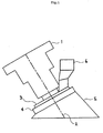
- Fig 1 represents apparatus for performing the method of the present invention.
- the apparatus comprises a beam delivery system (1) which in turn comprises means for generating and directing one or more laser beams and means for generating and directing positive gas pressure.
- the broken line (2) indicates the direction of the laser beam and gas jet generated by the beam delivery system.
- the beam delivery system is mounted on a central boss (3) which is housed within a bearing (4).
- a cowl (5) is attached to the bearing (4).
- Also mounted on the central boss (3) is a connection (6) to an extraction device which draws fumes from within the cowl (5) and removes them to an air purification system (not shown).
- the laser used was a Coherent Diamond 64 pulsed CO 2 industrial laser (power range 10-150 watts, optimum focal distance 5mm), mounted on a gantry motion system. The following parameters were used for cutting. Pulse On-Time 25 ⁇ s Maximum Pulse Power 10% Minimum Pulse Power 5% Laser-Membrane Dist. 5mm Cutting Speed 50mm/s
- the membranes were also cut in curved lines with identical results.
- the membrane was successfully cut and bonded.
- the membrane was successfully cut and bonded.
- the laser used was a Synrad sealed, continuous wave CO 2 laser.
- the trials were performed on a 100mm test piece on a polyethylene board through a galvanometer beam delivery system.
- the laser used was a 50W unit with one rod disconnected, thus effectively operating as a standard 25W unit.
- the actual beam power was measured using a calibrated laser intensity meter (the maximum laser power was found to be 30W).
- the results of the cutting trials are given below: Actual Beam Power (Watts) Cutting Speed (mm/s) Membrane Material Comments 30 20 FEP Cut Weak bond 18 20 FEP Cut Good bond 18 20 NafionTM Cut Very good bond
Landscapes
- Engineering & Computer Science (AREA)
- Mechanical Engineering (AREA)
- Physics & Mathematics (AREA)
- Health & Medical Sciences (AREA)
- Toxicology (AREA)
- Optics & Photonics (AREA)
- Electromagnetism (AREA)
- Thermal Sciences (AREA)
- Fluid Mechanics (AREA)
- Sustainable Energy (AREA)
- General Chemical & Material Sciences (AREA)
- Sustainable Development (AREA)
- Life Sciences & Earth Sciences (AREA)
- Chemical & Material Sciences (AREA)
- Chemical Kinetics & Catalysis (AREA)
- Electrochemistry (AREA)
- Manufacturing & Machinery (AREA)
- Lining Or Joining Of Plastics Or The Like (AREA)
- Manufacture Of Macromolecular Shaped Articles (AREA)
- Laser Beam Processing (AREA)
- Treatments Of Macromolecular Shaped Articles (AREA)
- Separation Using Semi-Permeable Membranes (AREA)
- Counters In Electrophotography And Two-Sided Copying (AREA)
- Printers Characterized By Their Purpose (AREA)
- Dot-Matrix Printers And Others (AREA)
Abstract
Description
- The present invention relates to a method for cutting a fluorinated polymer membrane and simultaneously joining it to a polyolefin polymeric supporting frame. Such a method may be useful in processes for the manufacture of filters, heat exchangers and electrochemical devices. In the latter case, the supporting frame may further comprise an electrode attached thereto so that the resultant frame/electrode/membrane combination forms a sub-assembly which may then be stacked together with other identical sub-assemblies to form an array of electrochemical cells, each cell thus comprising two bipolar electrodes with a membrane positioned therebetween so as to define separate anolyte-containing and catholyte-containing chambers within each cell. Such assemblies are well known to those skilled in the art and they may be used as fuel cells, electrolysers and secondary batteries.
- The incorporation of a polymeric membrane onto a supporting frame must satisfy a number of requirements. Firstly, the membrane must be accurately cut to the correct shape so that it fits the shape of the supporting frame. Secondly, the membrane must be accurately positioned on the supporting frame and its position must be verified as being correct prior to its attachment to the supporting frame. This second requirement becomes especially difficult to achieve as the size of the membrane and frame increases. The membranes are often very thin making them difficult to handle. Preferably, the first and second requirements are satisfied simultaneously by cutting the membrane in situ. Thirdly, the membrane must be attached to the supporting frame with sufficient strength to allow handling of the complete sub-assembly, for example, during stacking to form an array of electrochemical cells.
- More particularly, the present invention relates to a method for the attachment of a fluorinated polymer ion-exchange membrane onto a polymeric supporting frame. The supporting frame is preferably made of a single polyolefin polymer. This creates particular problems with regard to the requirements outlined above. With regard to the third requirement, the physical and chemical characteristics of fluorinated polymer ion-exchange membranes are very different from those of hydrocarbon polymers thus making it difficult to attach the two together. Fluorinated polymer ion-exchange membranes are not thermoplastic polymers, in contrast to simple hydrocarbon polymers. They are also hydrophilic, whereas hydrocarbon polymers are hydrophobic. These types of membranes can also be sensitive to humidity which places additional constraints on the cutting and aligning requirements of the method, i.e. these requirements must be satisfied quickly with minimum handling of the membrane. Another problem arises when the sub-assembly is to comprise a fluorinated polymer ion-exchange membrane. The chemical and physical properties of these membranes allow chemical species to wick through their thickness to the edges where they may leak out into unwanted areas of the sub-assembly causing both a loss of electrolyte and resultant contamination of the surroundings of the cells. Thus the edges of the membrane should preferably be de-functionalised in some way so as to prevent this wicking effect.
- Known methods for cutting the membrane to the required shape include the use of a cutting die formed into the required shape, or the use of cutting knives of various types. However, especially as size increases, these methods are often not suitable for simultaneous aligning of the cut membrane on the frame, i.e. in situ cutting. Accordingly they require further handling of the membrane in order to position it prior to attachment to the frame. Furthermore, they involve physical contact between cutting edges and the membrane which may result in misalignment of, or damage to, the membrane.
- Known methods for monitoring the correct alignment of the cut membrane on the supporting frame include the use of a laser triangulation system, however this is a costly and cumbersome technique. As mentioned above it would be preferable to use a method which allows cutting of the membrane in situ. This would obviate the need for the extra steps of aligning the membrane on the frame and then checking that the alignment is correct.
- A number of methods are known for attaching a fluorinated polymer membrane onto a polymeric frame. Plastic rivets may be used to create a permanent mechanical attachment to the frame. However, this method suffers from the disadvantages that it involves the extra step of punching holes in the membrane and it also results in local attachment only. Glues such as those based on silane compounds may also be used. However, the differing chemical properties of the fluorinated polymer membranes and frame polymers to which the present invention is particularly directed mean that selection of a glue which is compatible with both materials is very difficult. Furthermore, when the method of the present invention is directed toward the manufacture of sub-assemblies for forming electrochemical cells, it is preferable that the glue selected be chemically stable in the aggressive chemical environments commonly found in such electrochemical cells. Welding of the two polymers by melting them in the vicinity of the desired point of attachment is also known but is again unsuitable for the fluorinated polymer ion-exchange membrane and frame polymers to which the present invention is particularly directed because of their different thermal responses.
- The wicking problem associated with the use of polymeric ion-exchange membranes may be addressed by the application of fluorinated greases to the edges of the membrane, however, this is a messy and unreliable solution.
- It would be advantageous to achieve a method for the attachment of a fluorinated polymer membrane onto a polyolefin polymeric supporting frame which addresses all the requirements outlined above simultaneously.
- Accordingly, the present invention provides a method for cutting a fluorinated polymer membrane and simultaneously joining it to a polyolefin polymer frame, the method comprising the steps of;
- (i) contacting a fluorinated polymer membrane with a polyolefin polymer frame at the point where a cut and join is desired, and
- (ii) directing at least one laser beam onto the point of contact between the membrane and the frame so as to cut the membrane and effect a join to the frame.
-
- The present method allows cutting of the membrane to take place in situ, thus obviating the need for subsequent alignment of the cut membrane on the frame prior to joining. Furthermore, the use of a laser to cut the membrane is surprisingly found to simultaneously effect a join between the edge of the membrane and the frame. The join is found to be of sufficient strength and durability to allow subsequent handling of the membrane/frame sub-assembly.
- Examples of fluorinated polymers, membranes of which may be cut and simultaneously joined to a polymer using this method, include polytetrafluoroethylene, polyhexafluoropropylene, tetrafluoroethylene-hexafluoropropylene copolymer, tetrafluoroethylene-propylene copolymer, tetrafluoroethylene-ethylene copolymer, hexafluoropropylene-propylene copolymer hexafluoropropylene-ethylene copolymer, polyvinylidene fluoride, vinylidene fluoride tetrafluoroethylene copolymer, vinylidene fluoride hexafluoropropylene copolymer, polyvinyl fluoride, tetrafluoroethylene-perfluoroalkyl vinyl ether copolymer, polyvinylidene-hexafluoropropylene copolymer, chlorotrifluoroethylene-ethylene copolymer, chlorotrifluoroethylene-propylene copolymer, or perfluoroalkoxy copolymer.
- In a preferred embodiment of the present invention the fluorinated polymer membrane is a fluorinated polymer ion-exchange membrane and even more preferably the fluorinated polymer membrane is a fluorinated polymer cation-exchange membrane. Fluorinated polymer ion-exchange membranes may be formed from any of the fluorinated polymers described above with suitably functionalised monomer units grafted thereon. Suitably functionalised monomer units are well known to those skilled in the art and their structures are variable, however they essentially comprise an unsaturated functional group such as a vinyl group and an ion-exchange group such as a sulfonate or carboxylate group. Preferably the membrane is a hydrolysed copolymer of tetrafluoroethylene and a perfluoro-vinyl ether monomer comprising a cation-exchange group. Examples of preferred cation exchange membranes include copolymers of tetrafluoroethylene and a sulfonated or carboxylated perfluoro-vinyl ether such as those sold under the trade names of Nafion™ (Du Pont), Flemion™ (Asahi Glass)and Aciplex™ (Asahi Chemical).
- Preferably, the thickness of the membrane is in the range of from 25µm to 300µm, more preferably from 30µm to 200µm, even more preferably from 50µm to 150µm.
- It is possible that the membrane to be attached to the frame may also comprise an electrode attached thereto. Such membrane/electrode assemblies are well known in the art and all references to a membrane in this specification are intended to include such assemblies.
- It will be appreciated that the polyolefin polymeric frame may be formed from a wide range of polymers or copolymers. Suitable polymers include those selected from polyethylene, polypropylene, polystyrene and copolymer blends of two or more of polyethylene, polypropylene and polystyrene, and many others. The selection of a hydrogenated polymer frame material is particularly advantageous. This is because pyrolysis of perfluorinated polymers carries with it the possibility of the formation of perfluorisobutene (PFIB) which is highly toxic. Co-pyrolysis with hydrogenated material is found to produce little or no PFIB. It is believed that this is due to the rapid addition of hydrogen radicals to fluorocarbon radical intermediates formed by fluorocarbon degradation, thus preventing recombination of fluorocarbon radicals to yield PFIB.
- When the fluorinated polymer membrane is an ion exchange membrane the present method not only cuts the membrane and simultaneously joins it to the frame but surprisingly is also found to effect de-functionalisation of the cut edge of the membrane. The term de-functionalisation is intended to mean that the nature of the ion exchange membrane is altered in some way so that it no longer exhibits the same characteristics. In particular, it means that chemical species are no longer able to wick through the thickness of the membrane. The de-functionalisation of the membrane can be confirmed by staining the membrane with methylene blue which is a cationic dye. The de-functionalised region is not stained by the dye whilst the unaffected region is stained a deep blue colour. Thus, the problem of wicking associated with the use of such membranes is also addressed by the method of the present invention.
- It will be understood that the laser source may be selected from a number of different types of laser and that the laser beam may be either pulsed or continuous. Preferably however the laser used is a pulsed CO2 laser because the wavelength of light generated by this laser is particularly suitable for cutting the preferred polymer membranes mentioned above.
- It will also be appreciated that the power of the laser beam to be used and the cutting speed achievable are interrelated and also dependent upon other parameters, in particular, upon the chemical structure and the thickness of the membrane. However, for the purposes of cutting the preferred polymer membranes mentioned above which are of a thickness in the range of from 25µm to 300µm the power of the laser beam is preferably in the range of from 10W to 150W and the cutting speed is preferably in the range of from 10mm/s to 1000mm/s, more preferably from 20mm/s to 500mm/s, even more preferably from 50mm/s to 200mm/s and most preferably from 100mm/s to 200mm/s.
- The focus of the laser beam may also be varied, depending upon the other set-up parameters, so as to provide a broader or narrower width of irradiation of the membrane along the line of the cut/join. Preferably the width of the beam as it impinges on the membrane is in the range of from 50µm to 450µm, more preferably from 250µm to 400µm. Depending on the identity of the materials being used it is sometimes found that for a given beam power, a narrower, i.e. more focussed, beam will provide a faster cutting speed but a weaker join whilst a wider, i.e. more diffuse, beam will provide a stronger join but at a slower cutting speed. A wider beam also aids the physical separation of the functional membrane from the scrap membrane. A narrow beam allows a faster cutting speed but ease of physical separation of the functional membrane from the scrap membrane is sacrificed. The present invention is not necessarily limited to the use of a single laser beam and it will be appreciated by those skilled in the art that other beam arrangements such as a dual beam or concentric multiple beams may also be employed. In particular the dual beam method may comprise one type of beam for providing a fast cut together with another type of beam for providing a stronger join.
- The cutting process as performed by the method of the present invention often generates debris which, if not controlled, could contaminate the membrane and/or frame surfaces. Accordingly, in a preferred embodiment, the method of the present invention involves use of a shielding means which is situated adjacent to the point of contact of the laser beam with the membrane and which moves in synchrony with the laser beam as it travels along the cutting line. The shielding means thus prevents debris from contaminating areas around the cutting line.
- In order for the method described above to effect a join between the fluorinated polymer membrane and the polymer frame it is essential that there be contact between the membrane and the frame at the point of cutting. The contact between the membrane and the frame may be achieved by pressure means which urges the membrane into contact with the frame at the point of cutting. Suitable pressure means may comprise a plate of substantially the same perimeter size and shape as the membrane. The plate can be pressed against the membrane to ensure contact between the membrane and frame at the point of cutting. Such a plate may also be advantageously employed in combination with other types of pressure means because it provides the additional benefit of shielding the major central portion of the membrane from debris generated by the cutting of the membrane. Suitable pressure means may alternatively comprise a roller which impinges on the membrane at a position adjacent to the laser beam, or one or more air jets which apply positive gas pressure on the membrane at a position adjacent to the laser beam, or means for providing a vacuum between the membrane and the frame at or adjacent to the point where the laser beam impinges on the membrane.
- In a particularly preferred embodiment, suitable pressure means may be provided by applying positive air pressure, such as an air jet, to a point adjacent to the point where the laser beam impinges on the membrane so as to bring the membrane and substrate polymer into physical contact. Preferably, the laser beam and the positive gas pressure are directed at an angle of from 110 to 120 degrees to the plane of the membrane, pointing in a direction away from the centre of the membrane. The use of positive gas pressure not only provides suitable pressure means to bring the membrane and substrate polymer into physical contact. The positive gas pressure also aids the lifting of the waste membrane whilst minimising the removal effects upon the functional piece of membrane. It also helps to remove fumes produced by the process from the vicinity of the membrane and frame.
- The present invention also encompasses within its scope apparatus for performing the method of the present invention, said apparatus comprising a beam delivery system which comprises means for generating and directing one or more laser beams onto the membrane and means for generating and directing positive gas pressure to a point at or adjacent to the point where said one or more laser beams impinge on the membrane.
- The lasering operation may produce large volumes of fumes and therefore, in a preferred embodiment, the apparatus also comprises a cowl which encompasses the laser beam delivery area and an extraction device for conveying fumes away from the point of cutting and joining. Said cowl is preferably shaped such that the eccentric profile allows capture of the positive air pressure's 'bounced' trajectory.
- In a preferred embodiment the means for generating and directing one or more laser beams and the means for generating and directing positive gas pressure are constructed so as to provide a laser beam and a gas jet which are substantially parallel to one another.
- When the cutting and joining method follows a path which is not linear, the orientation of the beam delivery system must change relative to the membrane during the cutting and joining process. Therefore, when present, the orientation of the cowl must also change to maintain a uniform void between the cowl and the membrane so as not to drastically alter the dynamics of the fume transfer. Thus, in a preferred embodiment, the extraction device and the beam delivery system are mounted on a central boss, (through which the fumes may be removed) said boss being housed within a bearing on which the main body of the cowl may be mounted. The rotating portion of the cowl is preferably counterbalanced so as to allow the cowl to remain flush relative to the membrane regardless of the boss position.
- The present invention also includes within its scope a sub-assembly comprising a polyolefin polymer frame and a fluorinated polymer membrane which has been cut and attached thereto by the method described above and also a stack of one or more such sub-assemblies arranged so as to form an array of electrochemical cells for use as a fuel cell, electrolyser or secondary battery.
- The present invention will be further described with reference to Fig 1 which represents apparatus for performing the method of the present invention.
- Referring to Fig 1, the apparatus comprises a beam delivery system (1) which in turn comprises means for generating and directing one or more laser beams and means for generating and directing positive gas pressure. The broken line (2) indicates the direction of the laser beam and gas jet generated by the beam delivery system. The beam delivery system is mounted on a central boss (3) which is housed within a bearing (4). A cowl (5) is attached to the bearing (4). Also mounted on the central boss (3) is a connection (6) to an extraction device which draws fumes from within the cowl (5) and removes them to an air purification system (not shown).
- The present invention will be further described with reference to the following examples:
- Laser cutting and joining of membranes to a polyethylene substrate was carried out on the following membrane materials:
- Flemion SH80™ (80µm thick, dried unconstrained)
- Flemion SH80™ (80µm thick, dried constrained)
- Nafion 115™ (125µm thick)
-
- The laser used was a Coherent Diamond 64 pulsed CO2 industrial laser (power range 10-150 watts, optimum focal distance 5mm), mounted on a gantry motion system. The following parameters were used for cutting.
Pulse On-Time 25µs Maximum Pulse Power 10% Minimum Pulse Power 5% Laser-Membrane Dist. 5mm Cutting Speed 50mm/s - Each membrane was laid over a flat polyethylene substrate and cut in a straight line in directions both parallel to and orthogonal to the material axis. The results are summarised in the table below:
Material Cut direction Clean Cut? Bonded? Flemion Parallel Yes Yes SH80™-constrained Orthogonal Yes Yes Flemion Parallel No Partially SH80™-unconstrained Orthogonal Yes Yes Nafion 115™ Parallel Yes Yes Orthogonal Yes Yes - The membranes were also cut in curved lines with identical results.
- A further test using the method of example 1 was carried out on Flemion SH80™ material using the following laser set-up parameters:
Pulse On-Time 25µs Maximum Pulse Power 100% Minimum Pulse Power 80% Laser-Membrane Dist. 5mm Cutting Speed 1000mm/s - The membrane was successfully cut and bonded.
- A further test using the method of example 1 was carried out on Flemion SH80™ material using the following laser set-up parameters:
Pulse On-Time 25µs Maximum Pulse Power 10% Minimum Pulse Power 10% Laser-Membrane Dist. 25mm Cutting Speed 35mm/s - The membrane was successfully cut and bonded.
- Laser cutting and joining of membranes to a polyethylene substrate was carried out on the following membrane materials:
- Fluorinated ethylene-propylene copolymer (FEP) film (100µm thick, 100mm wide)
- Nafion 115™(120µm thick, 100mm wide)
-
- The laser used was a Synrad sealed, continuous wave CO2 laser. The trials were performed on a 100mm test piece on a polyethylene board through a galvanometer beam delivery system. The laser used was a 50W unit with one rod disconnected, thus effectively operating as a standard 25W unit. The actual beam power was measured using a calibrated laser intensity meter (the maximum laser power was found to be 30W). The results of the cutting trials are given below:
Actual Beam Power (Watts) Cutting Speed (mm/s) Membrane Material Comments 30 20 FEP Cut Weak bond 18 20 FEP Cut Good bond 18 20 Nafion™ Cut Very good bond - Laser cutting and joining of a rectangular portion of membrane with four curved corners was carried out using a pulsed laser with the following materials and laser parameters:
- Membrane = Nafion™ 115 and FEP
- Frame material = high density polyethylene
- Laser power = 60W for straight edges
4W for corners - Cutting speed = 100mm/s for straight edges
40mm/s for corners. -
Claims (27)
- A method for cutting a fluorinated polymer membrane and simultaneously joining it to a polyolefin polymer frame, the method comprising the steps
of;(i) contacting a fluorinated polymer membrane with a polyolefin polymer frame at the point where a cut and join is desired, and(ii) directing at least one laser beam onto the point of contact between the membrane and the frame so as to cut the membrane and effect a join to the frame. - A method according to claim 1 wherein the fluorinated polymer membrane is made from a fluorinated polymer selected from polytetrafluoroethylene, polyhexafluoropropylene, tetrafluoroethylene-hexafluoropropylene copolymer, tetrafluoroethylene-propylene copolymer, tetrafluoroethylene-ethylene copolymer, hexafluoropropylene-propylene copolymer, hexafluoropropylene-ethylene copolymer, polyvinylidene fluoride, vinylidene fluoride tetrafluoroethylene copolymer, vinylidene fluoride hexafluoropropylene copolymer, polyvinyl fluoride, tetrafluoroethylene-perfluoroalkyl vinyl ether copolymer, polyvinylidene-hexafluoropropylene copolymer, chlorotrifluoroethylene-ethylene copolymer, chlorotrifluoroethylene-propylene copolymer, or perfluoroalkoxy copolymer.
- A method according to claim 1 wherein the fluorinated polymer membrane is a fluorinated polymer ion exchange membrane.
- A method according to claim 3 wherein the fluorinated polymer ion exchange membrane is made from a fluorinated polymer selected from polytetrafluoroethylene, polyhexafluoropropylene, tetrafluoroethylene-hexafluoropropylene copolymer, tetrafluoroethylene-propylene copolymer, tetrafluoroethylene-ethylene copolymer, hexafluoropropylene-propylene copolymer, hexafluoropropylene-ethylene copolymer, polyvinylidene fluoride, vinylidene fluoride tetrafluoroethylene copolymer, vinylidene fluoride hexafluoropropylene copolymer, polyvinyl fluoride, tetrafluoroethylene-perfluoroalkyl vinyl ether copolymer, polyvinylidene-hexafluoropropylene copolymer, chlorotrifluoroethylene-ethylene copolymer, chlorotrifluoroethylene-propylene copolymer, or perfluoroalkoxy copolymer with suitably functionalised monomer units grafted thereon.
- A method according to claim 3 or claim 4 wherein the fluorinated polymer ion-exchange membrane is a fluorinated polymer cation-exchange membrane.
- A method according to claim 5 wherein the fluorinated polymer cation-exchange membrane is a hydrolysed copolymer of tetrafluoroethylene and a perfluoro-vinyl ether monomer comprising a cation-exchange group.
- A method according to any one of claims 3 to 6 wherein the fluorinated polymer ion-exchange membrane is de-functionalised in the vicinity of the cut edge so as to reduce the wicking of fluid through the cut edge.
- A method according to any one of the preceding claims wherein the thickness of the membrane is in the range of from 25µm to 300µm.
- A method according to any one of the preceding claims wherein the frame is made from a polyolefin polymer selected from polyethylene, polypropylene, polystyrene or a copolymer blend of two or more of polyethylene, polypropylene and polystyrene.
- A method according to any one of the preceding claims wherein the laser beam is either pulsed or continuous.
- A method according to any one of the preceding claims wherein the power of the laser beam is in the range of from 10 to 150W.
- A method according to any one of the preceding claims wherein the speed of travel of the laser beam along the cutting and joining line is in the range of from 10mm/s to 1000mm/s.
- A method according to any one of the preceding claims wherein the width of the beam at the point where it impinges on the membrane is in the range of from 50µm to 450µm.
- A method according to any one of the preceding claims wherein the laser used is a pulsed CO2 laser.
- A method according to any one of the preceding claims wherein there is provided shielding means which is situated adjacent to the point of contact of the laser beam with the membrane and which moves in synchrony with the laser beam as it travels along the cutting line.
- A method according to any one of the preceding claims wherein the contact between the fluorinated polymer membrane and the hydrocarbon polymer frame is achieved by pressure means which urges the membrane into contact with the frame.
- A method according to claim 16 wherein the pressure means comprises a plate of substantially the same perimeter size and shape as the membrane which can be pressed against the membrane to ensure contact between the membrane and frame at the point of cutting.
- A method according to claim 16 wherein the pressure means comprises a roller which impinges on the membrane at a position adjacent to the laser beam.
- A method according to claim 16 wherein the pressure means comprises one or more gas jets which apply positive air pressure on the membrane at a position adjacent to the laser beam.
- A method according to claim 19 wherein the laser beam and gas jet are directed at an angle of from 110 to 120 degrees to the plane of the membrane, pointing in a direction away from the centre of the membrane.
- A method according to claim 16 wherein the pressure means comprises means for providing a vacuum between the membrane and the frame at or adjacent to the point where the laser beam impinges on the membrane.
- A method according to any one of claims 16 and 18 to 21 which additionally utilises a plate of substantially the same size and shape as the membrane which impinges thereon and acts as a shield to prevent debris from the cutting procedure from contaminating the main central portion of the membrane.
- A method according to any one of the preceding claims wherein the laser beam is in the form of a single beam, dual beams or concentric multiple beams.
- A method according to any one of the preceding claims wherein the membrane comprises an electrode attached thereto.
- Apparatus for cutting a fluorinated polymer membrane and simultaneously joining it to a polyolefin polymer frame, the apparatus comprising:wherein the means for generating and directing one or more laser beams and the means for generating and directing positive gas pressure are constructed so as to provide a laser beam and a gas jet which are substantially parallel to one another.(i) a beam delivery system which comprises means for generating and directing one or more laser beams onto the membrane at an angle of from 110 to 120 degrees to the plane of the membrane pointing in a direction away from the centre of the membrane and means for generating and directing positive air pressure to a point at or adjacent to the point where said one or more laser beams impinge on the membrane,(ii) a cowl which encompasses the laser beam delivery area, and(iii)a pump for conveying fumes away from the point of cutting and joining;
- A sub-assembly comprising a polyolefin polymer frame and a fluorinated polymer membrane which has been cut and joined thereto by the method claimed in any one of claims 1 to 24.
- An electrochemical apparatus formed from a plurality of sub-assemblies as claimed in claim 26.
Applications Claiming Priority (3)
| Application Number | Priority Date | Filing Date | Title |
|---|---|---|---|
| GBGB9816422.1A GB9816422D0 (en) | 1998-07-28 | 1998-07-28 | Laser cutting and joining |
| GB9816422 | 1998-07-28 | ||
| PCT/GB1999/002335 WO2000007254A1 (en) | 1998-07-28 | 1999-07-20 | Laser cutting and joining a fluorinated polymer membrane to a polymer frame |
Publications (2)
| Publication Number | Publication Date |
|---|---|
| EP1105930A1 EP1105930A1 (en) | 2001-06-13 |
| EP1105930B1 true EP1105930B1 (en) | 2003-03-12 |
Family
ID=10836310
Family Applications (1)
| Application Number | Title | Priority Date | Filing Date |
|---|---|---|---|
| EP99934890A Expired - Lifetime EP1105930B1 (en) | 1998-07-28 | 1999-07-20 | Laser cutting and joining a fluorinated polymer membrane to a polymer frame |
Country Status (24)
| Country | Link |
|---|---|
| EP (1) | EP1105930B1 (en) |
| JP (1) | JP2002521250A (en) |
| KR (1) | KR20010071054A (en) |
| CN (1) | CN1316110A (en) |
| AT (1) | ATE234513T1 (en) |
| AU (1) | AU757498B2 (en) |
| BG (1) | BG105279A (en) |
| BR (1) | BR9912445A (en) |
| CA (1) | CA2338208A1 (en) |
| CZ (1) | CZ2001201A3 (en) |
| DE (1) | DE69905908T2 (en) |
| DK (1) | DK1105930T3 (en) |
| ES (1) | ES2192390T3 (en) |
| GB (2) | GB9816422D0 (en) |
| HU (1) | HUP0102999A3 (en) |
| IL (2) | IL140842A0 (en) |
| NO (1) | NO20010455L (en) |
| NZ (1) | NZ509677A (en) |
| PL (1) | PL345690A1 (en) |
| PT (1) | PT1105930E (en) |
| SK (1) | SK1332001A3 (en) |
| TW (1) | TW461136B (en) |
| WO (1) | WO2000007254A1 (en) |
| ZA (1) | ZA200100450B (en) |
Families Citing this family (12)
| Publication number | Priority date | Publication date | Assignee | Title |
|---|---|---|---|---|
| JP2002331587A (en) * | 2001-05-11 | 2002-11-19 | Uchiya Thermostat Kk | Film bonding method |
| JP2005529327A (en) | 2002-06-11 | 2005-09-29 | ケムパック エイ/エス | Disposable cartridge for characterizing particles suspended in liquid |
| US6998008B2 (en) | 2003-07-15 | 2006-02-14 | Lexmark International, Inc. | Method and apparatus for attaching an ink jet filter to an ink cartridge |
| CA2855108A1 (en) | 2005-02-10 | 2006-08-17 | Koninklijke Philips Electronics N.V. | Dual sample cartridge and method for characterizing particles in liquid |
| AU2006212607B2 (en) | 2005-02-10 | 2010-12-09 | Koninklijke Philips Electronics N.V. | Dual sample cartridge and method for characterizing particle in liquid |
| JP2008093685A (en) * | 2006-10-11 | 2008-04-24 | Hitachi Ltd | Laser cutting device for electrolyte membrane for fuel cell |
| WO2008114470A1 (en) * | 2007-03-16 | 2008-09-25 | Sharp Kabushiki Kaisha | Method for cutting plastic substrate, and apparatus for cutting plastic substrate |
| JP2009291943A (en) * | 2008-06-02 | 2009-12-17 | Nitto Denko Corp | Method for producing sheet junction body |
| JP5408972B2 (en) * | 2008-11-26 | 2014-02-05 | 日東電工株式会社 | Sheet assembly manufacturing method |
| JP5408971B2 (en) * | 2008-11-26 | 2014-02-05 | 日東電工株式会社 | Sheet assembly manufacturing method |
| JP6020535B2 (en) * | 2013-12-27 | 2016-11-02 | トヨタ自動車株式会社 | Manufacturing method and manufacturing apparatus for electrode frame assembly for fuel cell |
| CN117673427B (en) * | 2022-08-26 | 2025-01-14 | 比亚迪股份有限公司 | Battery cell preparation system, battery cell preparation method, laminated battery cell and battery |
Family Cites Families (17)
| Publication number | Priority date | Publication date | Assignee | Title |
|---|---|---|---|---|
| US3560291A (en) * | 1964-03-27 | 1971-02-02 | Mobil Oil Corp | Bonding thermoplastic resin films by means of radiation from a laser source |
| GB2095615B (en) * | 1981-03-25 | 1984-06-20 | Bingley A J Ltd | Apparatus for cutting and/or welding laminar thermoplastics material |
| DE3621030C2 (en) * | 1986-06-24 | 1995-01-05 | Alkor Gmbh | Method and device for welding and / or separation welding using laser beams |
| US4847462A (en) * | 1986-11-06 | 1989-07-11 | American Fluoroseal Corporation | Method and apparatus for making fluorocarbon film plastic bags using a laser |
| US4945203A (en) * | 1986-11-06 | 1990-07-31 | American Fluoroseal Corporation | Method and apparatus for making fluorocarbon film plastic bags using a laser |
| FR2627409A1 (en) * | 1988-02-24 | 1989-08-25 | Lectra Systemes Sa | LASER CUTTING APPARATUS WITH A FUME EXHAUST DEVICE |
| JPH0299293A (en) * | 1988-10-04 | 1990-04-11 | Shinko Kogyo Co Ltd | laser processing head |
| JPH0299292A (en) * | 1988-10-04 | 1990-04-11 | Shinko Kogyo Co Ltd | Laser processing nozzle |
| GB9009582D0 (en) * | 1990-04-27 | 1990-06-20 | Crosfield Electronics Ltd | Method of shaping and bonding plastics materials |
| DE9215287U1 (en) * | 1992-03-31 | 1993-03-04 | Wissner, Rolf, Dipl.-Ing., 3400 Göttingen | Head for laser milling and engraving machines for the processing of essentially plate-shaped material |
| JPH06114943A (en) * | 1992-10-02 | 1994-04-26 | Mitsubishi Heavy Ind Ltd | Method for fusion bonding fluororesin film |
| DE4331262C2 (en) * | 1993-09-15 | 1996-05-15 | Wissner Rolf | Laser machine for machining a workpiece and method for controlling a laser machine |
| DE4428938A1 (en) * | 1994-08-16 | 1996-03-07 | Hoechst Ag | Joining unbondable, unweldable polymer to bondable, weldable polymer |
| CA2215977A1 (en) * | 1995-03-23 | 1996-09-26 | Arthur L. Goldstein | Improvements in membrane processes including electrodialysis |
| US5645665A (en) * | 1995-05-26 | 1997-07-08 | The Regents Of The University Of California Office Of Technology Transfer | Intraocular lens fabrication |
| DE29518138U1 (en) * | 1995-11-15 | 1996-04-18 | Brandstetter, Heinz Peter, Wien | Laser engraving and cutting device |
| US5772817A (en) * | 1997-02-10 | 1998-06-30 | Micro Lithography, Inc. | Optical pellicle mounting system |
-
1998
- 1998-07-28 GB GBGB9816422.1A patent/GB9816422D0/en not_active Ceased
-
1999
- 1999-07-20 DE DE69905908T patent/DE69905908T2/en not_active Expired - Fee Related
- 1999-07-20 ES ES99934890T patent/ES2192390T3/en not_active Expired - Lifetime
- 1999-07-20 SK SK133-2001A patent/SK1332001A3/en unknown
- 1999-07-20 AU AU50524/99A patent/AU757498B2/en not_active Ceased
- 1999-07-20 EP EP99934890A patent/EP1105930B1/en not_active Expired - Lifetime
- 1999-07-20 IL IL14084299A patent/IL140842A0/en unknown
- 1999-07-20 JP JP2000562966A patent/JP2002521250A/en active Pending
- 1999-07-20 CZ CZ2001201A patent/CZ2001201A3/en unknown
- 1999-07-20 WO PCT/GB1999/002335 patent/WO2000007254A1/en not_active Ceased
- 1999-07-20 AT AT99934890T patent/ATE234513T1/en not_active IP Right Cessation
- 1999-07-20 CN CN99810375A patent/CN1316110A/en active Pending
- 1999-07-20 DK DK99934890T patent/DK1105930T3/en active
- 1999-07-20 CA CA002338208A patent/CA2338208A1/en not_active Abandoned
- 1999-07-20 GB GB9917034A patent/GB2340064B/en not_active Expired - Fee Related
- 1999-07-20 PL PL99345690A patent/PL345690A1/en unknown
- 1999-07-20 NZ NZ509677A patent/NZ509677A/en unknown
- 1999-07-20 BR BR9912445-9A patent/BR9912445A/en not_active IP Right Cessation
- 1999-07-20 KR KR1020017001220A patent/KR20010071054A/en not_active Withdrawn
- 1999-07-20 HU HU0102999A patent/HUP0102999A3/en unknown
- 1999-07-20 PT PT99934890T patent/PT1105930E/en unknown
- 1999-10-14 TW TW088117781A patent/TW461136B/en not_active IP Right Cessation
-
2001
- 2001-01-10 IL IL14084101A patent/IL140841A0/en unknown
- 2001-01-16 ZA ZA200100450A patent/ZA200100450B/en unknown
- 2001-01-26 NO NO20010455A patent/NO20010455L/en not_active Application Discontinuation
- 2001-02-21 BG BG105279A patent/BG105279A/en unknown
Also Published As
| Publication number | Publication date |
|---|---|
| CZ2001201A3 (en) | 2001-10-17 |
| TW461136B (en) | 2001-10-21 |
| DK1105930T3 (en) | 2003-07-14 |
| BR9912445A (en) | 2001-04-17 |
| DE69905908T2 (en) | 2003-12-04 |
| HUP0102999A3 (en) | 2002-02-28 |
| PL345690A1 (en) | 2002-01-02 |
| AU5052499A (en) | 2000-02-21 |
| GB2340064B (en) | 2001-01-03 |
| EP1105930A1 (en) | 2001-06-13 |
| ZA200100450B (en) | 2002-01-16 |
| KR20010071054A (en) | 2001-07-28 |
| ES2192390T3 (en) | 2003-10-01 |
| CN1316110A (en) | 2001-10-03 |
| HUP0102999A2 (en) | 2001-12-28 |
| NO20010455D0 (en) | 2001-01-26 |
| PT1105930E (en) | 2003-07-31 |
| NO20010455L (en) | 2001-03-19 |
| WO2000007254A1 (en) | 2000-02-10 |
| SK1332001A3 (en) | 2001-07-10 |
| CA2338208A1 (en) | 2000-02-10 |
| ATE234513T1 (en) | 2003-03-15 |
| BG105279A (en) | 2001-10-31 |
| GB2340064A (en) | 2000-02-16 |
| IL140841A0 (en) | 2002-02-10 |
| IL140842A0 (en) | 2002-02-10 |
| NZ509677A (en) | 2003-10-31 |
| AU757498B2 (en) | 2003-02-20 |
| DE69905908D1 (en) | 2003-04-17 |
| GB9917034D0 (en) | 1999-09-22 |
| JP2002521250A (en) | 2002-07-16 |
| GB9816422D0 (en) | 1998-09-23 |
Similar Documents
| Publication | Publication Date | Title |
|---|---|---|
| AU757498B2 (en) | Laser cutting and joining a fluorinated polymer membrane to a polymer frame | |
| CN110730702B (en) | Method and apparatus for high-throughput cutting of tape-type substrates, especially electrodes for batteries, into discrete pieces | |
| US6176953B1 (en) | Ultrasonic welding process | |
| CN104174995B (en) | Laser cutting device and laser cutting method | |
| KR20230109896A (en) | Electrode tab notching device | |
| US12463233B2 (en) | Cutting device, and lamination apparatus and lamination method for secondary battery comprising the same | |
| US20140014254A1 (en) | Method of Preparing a Fuel Cell Unitized Electrode Assembly by Ultrasonic Welding | |
| KR102386895B1 (en) | Laser processing apparatus and method thereof | |
| KR20220103068A (en) | Laser cutting apparatus | |
| KR20230006337A (en) | Electrode notching apparatus and method thereof | |
| KR101124327B1 (en) | Lithium Battery and its assembly method | |
| JP2015107514A (en) | Laser welding method and laser welding device | |
| JP5320522B2 (en) | ELECTROLYTE MEMBRANE FOR SOLID POLYMER FUEL CELL, METHOD FOR PRODUCING THE SAME, AND SOLID POLYMER FUEL CELL | |
| KR20180072964A (en) | Process for Preparing Battery Cell Comprising Ablation Step of Burr Using Fiber Pulse Type Laser | |
| CN113547753A (en) | Laser welding method for plastic | |
| KR102902592B1 (en) | Method of manufacturing lead tab for secondary battery | |
| CN110434463B (en) | Laser welding method for irradiation sample holder | |
| KR20220148471A (en) | Ultrasonic cutting device and method for manufacturing cylindrical battery | |
| JP6467788B2 (en) | Laser processing apparatus and laser processing method | |
| RU2001105915A (en) | LASER CUTTING OF A MEMBRANE FROM A FLUORinated POLYMER AND ITS ATTACHMENT TO A POLYMERIC FRAME | |
| JP2024092979A (en) | Manufacturing method for resin parts | |
| KR20230007181A (en) | A master jig equipped with laser pointer and stack cell process equipment setting method using the same | |
| KR20260029933A (en) | Electrode manufacturing device for secondary batteries and electrode manufacturing method for secondary batteries | |
| CN121665458A (en) | A cutting and edge-sealing process, a circuit board, and cutting and edge-sealing equipment. | |
| CN116568451A (en) | incision device |
Legal Events
| Date | Code | Title | Description |
|---|---|---|---|
| PUAI | Public reference made under article 153(3) epc to a published international application that has entered the european phase |
Free format text: ORIGINAL CODE: 0009012 |
|
| 17P | Request for examination filed |
Effective date: 20010227 |
|
| AK | Designated contracting states |
Kind code of ref document: A1 Designated state(s): AT BE CH CY DE DK ES FI FR GB GR IE IT LI LU MC NL PT SE |
|
| AX | Request for extension of the european patent |
Free format text: AL;LT;LV;MK;RO;SI |
|
| RAP1 | Party data changed (applicant data changed or rights of an application transferred) |
Owner name: REGENESYS TECHNOLOGIES LIMITED |
|
| GRAG | Despatch of communication of intention to grant |
Free format text: ORIGINAL CODE: EPIDOS AGRA |
|
| 17Q | First examination report despatched |
Effective date: 20020510 |
|
| GRAG | Despatch of communication of intention to grant |
Free format text: ORIGINAL CODE: EPIDOS AGRA |
|
| GRAH | Despatch of communication of intention to grant a patent |
Free format text: ORIGINAL CODE: EPIDOS IGRA |
|
| GRAH | Despatch of communication of intention to grant a patent |
Free format text: ORIGINAL CODE: EPIDOS IGRA |
|
| GRAA | (expected) grant |
Free format text: ORIGINAL CODE: 0009210 |
|
| AK | Designated contracting states |
Designated state(s): AT BE CH CY DE DK ES FI FR GB GR IE IT LI LU MC NL PT SE |
|
| AX | Request for extension of the european patent |
Extension state: AL LT LV MK RO SI |
|
| PG25 | Lapsed in a contracting state [announced via postgrant information from national office to epo] |
Ref country code: FI Free format text: LAPSE BECAUSE OF FAILURE TO SUBMIT A TRANSLATION OF THE DESCRIPTION OR TO PAY THE FEE WITHIN THE PRESCRIBED TIME-LIMIT Effective date: 20030312 |
|
| REG | Reference to a national code |
Ref country code: GB Ref legal event code: FG4D |
|
| REG | Reference to a national code |
Ref country code: CH Ref legal event code: EP |
|
| REG | Reference to a national code |
Ref country code: IE Ref legal event code: FG4D |
|
| REF | Corresponds to: |
Ref document number: 69905908 Country of ref document: DE Date of ref document: 20030417 Kind code of ref document: P |
|
| REG | Reference to a national code |
Ref country code: CH Ref legal event code: NV Representative=s name: E. BLUM & CO. PATENTANWAELTE |
|
| REG | Reference to a national code |
Ref country code: GR Ref legal event code: EP Ref document number: 20030401868 Country of ref document: GR |
|
| PGFP | Annual fee paid to national office [announced via postgrant information from national office to epo] |
Ref country code: PT Payment date: 20030630 Year of fee payment: 5 |
|
| REG | Reference to a national code |
Ref country code: SE Ref legal event code: TRGR |
|
| PGFP | Annual fee paid to national office [announced via postgrant information from national office to epo] |
Ref country code: GR Payment date: 20030702 Year of fee payment: 5 |
|
| PGFP | Annual fee paid to national office [announced via postgrant information from national office to epo] |
Ref country code: ES Payment date: 20030704 Year of fee payment: 5 |
|
| PGFP | Annual fee paid to national office [announced via postgrant information from national office to epo] |
Ref country code: IE Payment date: 20030710 Year of fee payment: 5 |
|
| PGFP | Annual fee paid to national office [announced via postgrant information from national office to epo] |
Ref country code: LU Payment date: 20030711 Year of fee payment: 5 Ref country code: GB Payment date: 20030711 Year of fee payment: 5 |
|
| PGFP | Annual fee paid to national office [announced via postgrant information from national office to epo] |
Ref country code: SE Payment date: 20030714 Year of fee payment: 5 Ref country code: DK Payment date: 20030714 Year of fee payment: 5 |
|
| REG | Reference to a national code |
Ref country code: DK Ref legal event code: T3 |
|
| PGFP | Annual fee paid to national office [announced via postgrant information from national office to epo] |
Ref country code: CH Payment date: 20030715 Year of fee payment: 5 |
|
| PGFP | Annual fee paid to national office [announced via postgrant information from national office to epo] |
Ref country code: BE Payment date: 20030717 Year of fee payment: 5 |
|
| PGFP | Annual fee paid to national office [announced via postgrant information from national office to epo] |
Ref country code: FR Payment date: 20030718 Year of fee payment: 5 |
|
| PG25 | Lapsed in a contracting state [announced via postgrant information from national office to epo] |
Ref country code: CY Free format text: LAPSE BECAUSE OF FAILURE TO SUBMIT A TRANSLATION OF THE DESCRIPTION OR TO PAY THE FEE WITHIN THE PRESCRIBED TIME-LIMIT Effective date: 20030720 |
|
| PGFP | Annual fee paid to national office [announced via postgrant information from national office to epo] |
Ref country code: AT Payment date: 20030729 Year of fee payment: 5 |
|
| PG25 | Lapsed in a contracting state [announced via postgrant information from national office to epo] |
Ref country code: MC Free format text: LAPSE BECAUSE OF NON-PAYMENT OF DUE FEES Effective date: 20030731 |
|
| PGFP | Annual fee paid to national office [announced via postgrant information from national office to epo] |
Ref country code: NL Payment date: 20030731 Year of fee payment: 5 |
|
| LTIE | Lt: invalidation of european patent or patent extension |
Effective date: 20030312 |
|
| PGFP | Annual fee paid to national office [announced via postgrant information from national office to epo] |
Ref country code: DE Payment date: 20030923 Year of fee payment: 5 |
|
| REG | Reference to a national code |
Ref country code: ES Ref legal event code: FG2A Ref document number: 2192390 Country of ref document: ES Kind code of ref document: T3 |
|
| ET | Fr: translation filed | ||
| PLBE | No opposition filed within time limit |
Free format text: ORIGINAL CODE: 0009261 |
|
| STAA | Information on the status of an ep patent application or granted ep patent |
Free format text: STATUS: NO OPPOSITION FILED WITHIN TIME LIMIT |
|
| 26N | No opposition filed |
Effective date: 20031215 |
|
| PG25 | Lapsed in a contracting state [announced via postgrant information from national office to epo] |
Ref country code: LU Free format text: LAPSE BECAUSE OF NON-PAYMENT OF DUE FEES Effective date: 20040720 Ref country code: IE Free format text: LAPSE BECAUSE OF NON-PAYMENT OF DUE FEES Effective date: 20040720 Ref country code: GB Free format text: LAPSE BECAUSE OF NON-PAYMENT OF DUE FEES Effective date: 20040720 Ref country code: AT Free format text: LAPSE BECAUSE OF NON-PAYMENT OF DUE FEES Effective date: 20040720 |
|
| PG25 | Lapsed in a contracting state [announced via postgrant information from national office to epo] |
Ref country code: SE Free format text: LAPSE BECAUSE OF NON-PAYMENT OF DUE FEES Effective date: 20040721 Ref country code: ES Free format text: LAPSE BECAUSE OF NON-PAYMENT OF DUE FEES Effective date: 20040721 |
|
| PG25 | Lapsed in a contracting state [announced via postgrant information from national office to epo] |
Ref country code: LI Free format text: LAPSE BECAUSE OF NON-PAYMENT OF DUE FEES Effective date: 20040731 Ref country code: CH Free format text: LAPSE BECAUSE OF NON-PAYMENT OF DUE FEES Effective date: 20040731 Ref country code: BE Free format text: LAPSE BECAUSE OF NON-PAYMENT OF DUE FEES Effective date: 20040731 |
|
| PG25 | Lapsed in a contracting state [announced via postgrant information from national office to epo] |
Ref country code: DK Free format text: LAPSE BECAUSE OF NON-PAYMENT OF DUE FEES Effective date: 20040802 |
|
| PG25 | Lapsed in a contracting state [announced via postgrant information from national office to epo] |
Ref country code: PT Free format text: LAPSE BECAUSE OF NON-PAYMENT OF DUE FEES Effective date: 20050120 |
|
| BERE | Be: lapsed |
Owner name: *REGENESYS TECHNOLOGIES LTD Effective date: 20040731 |
|
| PG25 | Lapsed in a contracting state [announced via postgrant information from national office to epo] |
Ref country code: NL Free format text: LAPSE BECAUSE OF NON-PAYMENT OF DUE FEES Effective date: 20050201 Ref country code: DE Free format text: LAPSE BECAUSE OF NON-PAYMENT OF DUE FEES Effective date: 20050201 |
|
| PG25 | Lapsed in a contracting state [announced via postgrant information from national office to epo] |
Ref country code: GR Free format text: LAPSE BECAUSE OF NON-PAYMENT OF DUE FEES Effective date: 20050203 |
|
| REG | Reference to a national code |
Ref country code: DK Ref legal event code: EBP |
|
| EUG | Se: european patent has lapsed | ||
| GBPC | Gb: european patent ceased through non-payment of renewal fee |
Effective date: 20040720 |
|
| REG | Reference to a national code |
Ref country code: CH Ref legal event code: PL |
|
| REG | Reference to a national code |
Ref country code: PT Ref legal event code: MM4A Free format text: LAPSE DUE TO NON-PAYMENT OF FEES Effective date: 20050120 |
|
| NLV4 | Nl: lapsed or anulled due to non-payment of the annual fee |
Effective date: 20050201 |
|
| PG25 | Lapsed in a contracting state [announced via postgrant information from national office to epo] |
Ref country code: FR Free format text: LAPSE BECAUSE OF NON-PAYMENT OF DUE FEES Effective date: 20050429 |
|
| REG | Reference to a national code |
Ref country code: IE Ref legal event code: MM4A |
|
| REG | Reference to a national code |
Ref country code: FR Ref legal event code: ST |
|
| PG25 | Lapsed in a contracting state [announced via postgrant information from national office to epo] |
Ref country code: IT Free format text: LAPSE BECAUSE OF NON-PAYMENT OF DUE FEES;WARNING: LAPSES OF ITALIAN PATENTS WITH EFFECTIVE DATE BEFORE 2007 MAY HAVE OCCURRED AT ANY TIME BEFORE 2007. THE CORRECT EFFECTIVE DATE MAY BE DIFFERENT FROM THE ONE RECORDED. Effective date: 20050720 |
|
| REG | Reference to a national code |
Ref country code: ES Ref legal event code: FD2A Effective date: 20040721 |
|
| BERE | Be: lapsed |
Owner name: *REGENESYS TECHNOLOGIES LTD Effective date: 20040731 |
|
| REG | Reference to a national code |
Ref country code: HK Ref legal event code: WD Ref document number: 1036362 Country of ref document: HK |