EP1105265B1 - Improved tooth form for a saw blade - Google Patents
Improved tooth form for a saw blade Download PDFInfo
- Publication number
- EP1105265B1 EP1105265B1 EP99904503A EP99904503A EP1105265B1 EP 1105265 B1 EP1105265 B1 EP 1105265B1 EP 99904503 A EP99904503 A EP 99904503A EP 99904503 A EP99904503 A EP 99904503A EP 1105265 B1 EP1105265 B1 EP 1105265B1
- Authority
- EP
- European Patent Office
- Prior art keywords
- saw blade
- relief
- tooth
- tip
- radius
- Prior art date
- Legal status (The legal status is an assumption and is not a legal conclusion. Google has not performed a legal analysis and makes no representation as to the accuracy of the status listed.)
- Revoked
Links
Images

Classifications
-
- B—PERFORMING OPERATIONS; TRANSPORTING
- B23—MACHINE TOOLS; METAL-WORKING NOT OTHERWISE PROVIDED FOR
- B23D—PLANING; SLOTTING; SHEARING; BROACHING; SAWING; FILING; SCRAPING; LIKE OPERATIONS FOR WORKING METAL BY REMOVING MATERIAL, NOT OTHERWISE PROVIDED FOR
- B23D61/00—Tools for sawing machines or sawing devices; Clamping devices for these tools
- B23D61/12—Straight saw blades; Strap saw blades
- B23D61/121—Types of set; Variable teeth, e.g. variable in height or gullet depth; Varying pitch; Details of gullet
- B23D61/1212—Varying pitch
-
- Y—GENERAL TAGGING OF NEW TECHNOLOGICAL DEVELOPMENTS; GENERAL TAGGING OF CROSS-SECTIONAL TECHNOLOGIES SPANNING OVER SEVERAL SECTIONS OF THE IPC; TECHNICAL SUBJECTS COVERED BY FORMER USPC CROSS-REFERENCE ART COLLECTIONS [XRACs] AND DIGESTS
- Y10—TECHNICAL SUBJECTS COVERED BY FORMER USPC
- Y10T—TECHNICAL SUBJECTS COVERED BY FORMER US CLASSIFICATION
- Y10T83/00—Cutting
- Y10T83/929—Tool or tool with support
- Y10T83/9319—Toothed blade or tooth therefor
-
- Y—GENERAL TAGGING OF NEW TECHNOLOGICAL DEVELOPMENTS; GENERAL TAGGING OF CROSS-SECTIONAL TECHNOLOGIES SPANNING OVER SEVERAL SECTIONS OF THE IPC; TECHNICAL SUBJECTS COVERED BY FORMER USPC CROSS-REFERENCE ART COLLECTIONS [XRACs] AND DIGESTS
- Y10—TECHNICAL SUBJECTS COVERED BY FORMER USPC
- Y10T—TECHNICAL SUBJECTS COVERED BY FORMER US CLASSIFICATION
- Y10T83/00—Cutting
- Y10T83/929—Tool or tool with support
- Y10T83/9319—Toothed blade or tooth therefor
- Y10T83/9367—Teeth having cutting edge perpendicular to blade surface
Definitions
- the present invention relates generally to saw blades, and deals more particularly with an improved tooth form for providing enhanced discharge of chips from the gullet area of each tooth and improved tooth strength.
- the present invention relates to a saw blade according to the preamble of claim 1. Such a saw blade is known from US 4292871 .
- the rate at which a particular material can be presented to the saw blade is governed in large part by the stresses induced in the teeth of the blade, as well as by the rate at which particles or chips generated by the cutting action of the blade are discharged from the gullet area between consecutively spaced teeth.
- the effective gullet radius is relatively small, typically less than approximately 25% of the tooth pitch.
- the gullet depth is typically between about 40% and about 50% of the tooth pitch with the length of the rake face accounting for approximately half of the height.
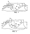
- FIG. 1 illustrates a saw blade embodying the invention.
- the saw blade generally designated by the reference numeral 10, includes a cutting edge defined by a plurality of saw teeth 12, each tooth having a tip 14, a rake face 16, and a relief surface 18 extending from the tip in a direction opposite to the saw blade's cutting direction designated in FIG. 1 by arrow A.
- the teeth 12 are spaced along the cutting edge with the tip of one tooth and the tip of the next consecutively disposed tooth cooperating to define a pitch distance P.
- a curvilinear base surface 20 extends between the rake face 16 of one tooth 12 and the relief surface 18 of the next consecutive tooth. As shown in FIG. 1 , the base surface 20 is tangent to the rake face 16.
- the rake face 16, the curvilinear base surface 20, and the relief surface 18 cooperate to define a gullet area 22.
- an effective gullet radius R eff is defined by the rake face 16 and the curvilinear base surface 20.
- R eff is equal to the horizontal distance from the leftmost point of the gullet area 22, when the saw blade 10 is viewed in the orientation shown in FIG. 1 , to the point where the gullet depth or gullet depth H reaches its maximum value.
- the relief surface 18 includes a primary relief surface 24 extending from the tip 14 of the tooth 12 and a secondary relief surface 26 extending from the primary relief surface tangent to a radius R 1 defined by the curvilinear base surface 20.
- the primary and secondary relief surfaces, 24 and 26, respectively, are further defined by first and second relief angles, ⁇ 1 and ⁇ 2 , respectively, measured from a plane extending parallel to the cutting direction A of the saw blade 10.
- the second relief angle ⁇ 2 is larger that the first relief angle ⁇ 1 , thereby increasing the size of the gullet area 22 over that which would be possible if only the first relief surface were present.
- the effective gullet radius R eff is equal to 30% of the pitch distance P.
- the effective gullet radius R eff is between 65% and 85% of the gullet depth, and preferably equal to about 81 % of the gullet depth.
- the length of the rake face 16 between the tip 14 of the tooth 12 and the point where the rake face is tangent to a radius R 2 defined by the curvilinear base surface 20, is preferably less than 25% of the gullet depth. This relatively short rake face length allows the radius R 2 to be maximized, thereby minimizing stress at the base of the tooth.
- a second embodiment of the saw blade of the present invention, shown in FIG. 2 is generally designated by the reference numeral 110.
- the saw blade 110 is similar in many respects to the saw blade 10 described above, and therefore like reference numerals preceded by the number 1 are used to indicate like elements.
- the saw blade 110 differs from the saw blade 10 in that the effective gullet radius R eff is approximately 36% of the pitch distance P and approximately 77% of the gullet depth H. In addition, the gullet depth is approximately 46% of the pitch distance P.
- the relief surface 118 includes a primary relief surface 124 extending from the tip 114 of the tooth 112, and a secondary relief surface 126 extending from the primary relief surface tangent to the radius R 101 defined by the curvilinear base surface 120.
- the primary and secondary relief surfaces, 124 and 126 are further defined by first and second relief angles, ⁇ 101 and ⁇ 102 , respectively, measured from a plane extending parallel to the cutting direction of the saw blade 110.
- the second relief angle ⁇ 102 is larger than the first relief angle ⁇ 101 .
- ⁇ 101 is approximately 35°
- ⁇ 102 is approximately 45°.
- FIG. 3 A third embodiment of the saw blade of the present invention is shown in FIG. 3 and is generally designated by the reference number 210.
- the saw blade 210 is similar in many respects to the saw blade 10 described above, and therefore like reference numerals preceded by the number 2 are used to indicate like elements.
- the saw blade 210 differs from the saw blade 10 in that the effective gullet radius R eff is approximately 41% of the pitch distance P and approximately 79% of the pullet depth H. In addition, the gullet depth is approximately 46% of the pitch distance.
- the relief surface 218 includes a primary relief surface 224 extending from the tip 214 of the tooth 212, and a secondary relief surface 226 extending from the primary relief surface tangent to the radius R 201 defined by the curvilinear base surface 220.
- the primary and secondary relief surfaces, 224 and 226, are further defined by first and second relief angles, ⁇ 201 and ⁇ 202, respectively, measured from a plane extending parallel to the cutting direction of the saw blade 210.
- the second relief angle ⁇ 202 is larger than the first relief angle ⁇ 201 . In the illustrated embodiment ⁇ 201 is approximately 35°, and ⁇ 202 is approximately 55°.
- a fourth embodiment of the saw blade of the present invention is shown in FIG. 4 and is generally designated by the reference numeral 310.
- the saw blade 310 is similar in many respects to the saw blade 10 described above, and therefore like reference numerals preceded by the number 3 are used to indicate like elements.
- the saw blade 310 differs from the saw blade 10 in that the rake face 316 defines a positive rake angle ⁇ rake measured from a plane extending approximately perpendicular to the cutting direction A of the saw blade 310. While the angle ⁇ rake is positive in the illustrated embodiment, the present invention is not limited in this regard as ⁇ rake can also be zero or negative without departing from the broader aspects of the invention.
- the embodiment illustrated in FIG. 4 also differs from the other embodiments described above in that the curvilinear base surface 320 is defined by a combination of radii, R 301 and R 302, with rectilinear portion L 301 interposed therebetween.
- the relief surface 318 includes a primary relief surface 324 defined by relief angle ⁇ 301, and a secondary relief surface 326 defined by radius R 303.
- the radius R 303 is tangent to the primary relief surface 324 and the radius R 301 defined by the curvilinear base surface 320.
- the radius R 303 is convex relative to the radius R 301 defined by the curvilinear base surface 320.
- the invention is not limited in this regard as the radius R 303 does not have to be tangent to the primary relief surface 324 or the curvilinear base surface 320.
- the curvilinear base surface 320 has been shown and described as being defined by a combination of radii, R 301 and R 302' with rectilinear portion L 301 interposed therebetween, the present invention is not limited in this regard.
- the curvilinear base surface 320 can be defined by any combination of radii and rectilinear sections without departing from the broader aspects of the present invention.
- the relief surface 318 while shown and described in the illustrated embodiment as including a rectilinear primary relief surface 324 and a radial secondary relief surface 326, is not limited in this regard as any combination of radial and rectilinear surfaces can be employed without departing from the broader aspects of the present invention.
- chips are generated by the saw blades, 110, 210, or 310, which flow into the respective gullet areas. As the cutting operation continues, the chips must be discharged from the gullet areas so that newly generated chips can be accommodated.
- the larger gullet areas provide the saw blades with the capability to handle larger volumes of chips, thereby enabling the blades to operate at higher speeds.
- the large radii which define the curvilinear base surfaces provide the teeth of these blades with enhanced stress-bearing capabilities by minimizing any stress concentrations at the base of the teeth. This in turn reduces the likelihood of the teeth shearing or tearing from the blades, thereby enabling them to cut materials at higher speeds which would normally impose large amounts of stress on the teeth.
Landscapes
- Engineering & Computer Science (AREA)
- Mechanical Engineering (AREA)
- Milling Processes (AREA)
- Knives (AREA)
- Processing Of Stones Or Stones Resemblance Materials (AREA)
- Drilling Tools (AREA)
- Perforating, Stamping-Out Or Severing By Means Other Than Cutting (AREA)
Abstract
Description
- The present invention relates generally to saw blades, and deals more particularly with an improved tooth form for providing enhanced discharge of chips from the gullet area of each tooth and improved tooth strength. The present invention relates to a saw blade according to the preamble of claim 1. Such a saw blade is known from
US 4292871 . - The terms used herein to describe the profile of a saw blade tooth are to be construed in accordance with the definitions found in International Standard Number ISO 4875/1-1978. In addition, the phrase "effective gullet radius" as used herein should be construed to mean the horizontal distance from the leftmost point of the gullet area, when the saw blade is viewed with the teeth pointing upward, to the point where the gullet depth reaches its maximum value.
- In many instances, particularly in production settings, it is desirable to cut materials such as wood, plastic, and metal at the highest feed rates achievable. However, the rate at which a particular material can be presented to the saw blade is governed in large part by the stresses induced in the teeth of the blade, as well as by the rate at which particles or chips generated by the cutting action of the blade are discharged from the gullet area between consecutively spaced teeth.
- In prior art tooth forms, the effective gullet radius is relatively small, typically less than approximately 25% of the tooth pitch. In addition, the gullet depth is typically between about 40% and about 50% of the tooth pitch with the length of the rake face accounting for approximately half of the height. As a result of this relatively small effective gullet radius and the relatively long rake face, shear stresses are concentrated at the base of each tooth on the saw blade which often are of sufficient magnitude to tear or shear a tooth from the saw blade during a cutting operation.
- Another problem associated with known tooth forms having a profile similar to that described above is that during a cutting operation, the long rake face combined with a small gullet radius inhibits the flow of chips out of the gullet area by acting as a barrier. This creates the potential for the chips generated during a cutting operation to become lodged in the gullet area, which in turn diminishes the cutting efficiency of the saw blade. To minimize this problem, the feed rate of the material through the saw, or the cutting speed of the blade, must be reduced, resulting in a concomitant reduction in production.
- Based on the foregoing, it is the general object of the present invention to provide a saw blade employing a tooth profile that overcomes the above-described drawbacks of prior art saw blade teeth.
- It is a more specific object of the present invention to provide a saw tooth profile having enhanced chip discharge characteristics.
- These objects are achieved by a saw blade having the combination of features of claim 1.
-
-
FIG. 1 is an enlarged partial side elevational view of the saw blade of the present invention; -
FIG. 2 is an enlarged partial side elevational view of an alternate embodiment of the saw blade ofFIG. 1 ; -
FIG. 3 is an enlarged partial side elevational view of an alternate embodiment of the saw blade ofFIG. 1 ; and -
FIG. 4 is an enlarged partial side elevational view of an alternate embodiment of the saw blade ofFIG. 1 . -
FIG. 1 illustrates a saw blade embodying the invention. The saw blade, generally designated by thereference numeral 10, includes a cutting edge defined by a plurality ofsaw teeth 12, each tooth having atip 14, arake face 16, and arelief surface 18 extending from the tip in a direction opposite to the saw blade's cutting direction designated inFIG. 1 by arrow A. Theteeth 12 are spaced along the cutting edge with the tip of one tooth and the tip of the next consecutively disposed tooth cooperating to define a pitch distance P. Acurvilinear base surface 20 extends between therake face 16 of onetooth 12 and therelief surface 18 of the next consecutive tooth. As shown inFIG. 1 , thebase surface 20 is tangent to therake face 16. The rake face 16, thecurvilinear base surface 20, and therelief surface 18 cooperate to define agullet area 22. In addition, an effective gullet radius Reff is defined by therake face 16 and thecurvilinear base surface 20. Reff is equal to the horizontal distance from the leftmost point of thegullet area 22, when thesaw blade 10 is viewed in the orientation shown inFIG. 1 , to the point where the gullet depth or gullet depth H reaches its maximum value. - Still referring to
FIG. 1 , therelief surface 18 includes aprimary relief surface 24 extending from thetip 14 of thetooth 12 and asecondary relief surface 26 extending from the primary relief surface tangent to a radius R 1 defined by thecurvilinear base surface 20. The primary and secondary relief surfaces, 24 and 26, respectively, are further defined by first and second relief angles, θ1 and θ2, respectively, measured from a plane extending parallel to the cutting direction A of thesaw blade 10. The second relief angle θ2 is larger that the first relief angle θ1, thereby increasing the size of thegullet area 22 over that which would be possible if only the first relief surface were present. - In the embodiment of the present invention illustrated in
FIG. 1 , the effective gullet radius Reff is equal to 30% of the pitch distance P. In addition, the effective gullet radius Reff is between 65% and 85% of the gullet depth, and preferably equal to about 81 % of the gullet depth. Moreover, the length of therake face 16 between thetip 14 of thetooth 12 and the point where the rake face is tangent to a radius R 2 defined by thecurvilinear base surface 20, is preferably less than 25% of the gullet depth. This relatively short rake face length allows the radius R 2 to be maximized, thereby minimizing stress at the base of the tooth. - Still referring to
FIG. 1 , during a cutting operation, chips generated by thesaw blade 10 flow into thegullet areas 22 between consecutively disposedteeth 12. As the cutting operation continues, the chips must be discharged from thegullet areas 22 so that newly generated chips can be accommodated. The large effective gullet radius Reff, the relativelyshort rake face 16, the primary and secondary relief surfaces, 24 and 26, respectively, and thecurvilinear base surface 20 all cooperate to define agullet area 22 that provides for the smooth ingress and egress of chips to and from the gullet area. - A second embodiment of the saw blade of the present invention, shown in
FIG. 2 , is generally designated by thereference numeral 110. Thesaw blade 110 is similar in many respects to thesaw blade 10 described above, and therefore like reference numerals preceded by the number 1 are used to indicate like elements. Thesaw blade 110 differs from thesaw blade 10 in that the effective gullet radius Reff is approximately 36% of the pitch distance P and approximately 77% of the gullet depth H. In addition, the gullet depth is approximately 46% of the pitch distance P. - Still referring to
FIG. 2 , therelief surface 118 includes aprimary relief surface 124 extending from thetip 114 of thetooth 112, and asecondary relief surface 126 extending from the primary relief surface tangent to the radius R101 defined by thecurvilinear base surface 120. The primary and secondary relief surfaces, 124 and 126, are further defined by first and second relief angles, θ101 and θ102, respectively, measured from a plane extending parallel to the cutting direction of thesaw blade 110. The second relief angle θ102 is larger than the first relief angle θ101. In the illustrated embodiment θ101 is approximately 35°, and θ102 is approximately 45°. - A third embodiment of the saw blade of the present invention is shown in
FIG. 3 and is generally designated by thereference number 210. Thesaw blade 210 is similar in many respects to thesaw blade 10 described above, and therefore like reference numerals preceded by the number 2 are used to indicate like elements. Thesaw blade 210 differs from thesaw blade 10 in that the effective gullet radius Reff is approximately 41% of the pitch distance P and approximately 79% of the pullet depth H. In addition, the gullet depth is approximately 46% of the pitch distance. - The
relief surface 218 includes aprimary relief surface 224 extending from thetip 214 of thetooth 212, and asecondary relief surface 226 extending from the primary relief surface tangent to the radius R201 defined by thecurvilinear base surface 220. The primary and secondary relief surfaces, 224 and 226, are further defined by first and second relief angles, θ201 and θ202, respectively, measured from a plane extending parallel to the cutting direction of thesaw blade 210. The second relief angle θ202 is larger than the first relief angle θ201. In the illustrated embodiment θ201 is approximately 35°, and θ202 is approximately 55°. - A fourth embodiment of the saw blade of the present invention is shown in
FIG. 4 and is generally designated by thereference numeral 310. Thesaw blade 310 is similar in many respects to thesaw blade 10 described above, and therefore like reference numerals preceded by the number 3 are used to indicate like elements. Thesaw blade 310 differs from thesaw blade 10 in that therake face 316 defines a positive rake angle θrake measured from a plane extending approximately perpendicular to the cutting direction A of thesaw blade 310. While the angle θrake is positive in the illustrated embodiment, the present invention is not limited in this regard as θrake can also be zero or negative without departing from the broader aspects of the invention. - The embodiment illustrated in
FIG. 4 also differs from the other embodiments described above in that thecurvilinear base surface 320 is defined by a combination of radii, R 301 and R 302, with rectilinear portion L 301 interposed therebetween. In addition, therelief surface 318 includes aprimary relief surface 324 defined by relief angle θ301, and asecondary relief surface 326 defined by radius R 303. In the illustrated embodiment, the radius R 303 is tangent to theprimary relief surface 324 and the radius R 301 defined by thecurvilinear base surface 320. In addition, the radius R 303 is convex relative to the radius R 301 defined by thecurvilinear base surface 320. However, the invention is not limited in this regard as the radius R 303 does not have to be tangent to theprimary relief surface 324 or thecurvilinear base surface 320. In addition, while thecurvilinear base surface 320 has been shown and described as being defined by a combination of radii, R 301 and R 302' with rectilinear portion L 301 interposed therebetween, the present invention is not limited in this regard. Thecurvilinear base surface 320 can be defined by any combination of radii and rectilinear sections without departing from the broader aspects of the present invention. Moreover, therelief surface 318, while shown and described in the illustrated embodiment as including a rectilinearprimary relief surface 324 and a radialsecondary relief surface 326, is not limited in this regard as any combination of radial and rectilinear surfaces can be employed without departing from the broader aspects of the present invention. - Referring to
FIGS. 2-4 , during a cutting operation, chips are generated by the saw blades, 110, 210, or 310, which flow into the respective gullet areas. As the cutting operation continues, the chips must be discharged from the gullet areas so that newly generated chips can be accommodated. The larger effective gullet radii R eff' the relatively short rake faces, the larger angles or radii of thesecondary relief surfaces - While preferred embodiments have been shown and described, various modifications and substitutions may be made without departing from the scope of the present invention.
Claims (10)
- A saw blade (10, 110, 210, 310) having a cutting edge defined by a plurality of teeth (12, 112, 212) disposed along the blade, each of said teeth (12, 112, 212) having a tip (14, 114, 214), a rake face (16, 316) adjacent to the tip (14, 114, 214), a curvilinear base surface (20, 120, 220, 320) located on an opposite side of the rake face (16, 316) relative to the tip (14, 114, 214), and a relief surface (18, 118, 218, 318) located on an opposite side of the tip (14, 114, 214) relative to the rake face (16, 316), the tip (14, 114, 214) of each tooth and the tip (14, 114, 214) of the next consecutively disposed tooth defining a pitch (P) distance, and the curvilinear base surface (20, 120, 220, 320) and the tip (14, 114, 214) of each tooth cooperating to define a maximum gullet depth (H), wherein the rake face (16, 316) and the curvilinear base surface (20, 120, 220, 320) of each tooth cooperate to define an effective gullet radius (R eff ) defined by the horizontal distance from the leftmost point of the gullet area (22, 122, 222), when the saw blade (10, 110, 210, 310) is viewed with the teeth (12, 112, 212) pointing upward, to the point where the gullet depth (H) reaches its maximum value wherein the relief surface (18, 118, 218) of each tooth includes a primary relief surface (24, 124, 224) located on an opposite side of the tip (14, 114, 214) relative to the rake face (16), and a secondary relief surface (26, 126, 226) located on an opposite side of the primary relief surface (24, 124, 224) relative to the tip (14, 114, 214) the primary relief surface (24, 124, 224) being defined by a first acute relief angle (θ1, θ101, θ201) relative to a plane extending between the tips (14, 114, 214) of consecutively disposed teeth (12, 112, 212), and the secondary relief surface (26, 126, 226) being defined by a secondary relief angle (θ2,θ102, θ202) relative to said plane greater than the first relief angle (θ1, θ101, θ201,) and between 45 degrees and 55 degrees or wherein the relief surface of each tooth is defined by a primary relief surface (324) extending from the tip of the tooth, and a secondary relief surface (326) extending from the primary relief surface (324); and wherein a respective one of the primary (324) and secondary relief (326) surfaces is defined by a relief angle (θ301) measured from a plane parallel with the direction of cut (A) of the saw blade (310), and the other of the primary (324) and secondary relief (326) surfaces is convex defined by a radius (R303), and wherein the maximum gullet depth (H) is greater than 40% of the pitch (P) distance, characterized in that the effective gullet radius (R eff ) is between 65% and 85% of the maximum gullet depth (H) and at least 30% of the pitch (P) distance.
- The saw blade (310) of claim 1 wherein the rake face (316) of each tooth defines a positive rake angle (θrake).
- The saw blade (310) of claim 1 wherein the rake face (316) of each tooth defines a negative rake angle (θrake).
- The saw blade (10, 110, 210, 310) of claim 1 wherein the first relief angle (θ1 θ101,θ201, θ301) is 35 degrees.
- The saw blade (10, 110, 210, 310) of claim 4 wherein the second relief angle (θ2, θ102, θ202) is 45 degrees.
- The saw blade (10, 110, 210, 310) of claim 4 wherein the second relief angle (θ2,θ102,θ202) is 55 degrees.
- The saw blade (10, 110, 210, 310) according to any of the preceding claims, wherein the curvilinear base surface (20, 120, 220, 320) is defined by a first radius (R2, R102, R202, R302) tangent to the rake face (16, 316) and a second radius. (R1, R101, R201, R301) tangent at one end to the first radius (R2, R102, R202, R302).
- The saw blade (10, 110, 210, 310) according to any of the preceding claims, wherein the curvilinear base surface (20, 120, 220, 320) is defined by a first radius (R2, R102, R202, R302) tangent to the rake face (16, 316) and at least a second radius (R1, R101, R201, R301) tangent at one end to the first radius (R2, R102, R202, R302) and at another end to the at least one relief surface (18, 118, 218, 318).
- The saw blade (10, 110, 210, 310) according to any of the preceding claims, wherein the curvilinear base surface (20, 120, 220, 320) is defined by a combination of radial and rectilinear sections (R301, L301, R302).
- The saw blade (10, 110, 210, 310) according to any of claims 1-9, wherein the effective gullet radius (R eff ) is 77% of the maximum gullet depth (H) and the maximum gullet depth (H) is 46% of the pitch (P) distance.
Applications Claiming Priority (3)
| Application Number | Priority Date | Filing Date | Title |
|---|---|---|---|
| US15122 | 1993-02-09 | ||
| US09/015,122 US6167792B1 (en) | 1995-03-23 | 1998-01-29 | Tooth form for a saw blade |
| PCT/US1999/002113 WO1999038661A1 (en) | 1998-01-29 | 1999-01-29 | Improved tooth form for a saw blade |
Publications (3)
| Publication Number | Publication Date |
|---|---|
| EP1105265A1 EP1105265A1 (en) | 2001-06-13 |
| EP1105265A4 EP1105265A4 (en) | 2008-03-26 |
| EP1105265B1 true EP1105265B1 (en) | 2011-10-26 |
Family
ID=21769645
Family Applications (1)
| Application Number | Title | Priority Date | Filing Date |
|---|---|---|---|
| EP99904503A Revoked EP1105265B1 (en) | 1998-01-29 | 1999-01-29 | Improved tooth form for a saw blade |
Country Status (6)
| Country | Link |
|---|---|
| US (1) | US6167792B1 (en) |
| EP (1) | EP1105265B1 (en) |
| JP (1) | JP4139876B2 (en) |
| AU (1) | AU2488999A (en) |
| CA (1) | CA2320904C (en) |
| WO (1) | WO1999038661A1 (en) |
Cited By (1)
| Publication number | Priority date | Publication date | Assignee | Title |
|---|---|---|---|---|
| US9527146B2 (en) | 2013-10-04 | 2016-12-27 | Toronto Saw Works Inc. | Oscillating saw blades |
Families Citing this family (52)
| Publication number | Priority date | Publication date | Assignee | Title |
|---|---|---|---|---|
| US6439094B1 (en) * | 1997-05-15 | 2002-08-27 | Amada Company, Limited | Saw blade |
| JP2001062629A (en) * | 1999-06-22 | 2001-03-13 | Amada Co Ltd | Saw blade |
| EP1318218B1 (en) * | 1999-11-10 | 2005-03-23 | Graf + Cie Ag | Saw-toothed wire |
| US6601495B2 (en) * | 2000-07-18 | 2003-08-05 | American Saw & Mfg. Co., Inc. | Structural saw blade |
| DE10047212A1 (en) * | 2000-09-23 | 2002-04-11 | C & E Fein Gmbh & Co Kg | sawblade |
| US6588992B2 (en) * | 2001-02-06 | 2003-07-08 | Black & Decker Inc. | Hole saw |
| US7178441B2 (en) * | 2002-12-20 | 2007-02-20 | Kapman Ab | Versatile bandsaw blade |
| USD492170S1 (en) | 2003-02-20 | 2004-06-29 | Claude Auger | Saw tooth for radial saw blade |
| US6939092B2 (en) * | 2003-06-18 | 2005-09-06 | Irwin Industrial Tool Company | Sheet metal hole cutter |
| US7131365B2 (en) * | 2003-09-16 | 2006-11-07 | Irwin Industrial Tool Company | Multi-chip facet cutting saw blade and related method |
| RU2004101704A (en) * | 2004-01-20 | 2005-06-27 | Михаил Андреевич Бранфилев (RU) | ROUND CUTTING SAW |
| AU2005231308A1 (en) * | 2004-03-26 | 2005-10-20 | Black & Decker Inc. | Tooth form design for reciprocating saw blade |
| US7225714B2 (en) * | 2004-12-22 | 2007-06-05 | Black & Decker Inc. | Tooth form design for reciprocating saw blade |
| US7658136B2 (en) * | 2004-12-22 | 2010-02-09 | Black & Decker Inc. | Hole saw blade |
| US20050211046A1 (en) * | 2004-03-26 | 2005-09-29 | Thomas Rickey J | Tooth form design for reciprocating saw blade |
| US7174823B2 (en) * | 2004-09-22 | 2007-02-13 | Irwin Industrial Tool Company | Saw blade having increased tooth stiffness and resistance to fatigue failure |
| US20090199693A1 (en) * | 2005-04-20 | 2009-08-13 | Saint-Gobain Abrasives, Inc. | Circular Saw Blade With Elliptical Gullets |
| US7946907B2 (en) * | 2005-04-20 | 2011-05-24 | Saint-Gobain Abrasives, Inc. | Saw blade gullet configuration |
| US7264428B2 (en) * | 2005-05-19 | 2007-09-04 | Irwin Industrial Tool Company | Hole saw and cutter |
| US20080022832A1 (en) * | 2006-07-27 | 2008-01-31 | Black & Decker Inc. | Saw blade for cutting cement board |
| JP5428096B2 (en) * | 2006-11-24 | 2014-02-26 | エリコン・トレーディング・アクチェンゲゼルシャフト,トリュープバッハ | Band saw and method of manufacturing a band saw |
| US8210081B2 (en) * | 2007-06-12 | 2012-07-03 | Irwin Industrial Tool Company | Reciprocating saw blade having variable-height teeth and related method |
| AU2009206492B2 (en) * | 2008-01-22 | 2011-04-28 | Saint-Gobain Abrasifs | Circular saw blade with offset gullets |
| RU2010140369A (en) * | 2008-03-04 | 2012-04-10 | Ирвин Индастриал Тул Компани (Us) | TOOLS HAVING WORKING SURFACES FROM SEALED POWDER METAL AND METHOD |
| US8826790B2 (en) * | 2008-07-09 | 2014-09-09 | The L.S. Starrett Company | Saw blade |
| DE102008045733B4 (en) * | 2008-09-04 | 2010-11-04 | J.N. Eberle & Cie Gmbh | Bandsaw blade with knob-like bulges |
| JP5508531B2 (en) * | 2009-07-27 | 2014-06-04 | アーウィン インダストリアル トゥール カンパニー | Saw blade and related method according to a pitch pattern including a single level sharpening pattern and a multilevel sharpening pattern |
| US10189099B2 (en) | 2010-04-22 | 2019-01-29 | Milwaukee Electric Tool Corporation | Saw Blade |
| EP2564966B1 (en) | 2010-04-22 | 2017-04-12 | Milwaukee Electric Tool Corporation | Saw blade |
| US9375796B2 (en) * | 2010-05-07 | 2016-06-28 | Irwin Industrial Tool Company | Saw blade with robust tooth form |
| USD642028S1 (en) | 2010-05-21 | 2011-07-26 | Irwin Industrial Tool Company | Reciprocating saw blade |
| US9248518B2 (en) | 2010-06-30 | 2016-02-02 | Irwin Industrial Tool Company | Saw blade tooth form for abusive cutting applications |
| CA2749666C (en) | 2010-08-20 | 2014-07-15 | Milwaukee Electric Tool Corporation | Reciprocating saw blade |
| EP2442115B1 (en) | 2010-10-18 | 2013-04-10 | Milwaukee Electric Tool Corporation | Clamp meter with detachable clamp and clamp storage area |
| USD841417S1 (en) | 2011-04-22 | 2019-02-26 | Milwaukee Electric Tool Corporation | Saw blade |
| US9731365B2 (en) * | 2011-12-07 | 2017-08-15 | Irwin Industrial Tool Company | Saw blade with tooth form projection |
| CN102581382A (en) * | 2012-03-22 | 2012-07-18 | 重庆锐能五金工具有限公司 | Iron-cutting ultrathin alloy saw blade for machine tool |
| DE102012205041A1 (en) * | 2012-03-29 | 2013-10-02 | Robert Bosch Gmbh | Sawing tool for a machine tool |
| SE536576C2 (en) * | 2012-06-29 | 2014-03-04 | Munkforssaagar Ab | Bread knife blade and method for its manufacture |
| WO2014015163A1 (en) | 2012-07-18 | 2014-01-23 | Milwaukee Electric Tool Corporation | Toothform for a cutting tool, such as a hole saw |
| WO2014015154A1 (en) | 2012-07-18 | 2014-01-23 | Milwaukee Electric Tool Corporation | Hole saw |
| US10906111B2 (en) | 2013-07-29 | 2021-02-02 | The M.K. Morse Company | Method of using a cutting blade |
| ITUD20130133A1 (en) * | 2013-10-16 | 2015-04-17 | Gi Esse Salvador S R L | "CUTTING TAPE FOR CUTTING BONES OR MEAT WITH BONES OR MEAT" |
| US9782840B2 (en) | 2014-07-01 | 2017-10-10 | James Edwin Funk | Safety drilling tool |
| DE102016114622A1 (en) * | 2016-08-08 | 2018-02-08 | TRüTZSCHLER GMBH & CO. KG | sawtooth |
| US10166612B2 (en) | 2016-08-26 | 2019-01-01 | Irwin Industrial Tool Company | Tooth formations and arrangement for a saw blade |
| US9975192B2 (en) * | 2016-08-30 | 2018-05-22 | Simonds International L.L.C. | Systems and methods for milling saw blade tooth profiles and saw blades with milled tooth profiles |
| CN120921474A (en) | 2017-05-16 | 2025-11-11 | 米沃奇电动工具公司 | Saw blade |
| US10537951B2 (en) | 2017-08-16 | 2020-01-21 | Black & Decker Inc. | Band saw blade for cutting structural workpieces |
| WO2020014340A1 (en) | 2018-07-10 | 2020-01-16 | Milwaukee Electric Tool Corporation | Hole saw with hex sidewall holes |
| WO2020257303A1 (en) | 2019-06-20 | 2020-12-24 | Milwaukee Electric Tool Corporation | Hole saw with circular sidewall openings |
| USD958855S1 (en) | 2019-12-09 | 2022-07-26 | Milwaukee Electric Tool Corporation | Hole saw |
Family Cites Families (20)
| Publication number | Priority date | Publication date | Assignee | Title |
|---|---|---|---|---|
| US167882A (en) * | 1875-09-21 | Improvement in modes of inserting diamonds into saws for sawing stone | ||
| US142781A (en) * | 1873-09-16 | Improvement in saw-teeth | ||
| US2757697A (en) * | 1950-06-07 | 1956-08-07 | Simmons | Slicing blade or band |
| US3072164A (en) * | 1959-12-28 | 1963-01-08 | Southern Saw Service Inc | Saw blade |
| GB1022453A (en) * | 1964-03-16 | 1966-03-16 | Samuel Fox & Company Ltd | Improvements in metal cutting saws |
| SE315102B (en) * | 1967-09-22 | 1969-09-22 | O Ohlsson | |
| PL79090B1 (en) * | 1972-09-19 | 1975-06-30 | ||
| US4012820A (en) * | 1975-06-16 | 1977-03-22 | The Motch & Merryweather Machinery Company | Circular saw having teeth with an improved metal breaking geometry |
| US4179967A (en) * | 1978-08-28 | 1979-12-25 | Stanadyne, Inc. | Variable tooth saw blade |
| US4292871A (en) | 1979-02-01 | 1981-10-06 | The L. S. Starrett Company | Welded edge band saw tooth geometry |
| US4232578A (en) * | 1979-07-09 | 1980-11-11 | Wallace Murray Corporation | Saw blade and method of making |
| CH660326A5 (en) * | 1983-01-13 | 1987-04-15 | Tecno Zuerich Ag | SAW BLADE FOR THE PROCESSING OF WOOD OR SIMILAR MATERIALS. |
| DE3307170C2 (en) * | 1983-03-01 | 1986-08-14 | Wilhelm H. Kullmann WIKUS-Sägenfabrik, 3509 Spangenberg | Saw blade and process for its manufacture |
| JP2616924B2 (en) | 1987-07-02 | 1997-06-04 | 株式会社 アマダ | Saw blade |
| US5018421A (en) | 1988-04-07 | 1991-05-28 | Armstrong-Blum Manufacturing Company, Ltd. | Saw blade tooth geometry |
| US5249485A (en) | 1991-12-31 | 1993-10-05 | Sandvik Ab | Bandsaw blade and method of manufacturing same |
| US5331876A (en) * | 1992-07-30 | 1994-07-26 | Sandvik Ab | Saw blade for cutting metal |
| DE4308596A1 (en) * | 1992-08-13 | 1994-02-17 | Sandvik Ab | Segment plate for a saw blade and saw blade with segment plates |
| DE69535770D1 (en) * | 1994-08-19 | 2008-07-31 | Black & Decker Inc | SAW DENTAL FORM AND METHOD FOR THE PRODUCTION THEREOF |
| US5501129A (en) | 1994-09-27 | 1996-03-26 | Armstrong-Blum Manufacturing Company | All purpose saw blade |
-
1998
- 1998-01-29 US US09/015,122 patent/US6167792B1/en not_active Expired - Lifetime
-
1999
- 1999-01-29 EP EP99904503A patent/EP1105265B1/en not_active Revoked
- 1999-01-29 JP JP2000529934A patent/JP4139876B2/en not_active Expired - Fee Related
- 1999-01-29 AU AU24889/99A patent/AU2488999A/en not_active Abandoned
- 1999-01-29 CA CA002320904A patent/CA2320904C/en not_active Expired - Lifetime
- 1999-01-29 WO PCT/US1999/002113 patent/WO1999038661A1/en not_active Ceased
Cited By (1)
| Publication number | Priority date | Publication date | Assignee | Title |
|---|---|---|---|---|
| US9527146B2 (en) | 2013-10-04 | 2016-12-27 | Toronto Saw Works Inc. | Oscillating saw blades |
Also Published As
| Publication number | Publication date |
|---|---|
| WO1999038661A1 (en) | 1999-08-05 |
| JP4139876B2 (en) | 2008-08-27 |
| CA2320904A1 (en) | 1999-08-05 |
| CA2320904C (en) | 2005-10-11 |
| US6167792B1 (en) | 2001-01-02 |
| AU2488999A (en) | 1999-08-16 |
| JP2002501841A (en) | 2002-01-22 |
| EP1105265A4 (en) | 2008-03-26 |
| EP1105265A1 (en) | 2001-06-13 |
Similar Documents
| Publication | Publication Date | Title |
|---|---|---|
| US6167792B1 (en) | Tooth form for a saw blade | |
| US11203072B2 (en) | Tooth formations and arrangement for a saw blade | |
| US5832803A (en) | Tooth structure of a bandsaw blade | |
| US4557172A (en) | Saw blade | |
| US5603252A (en) | Saw blade | |
| US5331876A (en) | Saw blade for cutting metal | |
| US5868058A (en) | Log mill band-saw blade for initial processing of timber and derivatives thereof | |
| US20110033251A1 (en) | Rotary cutting tool with reverse chipbreaker pattern | |
| US6257226B1 (en) | Metal-cutting saw having straight and set teeth and method of making | |
| KR20110126113A (en) | Rotary cutting tool with chip breaker pattern | |
| US20010015120A1 (en) | Bandsaw blade having set teeth and exhibiting reduced lateral force | |
| US6314854B1 (en) | Saw blades with convex ground saw tooth flanks | |
| US12377481B2 (en) | Saw blade including a cutting tooth with a protrusion | |
| US7178441B2 (en) | Versatile bandsaw blade | |
| CN1151710A (en) | cutting insert | |
| US4102231A (en) | Circular saw blades | |
| US8714059B2 (en) | Saw blade with single level and multiple level set patterns within pitch patterns, and related method | |
| JP5102203B2 (en) | Reamer with cutting plate | |
| EP0849022B1 (en) | Saw blade comprising recurring groups of teeth | |
| JP2005349512A (en) | Saw blade | |
| JPH0349822A (en) | Band saw and cutting method of metal material used thereof | |
| JPH10100013A (en) | Cutting inserts and cutting tools |
Legal Events
| Date | Code | Title | Description |
|---|---|---|---|
| PUAI | Public reference made under article 153(3) epc to a published international application that has entered the european phase |
Free format text: ORIGINAL CODE: 0009012 |
|
| 17P | Request for examination filed |
Effective date: 20000721 |
|
| AK | Designated contracting states |
Kind code of ref document: A1 Designated state(s): DE DK FR GB IT SE |
|
| A4 | Supplementary search report drawn up and despatched |
Effective date: 20080227 |
|
| 17Q | First examination report despatched |
Effective date: 20080917 |
|
| GRAP | Despatch of communication of intention to grant a patent |
Free format text: ORIGINAL CODE: EPIDOSNIGR1 |
|
| GRAS | Grant fee paid |
Free format text: ORIGINAL CODE: EPIDOSNIGR3 |
|
| GRAA | (expected) grant |
Free format text: ORIGINAL CODE: 0009210 |
|
| AK | Designated contracting states |
Kind code of ref document: B1 Designated state(s): DE DK FR GB IT SE |
|
| REG | Reference to a national code |
Ref country code: GB Ref legal event code: FG4D |
|
| REG | Reference to a national code |
Ref country code: DE Ref legal event code: R096 Ref document number: 69943814 Country of ref document: DE Effective date: 20111222 |
|
| PG25 | Lapsed in a contracting state [announced via postgrant information from national office to epo] |
Ref country code: SE Free format text: LAPSE BECAUSE OF FAILURE TO SUBMIT A TRANSLATION OF THE DESCRIPTION OR TO PAY THE FEE WITHIN THE PRESCRIBED TIME-LIMIT Effective date: 20111026 |
|
| PLBI | Opposition filed |
Free format text: ORIGINAL CODE: 0009260 |
|
| PG25 | Lapsed in a contracting state [announced via postgrant information from national office to epo] |
Ref country code: DK Free format text: LAPSE BECAUSE OF FAILURE TO SUBMIT A TRANSLATION OF THE DESCRIPTION OR TO PAY THE FEE WITHIN THE PRESCRIBED TIME-LIMIT Effective date: 20111026 |
|
| 26 | Opposition filed |
Opponent name: WIKUS-SAEGENFABRIK WILHELM H. KULLMANN GMBH & CO. Effective date: 20120725 |
|
| PG25 | Lapsed in a contracting state [announced via postgrant information from national office to epo] |
Ref country code: IT Free format text: LAPSE BECAUSE OF FAILURE TO SUBMIT A TRANSLATION OF THE DESCRIPTION OR TO PAY THE FEE WITHIN THE PRESCRIBED TIME-LIMIT Effective date: 20111026 |
|
| PLAX | Notice of opposition and request to file observation + time limit sent |
Free format text: ORIGINAL CODE: EPIDOSNOBS2 |
|
| REG | Reference to a national code |
Ref country code: DE Ref legal event code: R026 Ref document number: 69943814 Country of ref document: DE Effective date: 20120725 |
|
| PLAF | Information modified related to communication of a notice of opposition and request to file observations + time limit |
Free format text: ORIGINAL CODE: EPIDOSCOBS2 |
|
| PLBB | Reply of patent proprietor to notice(s) of opposition received |
Free format text: ORIGINAL CODE: EPIDOSNOBS3 |
|
| RAP2 | Party data changed (patent owner data changed or rights of a patent transferred) |
Owner name: IRWIN INDUSTRIAL TOOL COMPANY |
|
| REG | Reference to a national code |
Ref country code: DE Ref legal event code: R103 Ref document number: 69943814 Country of ref document: DE Ref country code: DE Ref legal event code: R064 Ref document number: 69943814 Country of ref document: DE |
|
| RDAF | Communication despatched that patent is revoked |
Free format text: ORIGINAL CODE: EPIDOSNREV1 |
|
| RDAG | Patent revoked |
Free format text: ORIGINAL CODE: 0009271 |
|
| STAA | Information on the status of an ep patent application or granted ep patent |
Free format text: STATUS: PATENT REVOKED |
|
| PGFP | Annual fee paid to national office [announced via postgrant information from national office to epo] |
Ref country code: DE Payment date: 20140129 Year of fee payment: 16 |
|
| 27W | Patent revoked |
Effective date: 20131205 |
|
| GBPR | Gb: patent revoked under art. 102 of the ep convention designating the uk as contracting state |
Effective date: 20131205 |
|
| PGFP | Annual fee paid to national office [announced via postgrant information from national office to epo] |
Ref country code: FR Payment date: 20140117 Year of fee payment: 16 |
|
| REG | Reference to a national code |
Ref country code: DE Ref legal event code: R107 Ref document number: 69943814 Country of ref document: DE Effective date: 20140612 |
|
| PGFP | Annual fee paid to national office [announced via postgrant information from national office to epo] |
Ref country code: GB Payment date: 20140127 Year of fee payment: 16 |