EP1104340B1 - Dual roller stencil applicator - Google Patents
Dual roller stencil applicator Download PDFInfo
- Publication number
- EP1104340B1 EP1104340B1 EP99943678A EP99943678A EP1104340B1 EP 1104340 B1 EP1104340 B1 EP 1104340B1 EP 99943678 A EP99943678 A EP 99943678A EP 99943678 A EP99943678 A EP 99943678A EP 1104340 B1 EP1104340 B1 EP 1104340B1
- Authority
- EP
- European Patent Office
- Prior art keywords
- roller
- applicator
- tire
- hub
- rollers
- Prior art date
- Legal status (The legal status is an assumption and is not a legal conclusion. Google has not performed a legal analysis and makes no representation as to the accuracy of the status listed.)
- Expired - Lifetime
Links
- 230000009977 dual effect Effects 0.000 title claims description 6
- 239000003973 paint Substances 0.000 claims description 12
- 239000007788 liquid Substances 0.000 claims description 4
- 230000013011 mating Effects 0.000 claims description 4
- 230000009969 flowable effect Effects 0.000 claims description 2
- 238000004140 cleaning Methods 0.000 description 2
- 230000000994 depressogenic effect Effects 0.000 description 2
- 239000006260 foam Substances 0.000 description 2
- 239000000463 material Substances 0.000 description 2
- 239000012858 resilient material Substances 0.000 description 2
- 239000011248 coating agent Substances 0.000 description 1
- 238000000576 coating method Methods 0.000 description 1
- 238000012986 modification Methods 0.000 description 1
- 230000004048 modification Effects 0.000 description 1
Images



Classifications
-
- B—PERFORMING OPERATIONS; TRANSPORTING
- B05—SPRAYING OR ATOMISING IN GENERAL; APPLYING FLUENT MATERIALS TO SURFACES, IN GENERAL
- B05C—APPARATUS FOR APPLYING FLUENT MATERIALS TO SURFACES, IN GENERAL
- B05C17/00—Hand tools or apparatus using hand held tools, for applying liquids or other fluent materials to, for spreading applied liquids or other fluent materials on, or for partially removing applied liquids or other fluent materials from, surfaces
- B05C17/02—Rollers ; Hand tools comprising coating rollers or coating endless belts
- B05C17/03—Rollers ; Hand tools comprising coating rollers or coating endless belts with feed system for supplying material from an external source or with a reservoir or container for liquid or other fluent material located in or on the hand tool outside the coating roller
- B05C17/035—Rollers ; Hand tools comprising coating rollers or coating endless belts with feed system for supplying material from an external source or with a reservoir or container for liquid or other fluent material located in or on the hand tool outside the coating roller direct or indirectly to the outer surface of the coating roller
- B05C17/0352—Rollers ; Hand tools comprising coating rollers or coating endless belts with feed system for supplying material from an external source or with a reservoir or container for liquid or other fluent material located in or on the hand tool outside the coating roller direct or indirectly to the outer surface of the coating roller indirectly, i.e. by using transfer means, e.g. pads, brushes, rollers or bands
- B05C17/0355—Rollers ; Hand tools comprising coating rollers or coating endless belts with feed system for supplying material from an external source or with a reservoir or container for liquid or other fluent material located in or on the hand tool outside the coating roller direct or indirectly to the outer surface of the coating roller indirectly, i.e. by using transfer means, e.g. pads, brushes, rollers or bands using transfer rollers
Definitions
- This invention relates to the field of specialty or decorating implements, more specifically, to the field of hand-held stencil applicators useful to apply a stencil pattern to a surface such as an interior wall.
- a dual roller stencil applicator comprising the pre-characterizing features of claim 1 is known.
- the problem of the invention is to provide an applicator of this kind which provides for distance between the rollers when the applicator is not in operation and for contact of the rollers with each other when the applicator is operated. Further, a drive means for the second roller is to be provided.
- Applicator 10 preferably has a generally cylindrical first roller 12 having an axis 14 and a porous outer surface 16 preferably made of open cell foam for receiving and storing a flowable liquid such as paint or other similar coating material.
- the roller 12 is particularly designed and intended to carry paint, it is sometimes referred to as an "inking" roller, by analogy to ink impression stencil applicators.
- Applicator 10 also preferably has a generally cylindrical second roller 18 having an axis 20 parallel to axis 14 and a raised stencil pattern 22 on its outer surface 24. At least the outer surface of roller 18 is preferably made of relatively firm rubber or a similar resilient material. It is to be understood that, for simplicity, certain of the views of the stencil roller 18 are shown in a simplified cylindrical outline 26 as may be seen in Figure 2, but that stencil roller 18 will always have a raised or embossed pattern 22 thereon. Although one pattern is illustrated in Figure 1, it is to be understood that the present invention is not limited to the pattern shown or to any particular class or group of patterns.
- Applicator 10 also preferably has a frame 28 carrying the first and second rollers 12, 18 while holding the axes 14,20 of the first and second rollers in parallel alignment.
- Frame 28 has a handle 30 suitable for grasping by an operator and a pair of arms 32, 34 extending from the handle to carry the rollers 12 and 18.
- applicator 10 has a means for urging the first and second rollers apart during paint loading, while permitting the outer surfaces of the first and second rollers to contact each other during operation so that liquid stored in the foam cover 16 of the first roller 12 is delivered to the raised stencil pattern 22 of the second roller 18.
- the raised pattern 22 is part of the outer surface 24 of die stencil roller 18.
- the means for urging the rollers 12 and 18 apart is a slide apparatus 36 having a slide member 38 and a spring 40 acting between the slide member 38 and the frame 28. More particularly, spring 40 acts between a raised projection 42 on arm 32 or 34 and a wall 44 at the end of a tunnel-like recess 46 in slide member 38.
- the slide apparatus 36 may also have a latch member 48 to releasably hold the slide member 38 in a position causing the outer surfaces 16, 24 of the first and second rollers 12, 18 to be held in contact with each other.
- the latch member 48 is operable to release the slide member 38 to enable the spring 40 to move the rollers apart for paint loading.
- the applicator 10 also preferably has means for completely releasing the stencil roller 18 from the remainder of the applicator 10, to enable changing the pattern to be applied by the applicator, and to ease cleaning of the various parts of the applicator 10.
- the means to completely release the stencil roller is preferably a catch member 50 which may be formed as part of the latch member 48, or may be a separate part. It is to be understood that the catch member 50 preferably is made up of two arms 52 which may be manually compressed toward each other to release the slide member 38 from the frame 28.
- the applicator 10 also preferably has a means for driving the stencil roller 18 in the form of a resilient tire 54 mounted on a hub 56 which is drivingly connected to the stencil roller 18 through a flange 58.
- the driving means 54,56 may be coupled to the right side (indicated as position 60) or the left side (indicated as position 62 in phantom) of the stencil roller 18.
- the drive means is positioned on the side (60 or 62) which has not yet had any stencil pattern applied to it, to avoid smearing or distorting the pattern.
- the dual position for the tire 54 also allows stencil patterns to be applied closer to an obstruction such as an inside comer of a wall than might otherwise be the case.
- the tire 54 is preferably formed of a resilient material somewhat softer than the material on the outer surface 24 of stencil roller 18, to allow the tire to compress and provide positive traction on the surface it contacts. Additionally, tire 54 has a plurality of circumferential segments 64 spaced apart from each other by radially relieved portions 66 to allow the tire 54 to partially collapse in a radial direction when the tire is urged against a surface to which a stencil pattern is to be applied. Additionally (and referring now most particularly to Figure 3), the tire 54 has radially inwardly projecting protrusions 68 and the hub 56 has radially inwardly projecting recesses 70 which interengage the protrusions 68 to prevent the tire 54 from circumferentially slipping on the hub 56.
- hub 56 also has a square cross-section, axially projecting protrusion 72 which is received in a mating cross-section recess 74 in flange 58 to transmit torque from the tire 54 to the stencil roller 18. It is to be understood that other non-circular cross-sections may be used. Furthermore, detent means 76 made up of a mating bump 78 and hollow 80 may be used to retain the hub 56 to the flange 58.
- screws 82 or other conventional fastening means may be used to secure the latch and catch member 48 to the arm 32 or 34 of frame 28.
- Member 48 preferably has a pushbutton 84 projecting through an aperture 86 in frame 28.
- a locking tab 88 projects through an aperture portion 90 and is received in an aperture 92 in slide member 38.
- the applicator is shown in an operating condition, where the first and second rollers are in contact with each other.
- the stencil roller 18 is placed against, e.g., a wall, after being indexed to the proper starting position if desired, using the index numbers 94 on the side of hub 56.
- tire 54 is sightly compressed on a dry (unstenciled) portion of the wall, to give traction.
- Applicator 10 is then moved along the wall, preferably in a direction perpendicular to the axis 14, to apply a stencil pattern to the wall, with the "inking" roller 12 resupplying paint to the raised portion 22 of the stencil roller 18.
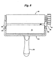
- pushbuttons 84 When it is necessary to replenish or reload the "inking" roller 12 with paint, pushbuttons 84 are depressed, releasing tabs 88 from recesses or apertures 92 in each slide member 38. Springs 40 will then move the stencil roller 18 away from roller 12, as shown most clearly in Figure 8. The operator may then reverse the grasp on handle 30 to invert the applicator 10 from the position shown in Figure 1, at which time the inking roller 12 may be rolled in a paint tray (not shown) to reload the applicator with paint.
Landscapes
- Engineering & Computer Science (AREA)
- Mechanical Engineering (AREA)
- Coating Apparatus (AREA)
Description
The problem of the invention is to provide an applicator of this kind which provides for distance between the rollers when the applicator is not in operation and for contact of the rollers with each other when the applicator is operated. Further, a drive means for the second roller is to be provided.
Claims (11)
- A dual roller stencil applicator comprising:a) a generally cylindrical first roller (12) having an axis (14) and a porous outer surface (16) for receiving and storing a flowable liquid paint;b) a generally cylindrical second roller (18) having an axis (20) and a stencil pattern (22) on an outer surface (24);c) a frame (28) holding the axes (14,20) of the first and second rollers (12,18) in parallel alignment; characterized byd) spring means (36,40) that urges the first and second rollers apart during loading and permits the outer surfaces (16, 24) of the first and second rollers to contact each other during operation such that the liquid paint stored in the porous outer surface of the first roller (12) is delivered to the raised stencil pattern of the second roller (18); ande) a resilient tire (54) adjacent and drivingly connected to the second roller (18) by frictional contact between the tire and a surface to which an image of the stencil pattern is to be applied.
- The applicator of claim 1, characterized in that the spring means (36,40) comprises a slide apparatus (36) mounted on the frame and a spring (40) that urges the rollers (12, 18) apart via the slide apparatus (36).
- The applicator of claim 2, characterized in that the slide apparatus (36) comprises a slide member (38) urged by the spring (40) acting between the slide member (38) and the frame (28) for urging the slide along the frame in a direction wherein the axes (14,20) of the first and second rollers (12,18) move apart.
- The applicator of one claims 1 to 3, characterized in that the tire (54) is carried by a hub (56) drivingly connected to the second roller (18).
- The applicator of one of claims 1 to 3, characterized in that the tire (54) comprises a plurality of circumferential segments (64) spaced apart from each other by radially relieved portions (66) to allow the tire to partially collapse in a radial direction when the tire is urged against a surface to which a stencil pattern is to be applied.
- The applicator of claim 4 or 5, characterized in that the hub (56) and tire (54) have at least one set of a radially directed interengaging protrusion (68) and recess (70) to prevent the tire from circumferentially slipping on the hub.
- The applicator of one of claims 4 to 6, characterized in that the hub and tire (56,54) for driving the second roller (18) is selectively connectable to the second roller at a first end thereof and is repositionable to drive the second roller at a second end thereof.
- The applicator of claim 7, characterized in that the hub (56) comprises a support flange (58) carrying the second roller (18) and non-circular protrusion (72) received in a recess (74) to transmit torque from the tire to the second roller, via the flange (58).
- The applicator of claim 8, characterized in that the mating non-circular protrusion (72) and recess (74) each have a square cross-section.
- The applicator of claim 8, characterized in that the mating non -circular protrusion (72) and recess (74) have detent means to retain the hub (56) to the flange (58).
- The applicator of one of claims 8 to 13, characterized in that the hub (56) projects through the slide apparatus (36) to engage the flange (58).
Applications Claiming Priority (3)
| Application Number | Priority Date | Filing Date | Title |
|---|---|---|---|
| US09/133,738 US5967041A (en) | 1998-08-13 | 1998-08-13 | Dual roller stencil applicator |
| US133738 | 1998-08-13 | ||
| PCT/US1999/018263 WO2000009272A1 (en) | 1998-08-13 | 1999-08-11 | Dual roller stencil applicator |
Publications (2)
| Publication Number | Publication Date |
|---|---|
| EP1104340A1 EP1104340A1 (en) | 2001-06-06 |
| EP1104340B1 true EP1104340B1 (en) | 2002-07-24 |
Family
ID=22460087
Family Applications (1)
| Application Number | Title | Priority Date | Filing Date |
|---|---|---|---|
| EP99943678A Expired - Lifetime EP1104340B1 (en) | 1998-08-13 | 1999-08-11 | Dual roller stencil applicator |
Country Status (5)
| Country | Link |
|---|---|
| US (1) | US5967041A (en) |
| EP (1) | EP1104340B1 (en) |
| AU (1) | AU5672899A (en) |
| DE (1) | DE69902279T2 (en) |
| WO (1) | WO2000009272A1 (en) |
Families Citing this family (9)
| Publication number | Priority date | Publication date | Assignee | Title |
|---|---|---|---|---|
| US20050150394A1 (en) * | 2002-08-28 | 2005-07-14 | Errera Richard B. | Food embossing and impressing device |
| US7367180B2 (en) * | 2004-03-05 | 2008-05-06 | Ford Global Technologies Llc | System and method for controlling valve timing of an engine with cylinder deactivation |
| US7600471B2 (en) | 2005-05-10 | 2009-10-13 | Westby Ronald K | Hand proofer tool |
| US20070143946A1 (en) * | 2005-12-27 | 2007-06-28 | Song Kim | Multi paint roller connector |
| US8720335B2 (en) * | 2007-04-24 | 2014-05-13 | Probity Engineering, Llc | Offset hand proofer tool |
| WO2010014619A2 (en) * | 2008-07-28 | 2010-02-04 | Integrity Engineering, Inc. | Improvements to flexographic proofing tools and methods |
| US8832897B2 (en) | 2009-10-29 | 2014-09-16 | Arigala Painting, Inc. | Dual-roller paint roller |
| CN111687013A (en) * | 2020-06-30 | 2020-09-22 | 张祖明 | Printing roller for wall decoration |
| CN113235873B (en) * | 2021-05-17 | 2023-02-03 | 中化学城市投资有限公司 | Paint roller brush capable of being replaced and coated conveniently |
Family Cites Families (11)
| Publication number | Priority date | Publication date | Assignee | Title |
|---|---|---|---|---|
| US2035127A (en) * | 1932-09-08 | 1936-03-24 | Francis J Hinton | Wall decorating device |
| CH246271A (en) * | 1945-06-13 | 1946-12-31 | Sigg Hans | Stamp. |
| US2611914A (en) * | 1949-11-18 | 1952-09-30 | Charles E Vanasse | Manually operated fluid applicator |
| DE847155C (en) * | 1950-04-22 | 1952-08-21 | Hans Schnaeckel | Roller stamp |
| DE924612C (en) * | 1951-09-21 | 1955-03-03 | Wilhelm Fleissner | Sample roller apparatus with sample and color transfer roller |
| US2805436A (en) * | 1954-08-02 | 1957-09-10 | Jerome J Christensen | Paint applicator |
| FR1236218A (en) * | 1959-09-08 | 1960-07-15 | Automatic feeding device for the rolls to be painted | |
| US4040350A (en) * | 1976-07-01 | 1977-08-09 | Diagraph-Bradley Industries, Inc. | Rotary printer |
| US4817526A (en) * | 1987-10-22 | 1989-04-04 | Winston Jeffrey M | Rolling contact printer with retractable inking wheel |
| US5495800A (en) * | 1995-03-29 | 1996-03-05 | Cavanagh Corporation | Enhanced application printing ink hand proofing device |
| DE19609946B4 (en) * | 1996-03-14 | 2005-11-17 | Man Roland Druckmaschinen Ag | Application device for a printing press |
-
1998
- 1998-08-13 US US09/133,738 patent/US5967041A/en not_active Expired - Fee Related
-
1999
- 1999-08-11 EP EP99943678A patent/EP1104340B1/en not_active Expired - Lifetime
- 1999-08-11 WO PCT/US1999/018263 patent/WO2000009272A1/en not_active Ceased
- 1999-08-11 DE DE69902279T patent/DE69902279T2/en not_active Expired - Fee Related
- 1999-08-11 AU AU56728/99A patent/AU5672899A/en not_active Abandoned
Also Published As
| Publication number | Publication date |
|---|---|
| WO2000009272A1 (en) | 2000-02-24 |
| DE69902279D1 (en) | 2002-08-29 |
| US5967041A (en) | 1999-10-19 |
| AU5672899A (en) | 2000-03-06 |
| DE69902279T2 (en) | 2003-03-13 |
| EP1104340A1 (en) | 2001-06-06 |
Similar Documents
| Publication | Publication Date | Title |
|---|---|---|
| US4817526A (en) | Rolling contact printer with retractable inking wheel | |
| US5967041A (en) | Dual roller stencil applicator | |
| US4116747A (en) | Hand-held labeler | |
| US5343589A (en) | Lobby dust pan | |
| EP2234733B1 (en) | Powered internal feed roller | |
| EP1236550A2 (en) | Apparatus for releasably retaining a disposable razor cartridge | |
| US7856691B2 (en) | Painting application system | |
| EP0204142A1 (en) | Design painting device with independent drive | |
| US7047587B2 (en) | Lint roller holder assembly | |
| US6659007B1 (en) | Continuous ink stamping systems and methods | |
| WO1996035580A1 (en) | Printing apparatus for containers of circular cross section | |
| US7536952B2 (en) | Continuous material processing systems and methods for arts and crafts | |
| CA2803784A1 (en) | Continuous material processing systems and methods for arts and crafts | |
| JP2006327037A (en) | Film transfer tool and cartridge used therefor | |
| GB2366849A (en) | Painting roller assembly | |
| US4268184A (en) | Twin roller paint applicator | |
| USRE30697E (en) | Hand-held labeler | |
| US20210031549A1 (en) | Marking apparatus | |
| US20100326300A1 (en) | Ink roller for a hand-held labelling device | |
| JPS5928194B2 (en) | Attachment and detachment mechanism of ink supply device in hand labeler, etc. | |
| JPH0653Y2 (en) | knife | |
| JPS59123564A (en) | Roller type painter | |
| JPH06106715A (en) | Plate cylinder dust removal device | |
| JPH02279369A (en) | Multicolor ink roll cassette apparatus | |
| JPS5928195B2 (en) | Ink roller assembly attachment/detachment mechanism |
Legal Events
| Date | Code | Title | Description |
|---|---|---|---|
| PUAI | Public reference made under article 153(3) epc to a published international application that has entered the european phase |
Free format text: ORIGINAL CODE: 0009012 |
|
| 17P | Request for examination filed |
Effective date: 20010118 |
|
| AK | Designated contracting states |
Kind code of ref document: A1 Designated state(s): AT BE CH CY DE DK ES FI FR GB GR IE IT LI LU MC NL PT SE |
|
| GRAG | Despatch of communication of intention to grant |
Free format text: ORIGINAL CODE: EPIDOS AGRA |
|
| 17Q | First examination report despatched |
Effective date: 20011130 |
|
| GRAG | Despatch of communication of intention to grant |
Free format text: ORIGINAL CODE: EPIDOS AGRA |
|
| GRAH | Despatch of communication of intention to grant a patent |
Free format text: ORIGINAL CODE: EPIDOS IGRA |
|
| GRAH | Despatch of communication of intention to grant a patent |
Free format text: ORIGINAL CODE: EPIDOS IGRA |
|
| GRAA | (expected) grant |
Free format text: ORIGINAL CODE: 0009210 |
|
| AK | Designated contracting states |
Kind code of ref document: B1 Designated state(s): DE FR GB |
|
| REG | Reference to a national code |
Ref country code: GB Ref legal event code: FG4D |
|
| REF | Corresponds to: |
Ref document number: 69902279 Country of ref document: DE Date of ref document: 20020829 |
|
| ET | Fr: translation filed | ||
| PLBE | No opposition filed within time limit |
Free format text: ORIGINAL CODE: 0009261 |
|
| STAA | Information on the status of an ep patent application or granted ep patent |
Free format text: STATUS: NO OPPOSITION FILED WITHIN TIME LIMIT |
|
| 26N | No opposition filed |
Effective date: 20030425 |
|
| PGFP | Annual fee paid to national office [announced via postgrant information from national office to epo] |
Ref country code: FR Payment date: 20040810 Year of fee payment: 6 |
|
| PGFP | Annual fee paid to national office [announced via postgrant information from national office to epo] |
Ref country code: GB Payment date: 20040811 Year of fee payment: 6 |
|
| PGFP | Annual fee paid to national office [announced via postgrant information from national office to epo] |
Ref country code: DE Payment date: 20040819 Year of fee payment: 6 |
|
| PG25 | Lapsed in a contracting state [announced via postgrant information from national office to epo] |
Ref country code: GB Free format text: LAPSE BECAUSE OF NON-PAYMENT OF DUE FEES Effective date: 20050811 |
|
| PG25 | Lapsed in a contracting state [announced via postgrant information from national office to epo] |
Ref country code: DE Free format text: LAPSE BECAUSE OF NON-PAYMENT OF DUE FEES Effective date: 20060301 |
|
| GBPC | Gb: european patent ceased through non-payment of renewal fee |
Effective date: 20050811 |
|
| PG25 | Lapsed in a contracting state [announced via postgrant information from national office to epo] |
Ref country code: FR Free format text: LAPSE BECAUSE OF NON-PAYMENT OF DUE FEES Effective date: 20060428 |
|
| REG | Reference to a national code |
Ref country code: FR Ref legal event code: ST Effective date: 20060428 |