EP1104173A2 - Method and apparatus for implementing integrated cavity effect correction in scanners - Google Patents
Method and apparatus for implementing integrated cavity effect correction in scanners Download PDFInfo
- Publication number
- EP1104173A2 EP1104173A2 EP00124925A EP00124925A EP1104173A2 EP 1104173 A2 EP1104173 A2 EP 1104173A2 EP 00124925 A EP00124925 A EP 00124925A EP 00124925 A EP00124925 A EP 00124925A EP 1104173 A2 EP1104173 A2 EP 1104173A2
- Authority
- EP
- European Patent Office
- Prior art keywords
- pixel
- video
- interest
- average
- sum
- Prior art date
- Legal status (The legal status is an assumption and is not a legal conclusion. Google has not performed a legal analysis and makes no representation as to the accuracy of the status listed.)
- Withdrawn
Links
Images


Classifications
-
- G—PHYSICS
- G06—COMPUTING OR CALCULATING; COUNTING
- G06T—IMAGE DATA PROCESSING OR GENERATION, IN GENERAL
- G06T5/00—Image enhancement or restoration
- G06T5/20—Image enhancement or restoration using local operators
Definitions
- the present invention is directed to the art of digital image processing and, more particularly, to a method and apparatus for implementing integrated cavity effect correction.
- the present invention is especially well suited for use in desk top scanners for correcting the integrated cavity effect caused by the dependence in a measured reflectance of a patch on the surrounding background and will be described with particular reference thereto.
- the present invention has broader application and can be used in a wide range of digital image processing systems and other systems where there is a need for convolution filtering with a triangular, pyramidal, or other spatial responses.
- the integrated cavity effect (ICE) phenomena in digital imaging scanners refers to the dependence in the measured reflectance of a patch on the surrounding background. This effect is caused by a local change in the illumination due to light reflecting from the neighboring locations on the document and back into an illuminator in the digital imaging scanner. It is well known that these context dependent reflectance variations often cause problems in the digital reproduction of documents. As an example, the image video in the background amid black characters is often much lower than the video signal value in a broad background area. This background variation causes additional dots to be printed around the characters when images are rendered using error diffusion techniques.
- the ICE also adversely affects the performance of auto-window algorithms.
- auto-window algorithms depend on values of background information to identify window regions in the document. Therefore, non-uniform background values can easily cause the adverse merging of two or more windows separated only by a narrow white space.
- r ( x ) R m ( x )(1 + fR c ) 1+ f ⁇ R m ⁇
- r(x) is the corrected reflectance
- R m (x) is the measured reflectance
- R c is the measured reflectance for a white paper
- f is the fraction of light reflected off the document that is captured by the cavity and redirected onto the document
- ⁇ R m ⁇ refers to a convolution with a kernel g(x).
- the reflectance correction clearly depends on the weighted average measure reflectance ⁇ R m > of the surrounding area.
- This poses a significant processing problem in digital imaging systems when the selected context of the average is substantial. More particularly, when the selected context is large, the processing required in software for calculating the average is extremely slow.
- the required circuitry is extremely expensive.
- an inexpensive circuit and method for computing the spatial dependent average in a digital image by repeatedly convolving the video data with a uniform filter.
- the uniform average is implemented by adding and subtracting data from the lead edge and trail edge of a selected "running block" context in both the slowscan and fastscan directions, respectively.
- a method of determining a weighted average measured reflectance parameter R m for pixels in an image for use in integrated cavity effect correction of the image includes the step of computing, for each pixel of interest P i,j in the image, and approximate spatial dependent average A i,j , B i,j of video values in a region of W pixels by H scan lines surrounding the pixel of interest P i,j by twice convolving video values V i,j of the image in said region with a uniform filter and then using a result of the convolving step for each pixel of interest P i,j as the averaged reflectance parameter ⁇ R m >.
- a method of determining a weighted average measured reflectance parameter ⁇ R m > for pixels in an image for use in integrated cavity effect correction of the image comprises the steps of: for each pixel of interest P i,j in said image, computing an approximate spatial dependent average A i,j , B i,j of video values in a region of W pixels by H scan lines surrounding the pixel of interest P i,j by iteratively convolving video values V i,j of the image in said region with a uniform filter; and, for each pixel of interest P i,j , using a result of the convolving steps as said average reflectance parameter ⁇ R m >.
- Another method of determining a weighted average measured reflectance parameter ⁇ R m > for pixels in an image for use in integrated cavity effect correction of the image comprises the steps of: for each pixel of interest P i,j in said image, computing a spatially dependent sum S i,j , T i,j of video values in a region of W pixels by H scan lines surrounding the pixel of interest P i,j by iteratively convolving video values V i,j of the image in said region with a uniform filter; and, for each pixel of interest P i,j , using a result of the convolving steps as said average reflectance parameter ⁇ R m >.
- a system for determining a weighted average measured reflectance parameter ⁇ R m > for pixels in an image for use in integrated cavity effect correction of the image comprises a set of processing circuits computing, for each pixel of interest P i,j in said image, an approximate spatial dependent average A i,j , B i,j of video values in a region of W pixels by H scan lines surrounding the pixel of interest P i,j by iteratively convolving video values V i,j of the image in said region with a uniform filter; and, for each pixel of interest P i,j , using a result of the convolving steps as said average reflectance parameter ⁇ R m >.
- Another method (100) of determining a weighted average measured reflectance parameter ⁇ R m > for pixels in an image for use in integrated cavity effect correction of the image comprises the steps of: for each pixel of interest P i,j in said image, computing an approximate spatial dependent average A i,j , B i,j of video values in a region of W pixels by H scan lines surrounding the pixel of interest P i,j by iteratively convolving video values V i,j of the image in said region with a uniform filter according to at each pixel of interest P i,j computing a first average video value A i,j based on a sum of video values V i,j within said region of W pixels by H scan lines surrounding said each pixel of interest P i,j by computing said first average video value A i,j based on sum of video values V i,j within a first context from a first video value V i-H+1,j-W+1 at a first pixel P i-H+1,j-W+1 to
- Another method (100) of determining a weighted average measured reflectance parameter ⁇ R m > for pixels in an image for use in integrated cavity effect correction of the image comprises the steps of: for each pixel of interest P i,j in said image, computing a spatially dependent sum S i,j , T i,j of video values in a region of W pixels by H scan lines surrounding the pixel of interest P i,j by iteratively convolving video values V i,j of the image in said region with a uniform filter, the convolving including: at each pixel of interest P i,j computing a first video sum value S i,j based on a sum of video values V i,j within said region of W pixels by H scan lines surrounding said each pixel of interest P i,j by computing said first video sum value S i,j based on a sum of video values V i,j within a first context from a first video value V i-H+1,j-W+1 at a first pixel P i-H
- a system (40) for determining a weighted average measured reflectance parameter ⁇ R m > for pixels in an image for use in integrated cavity effect correction of the image comprises: a set of processing circuits computing, for each pixel of interest P i,j in said image, an approximate spatial dependent average A i,j , B i,j of video values in a region of W pixels by H scan lines surrounding the pixel of interest P i,j by iteratively convolving video values V i,j of the image in said region with a uniform filter and, for each pixel of interest P i, j , using a result of the convolving steps as said average reflectance parameter ⁇ R m >, the set of processing circuits including: a first stage processing circuit (14) for calculating, for said each pixel of interest P i,j , a sum of video values V i,j within the region of W pixels by H scan lines as a first result A i,j , the first stage processing circuit being adapted to compute at each pixel of
- a video buffer 12 holds plurality of video values V i,j representative of the light intensity of a plurality of pixels P i,j obtained from imaging an original document using a digital scanner device or the like.
- a first stage processing circuit 14 is adapted to read each of the video values V i,j in blocks of selected size from each of the pixel locations P i,j in the video buffer 12 and generate first stage average values A i,j in accordance with the invention in a manner to be described in detail below.
- the first stage average values A i,j are stored in a first stage average buffer 16 .
- a second stage processing circuit 18 is adapted to read each of the first stage average values A i,j in blocks of selected size from the first stage average buffer 16 and generate a second stage average value B i,j in accordance with the invention.
- the second stage average values B i,j are stored in a second stage average buffer 20 .
- the block sizes read from the video buffer 12 and from the first stage average buffer 16 are of the same size. However, other differently sized blocks can be used.
- the present invention exploits the mathematical principle that the double convolution of a 2-D uniform weight filter yields a filter with pyramidal weights. Additional or compounded convolutions of the 2-D uniform weight filter yields filters with weights that are more Gaussian in profile as the multiple convolutions are increased. Double convolution of a 2-D uniform weight filter over a 4 x 4 context yields a filter with a pyramidal shaped weighting profile as follows:
- V ij be the video at row i and column j in the video buffer 12 ( Figure 1): V 11 V 12 V 13 V 14 V 15 V 16 V 17 V 21 V 22 V 23 V 24 V 25 V 26 V 27 V 31 V 32 V 33 V 34 V 33 V 36 V 37 V 41 V 42 V 43 V 44 V 45 V 46 V 47 V 51 V 52 V 53 V 54 V 55 V 56 V 57 V 61 V 62 V 63 V 64 V 65 V 66 V 67 V 71 V 72 V 73 V 74 V 75 V 76 V 77
- S 44 V 11 +V 12 +V 13 +V 14 +V 21 +V 22 +V 23 +V 24 +V 31 +V 32 +V 33 +V 34 +V 41 +V 42 +V 43 +V 44
- S 45 V 12 +V 13 +V 14 +V 15 +V 22 +V 23 +V 24 +V 25 +V 32 +V 33 +V 34 +V 35 +V 42 +V 43 +V 44 +V 45 etc.
- the sum values S ij of the video value V i,j are calculated as above by the first stage processing circuit 14 and put into a matrix form and stored in the first stage average buffer 16 as follows: S 44 S 45 S 46 S 47 S 54 S 55 S 56 S 57 S 64 S 65 S 66 S 67 S 74 S 75 S 76 S 77 Summing the S ij again over a region or context of 4 x 4 to the left and above by the second stage processing circuit 18 yields a set of second sum values T ij for storage in the second stage average buffer 20 .
- T 77 S 44 +S 45 +S 46 +S 44 +S 54 +S 55 +S 56 +S 57 +S 64 +S 65 +S 66 +S 67 +S 74 +S 75 +S 76 +S 77
- T 77 V 11 + 2V 12 + 3V 13 + 4V 14 + 3V 15 + 2V 16 + V 17 +2V 21 + 4V 22 + 6V 23 + 8V 24 + 6V 25 + 4V 26 + 2V 27 +3V 31 + 6V 32 + 9V 23 + 12V 34 + 9V 35 + 6V 36 + 3V 37 +4V 41 + 8V 42 + 12V 43 + 16V 44 + 12V 45 + 8V 46 + 4V 47 +3V 51 + 6V 52 + 9V 53 + 12V 54 + 9V 55 + 6V 56 + 3V 57 +2V 61 + 4V 62 + 6V 63 + 8V 61 + 6V 65 +4V 66 + 2V 67 + V 71 + 2V 72 + 3V 73 + 4V 74 + 3V 75 + 2V 76 + V 77
- the first stage processing circuit 14 of the subject invention computes the average A i,j of the video values V i,j rather than the sum S i,j as described above.
- the second stage average values B i,j of the first stage average values A i,j are computed rather than the strict sum T i,j as described above.
- the subject invention embraces both the strict sum calculation to provide the pyramidal weighted sums as described above as well as the average value calculations as described below to compute the pyramidal weighted average for the purposes of reducing the numbers of bits used as well as for reducing the number of multipliers and adders needed.
- the video values V i,j in a window size of W pixels by H scan lines are used by the first stage processing circuit 14 to compute the first stage average values A i,j for storage in the first stage average buffer 16 .
- a running block 30 of the video values V i,j is processed by the first stage processing circuit 14 to generate the first stage average values A i,j .
- the running block 30 essentially frames pixels of the video buffer 12 to provide a context having a width of W pixels and a height of H scan lines.
- the video values V ij are retrieved from the video buffer 12 by the first stage processing circuit 14 in a manner so that the running block 30 "progresses" in the pixel direction along the scan lines or, equivalently, to the right as viewed in Figure 2 by a single pixel column at a time.
- the running block is "moved” to the rightmost edge of the video values stored in the video buffer 12 , the block is shifted downwardly by one scanline and to the extreme left.
- the running block essentially moves in a raster-like fashion repeatedly to retrieve video values from the next set of scan lines in the video buffer.
- the first stage processing circuit 14 includes a first register 32 for storing a value SumTop j-1 representative of the row sum of the video values at scan line SL i-H+1 from pixel P j-w to pixel P j-1 .
- a second register 34 stores the row sum of the video values at scan line SL i from pixel P j-w to pixel P j-1 .
- SumBottom j SumBottom j-1 + V i,j - V i,j-W
- a first-in-first-out (FIFO) buffer 36 is included in the first stage processing circuit 14 to store, at each pixel location, a value F j which is representative of the sum of the row averages from pixel P j-W+1 to pixel P j over scan lines SL i-H+1 to scan line SL i-1 .
- the value F j is computed in the previous scan line cycle and is thus immediately available from the first FIFO 36 .
- the second stage processing circuit 18 of the subject invention computes second stage average values B ij of the first stage average values A ij rather than the strict sum calculation T ij described above.
- the subject invention embraces both the strict sum calculation to provide the pyramidal weighted average as well as the average value calculations as described herein to compute the pyramidal weighted sums for the purposes of reducing the numbers of bits used as well as for reducing the number of multipliers and adders needed.
- the first stage average values A i,j in a window size of W pixels by H scan lines are used by the second stage processing circuit 18 to compute the second stage average values B i,j for storage in the second stage average output 20 .
- a running block 40 of the first stage average values A i,j is processed by the second stage processing circuit 18 to generate the second stage average values B i,j .
- the running block 40 essentially frames pixel locations of the first stage average buffer 16 to provide a context having a width of W pixels and a height of H scan lines.
- the first stage average values A i,j are retrieved from the buffer 16 by the second stage processing circuit 18 in a manner so that the running block 40 "progresses" in the pixel direction along the scan lines or to the right as viewed in Figure 3 by a single pixel column at a time.
- the running block is "moved" to the rightmost edge of the first stage average values A i,j stored in the first stage average buffer 16 , the block is shifted downwardly and to the extreme left.
- the running block essentially moves in a raster-like fashion repeatedly to retrieve video values from the next set of scan lines in the first stage average buffer 16 .
- the second stage processing circuit 18 includes a first register 42 for storing a value Sum2Top j-1 representative of the row sum of first stage average values at scan line SL i from pixel location P j-1 to pixel location P j+W-2 .
- a second register 44 stores the row sum of the first stage average values at scan line SL iI+H-1 from pixel location P j-1 to pixel location P j+W-2 .
- a first-in-first-out (FIFO) buffer 46 is included in the second stage processing circuit 18 to store, at each pixel location, a value F2 j which is representative of the sum of the row averages from pixel location P j to pixel location P j+W-1 over scan lines SL i to scan line SL i+H-2 .
- the value F2 j is computed in the previous scan line cycle and is thus immediately available from the second FIFO 46 .
- a first step 102 initializes the first and second FIFO buffers 32 , 46 respectively.
- the first step 102 initializes a scan line counter i to an initial value of "1" as well as a set of line buffers V and A to values corresponding to the video values along the extreme edge of the scanned digital image.
- step 104 the scan line counter value is compared against the sum of a first value N y representative of the total number of scan lines in the image plus a value H representative of the height in scan lines of the preselected running buffer size.
- N y representative of the total number of scan lines in the image
- H representative of the height in scan lines of the preselected running buffer size.
- the method 100 ends at step 106 .
- an initialization procedure is executed at step 108 . More particularly, in step 108 , the first and second registers 32 , 34 in the first stage processing circuit 14 are initialized as well as the first and second registers 42 , 44 in the second stage processing circuit 18 . Further in step 108 , a new scan line of the video buffer 12 is read into the first stage processing circuit 14 and a parameter j is initialized to a value "1" to designate the first pixel column.
- the current pixel column j is compared against a parameter N x representative of the total number of pixels in an image across the width of the image plus a parameter W representative of the width of the running block 30 .
- the parameter i representative of the current scan line is incremented at step 112 .
- the processing in block 114 is executed.
- step 116 the parameter i representative of the current scan line is compared against the height H of the running buffer 30 .
- the parameter j representative of the current pixel column is compared against a parameter W representative of the width of the running buffer 30 .
- step 120 the parameter j representative of the current pixel column is incremented at step 120 . This has the effect of "sliding" each of the running block 30 , 40 to the right as viewed in Figures 2 and 3. Thereafter, the method 100 continues at step 110 in a manner described above.
Landscapes
- Physics & Mathematics (AREA)
- General Physics & Mathematics (AREA)
- Engineering & Computer Science (AREA)
- Theoretical Computer Science (AREA)
- Image Processing (AREA)
- Facsimile Image Signal Circuits (AREA)
- Image Input (AREA)
Abstract
A method (100) and apparatus (10) are provided for determining a
weighted average measured reflectance parameter Rm for pixels in an image for use in
integrated cavity effect correction of the image. For each pixel of interest Pi,j in the
image, an approximate spatial dependent average Ai,j, Bi,j of video values in a region of
W pixels by H scan lines surrounding the pixel of interest Pi,j is computed by convolving
video values Vi,j of the image in the region with a uniform filter. For each pixel of
interest Pi,j a result of the convolving step is used as the reflectance parameter Rm. The
apparatus (10) includes a video buffer (12) for storing the pixels of the original scanned
image, and first and second stage average buffers (16, 12) for storing the computed
approximate spatial dependent averages Ai,j, Bi,j. First and second stage processing
circuits (14, 18) respectively generate the first and second stage average values Aij, Bij
by convolving the video values of the image in a preselected region with a uniform filter.
Description
- The present invention is directed to the art of digital image processing and, more particularly, to a method and apparatus for implementing integrated cavity effect correction. The present invention is especially well suited for use in desk top scanners for correcting the integrated cavity effect caused by the dependence in a measured reflectance of a patch on the surrounding background and will be described with particular reference thereto. However, it is to be understood that the present invention has broader application and can be used in a wide range of digital image processing systems and other systems where there is a need for convolution filtering with a triangular, pyramidal, or other spatial responses.
- The integrated cavity effect (ICE) phenomena in digital imaging scanners refers to the dependence in the measured reflectance of a patch on the surrounding background. This effect is caused by a local change in the illumination due to light reflecting from the neighboring locations on the document and back into an illuminator in the digital imaging scanner. It is well known that these context dependent reflectance variations often cause problems in the digital reproduction of documents. As an example, the image video in the background amid black characters is often much lower than the video signal value in a broad background area. This background variation causes additional dots to be printed around the characters when images are rendered using error diffusion techniques.
- The ICE also adversely affects the performance of auto-window algorithms. Typically, auto-window algorithms depend on values of background information to identify window regions in the document. Therefore, non-uniform background values can easily cause the adverse merging of two or more windows separated only by a narrow white space.
- In general a rigorous mathematical method for correcting the integrated cavity effect is known. The correction formula is given by:
- The convolution with a kernel g(x) is given by:
- As is apparent from the above, the reflectance correction clearly depends on the weighted average measure reflectance <Rm> of the surrounding area. This poses a significant processing problem in digital imaging systems when the selected context of the average is substantial. More particularly, when the selected context is large, the processing required in software for calculating the average is extremely slow. In addition, although it is possible to implement a real time hardware solution to the computation of the weighted average, the required circuitry is extremely expensive.
- Accordingly, a method and apparatus for implementing an approximate weighted average for implementing integrated cavity effect correction in scanners is desired.
- In accordance with one aspect of the invention, an inexpensive circuit and method is provided for computing the spatial dependent average in a digital image by repeatedly convolving the video data with a uniform filter. The uniform average is implemented by adding and subtracting data from the lead edge and trail edge of a selected "running block" context in both the slowscan and fastscan directions, respectively.
- In accordance with a more limited aspect of the invention, a method of determining a weighted average measured reflectance parameter Rm for pixels in an image for use in integrated cavity effect correction of the image is provided. The method includes the step of computing, for each pixel of interest Pi,j in the image, and approximate spatial dependent average Ai,j, Bi,j of video values in a region of W pixels by H scan lines surrounding the pixel of interest Pi,j by twice convolving video values Vi,j of the image in said region with a uniform filter and then using a result of the convolving step for each pixel of interest Pi,j as the averaged reflectance parameter <Rm>.
- A method of determining a weighted average measured reflectance parameter <Rm> for pixels in an image for use in integrated cavity effect correction of the image comprises the steps of: for each pixel of interest Pi,j in said image, computing an approximate spatial dependent average Ai,j, Bi,j of video values in a region of W pixels by H scan lines surrounding the pixel of interest Pi,j by iteratively convolving video values Vi,j of the image in said region with a uniform filter; and, for each pixel of interest Pi,j, using a result of the convolving steps as said average reflectance parameter <Rm>.
- Another method of determining a weighted average measured reflectance parameter <Rm> for pixels in an image for use in integrated cavity effect correction of the image, comprises the steps of: for each pixel of interest Pi,j in said image, computing a spatially dependent sum Si,j, Ti,j of video values in a region of W pixels by H scan lines surrounding the pixel of interest Pi,j by iteratively convolving video values Vi,j of the image in said region with a uniform filter; and, for each pixel of interest Pi,j, using a result of the convolving steps as said average reflectance parameter <Rm>.
- A system for determining a weighted average measured reflectance parameter <Rm> for pixels in an image for use in integrated cavity effect correction of the image comprises a set of processing circuits computing, for each pixel of interest Pi,j in said image, an approximate spatial dependent average Ai,j, Bi,j of video values in a region of W pixels by H scan lines surrounding the pixel of interest Pi,j by iteratively convolving video values Vi,j of the image in said region with a uniform filter; and, for each pixel of interest Pi,j, using a result of the convolving steps as said average reflectance parameter <Rm>.
- Another method (100) of determining a weighted average measured reflectance parameter <Rm> for pixels in an image for use in integrated cavity effect correction of the image comprises the steps of: for each pixel of interest Pi,j in said image, computing an approximate spatial dependent average Ai,j, Bi,j of video values in a region of W pixels by H scan lines surrounding the pixel of interest Pi,j by iteratively convolving video values Vi,j of the image in said region with a uniform filter according to at each pixel of interest Pi,j computing a first average video value Ai,j based on a sum of video values Vi,j within said region of W pixels by H scan lines surrounding said each pixel of interest Pi,j by computing said first average video value Ai,j based on sum of video values Vi,j within a first context from a first video value Vi-H+1,j-W+1 at a first pixel Pi-H+1,j-W+1 to a second pixel Pi-H+1,j in a first scan line SLi-H+1 and from a third pixel Pi,j-W+1 to a fourth pixel Pi,j and a second scan line SLi; and, at each pixel of interest Pi,j, computing a second average video value Bi,j based on a sum of said first average video values Ai,j within said region of said W pixels by H scan lines surrounding said each pixel of interest by computing said second average video value Bi,j based on sum of said first average video values Ai,j within a second context from a first average video value Ai,j at a first pixel Pi,j to a second average video value Ai,j+W-1 at a second pixel Pi,j+W-1 and from a third average video value Ai+H-1,j at a third pixel Pi+H-1,j to a fourth average video value Ai+H-1j+W-1 at a fourth pixel Pi+H-1j+W-1; and, for each pixel of interest Pi, j, using a result of the convolving steps as said average reflectance parameter <Rm>.
- Another method (100) of determining a weighted average measured reflectance parameter <Rm> for pixels in an image for use in integrated cavity effect correction of the image comprises the steps of: for each pixel of interest Pi,j in said image, computing a spatially dependent sum Si,j, Ti,j of video values in a region of W pixels by H scan lines surrounding the pixel of interest Pi,j by iteratively convolving video values Vi,j of the image in said region with a uniform filter, the convolving including: at each pixel of interest Pi,j computing a first video sum value Si,j based on a sum of video values Vi,j within said region of W pixels by H scan lines surrounding said each pixel of interest Pi,j by computing said first video sum value Si,j based on a sum of video values Vi,j within a first context from a first video value Vi-H+1,j-W+1 at a first pixel Pi-H+1,j-W+1 to a second pixel Pi-H+1,j in a first scan line SLi-H+1 and from a third pixel Pi,j-W+1 to a fourth pixel Pi,j and a second scan line SLi; and, at each pixel of interest Pi,j, computing a second video sum value Ti,j based on a sum of said first video sum values Si,j within said region of said W pixels by H scan lines surrounding said each pixel of interest by computing said second video sum value Ti,j based on a sum of said first video sum values Si,j within a second context from a first video sum value Si,j at a first pixel Pi,j to a second video sum value Si,j+W-1 at a second pixel Pi,j+W-1 and from a third video sum value Si+H-1, j at a third pixel Pi+H-1,j to a fourth video sum value Si+H-1,j+W-1 at a fourth pixel Pi+H-1,j+W-1; and, for each pixel of interest Pi, j, using a result of the convolving steps as said average reflectance parameter <Rm>.
- A system (40) for determining a weighted average measured reflectance parameter <Rm> for pixels in an image for use in integrated cavity effect correction of the image comprises: a set of processing circuits computing, for each pixel of interest Pi,j in said image, an approximate spatial dependent average Ai,j, Bi,j of video values in a region of W pixels by H scan lines surrounding the pixel of interest Pi,j by iteratively convolving video values Vi,j of the image in said region with a uniform filter and, for each pixel of interest Pi, j, using a result of the convolving steps as said average reflectance parameter <Rm>, the set of processing circuits including: a first stage processing circuit (14) for calculating, for said each pixel of interest Pi,j, a sum of video values Vi,j within the region of W pixels by H scan lines as a first result Ai,j, the first stage processing circuit being adapted to compute at each pixel of interest Pi,j, a first average video value Ai,j based on sum of video values Vi,j within said region of W pixels by H scan lines surrounding said each pixel of interest Pi,j; and, a second stage processing circuit (16) for calculating, for said each pixel of interest Pi,j, a sum of said first results Ai,j within said region of W pixels by H scan lines as a second result Bi,j, the second stage processing circuit being adapted to compute at each pixel of interest Pi,j, a second average video value Bi,j based on a sum of said first average video values Ai,j within said region of said W pixels by H scan lines surrounding said each pixel of interest.
-
- FIGURE 1 is a schematic illustration of a system for implementing integrated cavity effect correction in accordance with the present invention;
- FIGURE 2 is graphical representation illustrating a first step portion of the processing performed in the system shown in Figure 1;
- FIGURE 3 is a graphical representation illustrating a second step portion of the processing performed in the system shown in Figure 1; and,
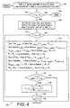
- FIGURE 4 is a flowchart illustrating a preferred method performed by the system shown in Figure 1 for implementing integrated cavity effect correction in accordance with the present invention.
-
- With reference first to FIGURE 1, a preferred processing system 10 for implementing integrated cavity effect correction in scanners will be described. As shown there, a video buffer 12 holds plurality of video values Vi,j representative of the light intensity of a plurality of pixels Pi,j obtained from imaging an original document using a digital scanner device or the like. A first stage processing circuit 14 is adapted to read each of the video values Vi,j in blocks of selected size from each of the pixel locations Pi,j in the video buffer 12 and generate first stage average values Ai,j in accordance with the invention in a manner to be described in detail below. The first stage average values Ai,j are stored in a first stage average buffer 16.
- A second stage processing circuit 18 is adapted to read each of the first stage average values Ai,j in blocks of selected size from the first stage average buffer 16 and generate a second stage average value Bi,j in accordance with the invention. The second stage average values Bi,j are stored in a second stage average buffer 20. Preferably, the block sizes read from the video buffer 12 and from the first stage average buffer 16 are of the same size. However, other differently sized blocks can be used.
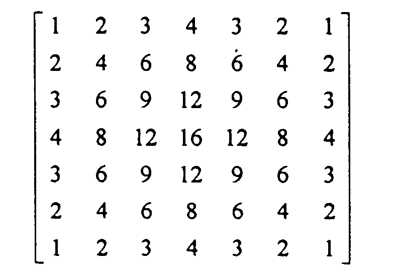
- It is to be appreciated that the present invention exploits the mathematical principle that the double convolution of a 2-D uniform weight filter yields a filter with pyramidal weights. Additional or compounded convolutions of the 2-D uniform weight filter yields filters with weights that are more Gaussian in profile as the multiple convolutions are increased. Double convolution of a 2-D uniform weight filter over a 4 x 4 context yields a filter with a pyramidal shaped weighting profile as follows:
- By way of preliminary example of the preferred embodiment to be described below, let Vij be the video at row i and column j in the video buffer 12 (Figure 1):
V11 V12 V13 V14 V15 V16 V17
V21 V22 V23 V24 V25 V26 V27
V31 V32 V33 V34 V33 V36 V37
V41 V42 V43 V44 V45 V46 V47
V51 V52 V53 V54 V55 V56 V57
V61 V62 V63 V64 V65 V66 V67
V71 V72 V73 V74 V75 V76 V77 - Next, let Sij be the sum of Vij over a region or context of 4 by 4 to the left and above the location i,j as calculated by the first stage processing circuit 14, i.e. Sij is the sum of Vmn for i-4<m<=i and j-4<n<=j.
According to the example, therefore:
The sum values Sij of the video value Vi,j are calculated as above by the first stage processing circuit 14 and put into a matrix form and stored in the first stage average buffer 16 as follows:
S44 S45 S46 S47
S54 S55 S56 S57
S64 S65 S66 S67
S74 S75 S76 S77
Summing the Sij again over a region or context of 4 x 4 to the left and above by the second stage processing circuit 18 yields a set of second sum values Tij for storage in the second stage average buffer 20. As an example:
Accordingly: - The above illustrates that the sum of a sum of a 4 x 4 context yields a pyramidal weighted sum of a 7 x 7 context. In general, a sum of sums of a W by H context yields a pyramidal weighted sum over a context of 2W-1 by 2H-1.
- With continued reference to Figure 1 and with additional reference now to Figure 2, the preferred particular computation of the pyramidal weighted sum in the two-dimensional case with reduced number of multipliers and adders in accordance with the present invention will be described. Preferably, in order to reduce the overall number of bits used, the first stage processing circuit 14 of the subject invention computes the average Ai,j of the video values Vi,j rather than the sum Si,j as described above. Likewise, in the second stage processing circuit 18, the second stage average values Bi,j of the first stage average values Ai,j are computed rather than the strict sum Ti,j as described above. It is to be appreciated, however, that the subject invention embraces both the strict sum calculation to provide the pyramidal weighted sums as described above as well as the average value calculations as described below to compute the pyramidal weighted average for the purposes of reducing the numbers of bits used as well as for reducing the number of multipliers and adders needed.
- Preferably, in accordance with the invention, the video values Vi,j in a window size of W pixels by H scan lines are used by the first stage processing circuit 14 to compute the first stage average values Ai,j for storage in the first stage average buffer 16. Preferably, as shown in Figure 2, a running block 30 of the video values Vi,j is processed by the first stage processing circuit 14 to generate the first stage average values Ai,j. The running block 30 essentially frames pixels of the video buffer 12 to provide a context having a width of W pixels and a height of H scan lines. It is to be appreciated that the video values Vij are retrieved from the video buffer 12 by the first stage processing circuit 14 in a manner so that the running block 30 "progresses" in the pixel direction along the scan lines or, equivalently, to the right as viewed in Figure 2 by a single pixel column at a time. After the running block is "moved" to the rightmost edge of the video values stored in the video buffer 12, the block is shifted downwardly by one scanline and to the extreme left. The running block essentially moves in a raster-like fashion repeatedly to retrieve video values from the next set of scan lines in the video buffer.
- The first stage processing circuit 14 includes a first register 32 for storing a value SumTopj-1 representative of the row sum of the video values at scan line SLi-H+1 from pixel Pj-w to pixel Pj-1. A second register 34 stores the row sum of the video values at scan line SLi from pixel Pj-w to pixel Pj-1. As the image processing performed by the first stage processing circuit 14 proceeds from pixel Pj-1 to pixel Pj, the processing circuit 14 updates the first and second registers 32, 34 according to the following:
- A first-in-first-out (FIFO) buffer 36 is included in the first stage processing circuit 14 to store, at each pixel location, a value Fj which is representative of the sum of the row averages from pixel Pj-W+1 to pixel Pj over scan lines SLi-H+1 to scan line SLi-1. Preferably, in accordance with the present invention, the value Fj is computed in the previous scan line cycle and is thus immediately available from the first FIFO 36. For each pixel location in the video buffer 12, the first stage processing circuit 14 calculates a first stage average value Ai,j according to the following:
- Next, the first stage processing circuit 14 updates the value Fj in the first FIFO 36 for use in the next scan line cycle according to the following:
- With continued reference to Figure 1 and with additional reference now to Figure 3, the second step portion of the processing for computation of the pyramidal weighted average for implementing the integrated cavity effect correction in accordance with the present invention will be described. As discussed above, preferably, in order to reduce the overall number of bits used, the second stage processing circuit 18 of the subject invention computes second stage average values Bij of the first stage average values Aij rather than the strict sum calculation Tij described above. Again, it is to be appreciated that the subject invention embraces both the strict sum calculation to provide the pyramidal weighted average as well as the average value calculations as described herein to compute the pyramidal weighted sums for the purposes of reducing the numbers of bits used as well as for reducing the number of multipliers and adders needed.
- Preferably, in accordance with the invention, the first stage average values Ai,j in a window size of W pixels by H scan lines are used by the second stage processing circuit 18 to compute the second stage average values Bi,j for storage in the second stage average output 20. Preferably, as shown in Figure 3, a running block 40 of the first stage average values Ai,j is processed by the second stage processing circuit 18 to generate the second stage average values Bi,j. The running block 40 essentially frames pixel locations of the first stage average buffer 16 to provide a context having a width of W pixels and a height of H scan lines. It is to be appreciated that the first stage average values Ai,j are retrieved from the buffer 16 by the second stage processing circuit 18 in a manner so that the running block 40 "progresses" in the pixel direction along the scan lines or to the right as viewed in Figure 3 by a single pixel column at a time. After the running block is "moved" to the rightmost edge of the first stage average values Ai,j stored in the first stage average buffer 16, the block is shifted downwardly and to the extreme left. The running block essentially moves in a raster-like fashion repeatedly to retrieve video values from the next set of scan lines in the first stage average buffer 16.
- The second stage processing circuit 18 includes a first register 42 for storing a value Sum2Topj-1 representative of the row sum of first stage average values at scan line SLi from pixel location Pj-1 to pixel location Pj+W-2. A second register 44 stores the row sum of the first stage average values at scan line SLiI+H-1 from pixel location Pj-1 to pixel location Pj+W-2. As the image processing performed by the second stage processing circuit 18 proceeds from pixel location Pj-1 to pixel location Pj, the processing circuit 18 updates the first and second registers 42, 44 according to the following:
- A first-in-first-out (FIFO) buffer 46 is included in the second stage processing circuit 18 to store, at each pixel location, a value F2j which is representative of the sum of the row averages from pixel location Pj to pixel location Pj+W-1 over scan lines SLi to scan line SLi+H-2. Preferably, in accordance with the present invention, the value F2j is computed in the previous scan line cycle and is thus immediately available from the second FIFO 46. For each pixel location in the second stage average buffer 16, the second stage processing circuit 18 calculates a second stage average value Bi,j according to the following:
- Next, the second stage processing circuit 18 updates the value F2j in the second FIFO 46 for use in the next scan line cycle according to the following:
- With reference next to Figure 4, the preferred method 100 for implementing integrated cavity effect correction in accordance with the present invention is shown. With reference now to that figure, a first step 102 initializes the first and second FIFO buffers 32, 46 respectively. In addition, the first step 102 initializes a scan line counter i to an initial value of "1" as well as a set of line buffers V and A to values corresponding to the video values along the extreme edge of the scanned digital image.
- Next, in step 104, the scan line counter value is compared against the sum of a first value Ny representative of the total number of scan lines in the image plus a value H representative of the height in scan lines of the preselected running buffer size. Of course, when the current scan line i exceeds the total number of scan lines in the image plus the height of the running buffer, the method 100 ends at step 106. However, when the current scan line i is yet within the scanned image bounds, an initialization procedure is executed at step 108. More particularly, in step 108, the first and second registers 32, 34 in the first stage processing circuit 14 are initialized as well as the first and second registers 42, 44 in the second stage processing circuit 18. Further in step 108, a new scan line of the video buffer 12 is read into the first stage processing circuit 14 and a parameter j is initialized to a value "1" to designate the first pixel column.
- Next, at step 110, the current pixel column j is compared against a parameter Nx representative of the total number of pixels in an image across the width of the image plus a parameter W representative of the width of the running block 30. When the current pixel column j exceeds the sum of the width of the image Nx plus the width W of the running buffer 30, the parameter i representative of the current scan line is incremented at step 112. On the other hand, when the current pixel column j is less than the sum of the width of the image Nx and the width of the running buffer 30, the processing in block 114 is executed.
- Next, in step 116, the parameter i representative of the current scan line is compared against the height H of the running buffer 30. In addition, the parameter j representative of the current pixel column is compared against a parameter W representative of the width of the running buffer 30. When both the current scan line and the current pixel column are at or exceed the height and width H, W respectively of the running buffer, the integrated cavity effect corrected video ri,j at pixel location P i,j is computed in step 118 in accordance with the following equation:
- In step 120, the parameter j representative of the current pixel column is incremented at step 120. This has the effect of "sliding" each of the running block 30, 40 to the right as viewed in Figures 2 and 3. Thereafter, the method 100 continues at step 110 in a manner described above.
Claims (3)
- A method (100) of determining a weighted average measured reflectance parameter <Rm> for pixels in an image for use in integrated cavity effect correction of the image, the method comprising the steps of:for each pixel of interest Pi,j in said image, computing an approximate spatial dependent average Ai,j, Bi,j of video values in a region of W pixels by H scan lines surrounding the pixel of interest Pi,j by iteratively convolving video values Vi,j of the image in said region with a uniform filter according to:at each pixel of interest Pi,j computing a first average video value Ai,j based on a sum of video values Vi,j within said region of W pixels by H scan lines surrounding said each pixel of interest Pi,j by computing said first average video value Ai,j based on sum of video values Vi,j within a first context from a first video value Vi-H+1,j-W+1 at a first pixel Pi-H+1,j-W+1 to a second pixel Pi-H+1,j in a first scan line SLi-H+1 and from a third pixel Pi,j-W+1 to a fourth pixel Pi,j and a second scan line SLi; and,at each pixel of interest Pi,j, computing a second average video value Bi,j based on a sum of said first average video values Ai,j within said region of said W pixels by H scan lines surrounding said each pixel of interest by computing said second average video value Bi,j based on sum of said first average video values Ai,j within a second context from a first average video value Ai,j at a first pixel Pi,j to a second average video value Ai,j+W-1 at a second pixel Pi,j+W-1 and from a third average video value Ai+H-1, j at a third pixel Pi+H-1,j to a fourth average video value Ai+H-1,j+W-1 at a fourth pixel Pi+H-1,j+W-1; and,for each pixel of interest Pi, j, using a result of the convolving steps as said average reflectance parameter <Rm>.
- A method (100) of determining a weighted average measured reflectance parameter <Rm> for pixels in an image for use in integrated cavity effect correction of the image, the method comprising the steps of:for each pixel of interest Pi,j in said image, computing a spatially dependent sum Si,j, Ti,j of video values in a region of W pixels by H scan lines surrounding the pixel of interest Pi,j by iteratively convolving video values Vi,j of the image in said region with a uniform filter, the convolving including:at each pixel of interest Pi,j computing a first video sum value Si,j based on a sum of video values Vi,j within said region of W pixels by H scan lines surrounding said each pixel of interest Pi,j by computing said first video sum value Si,j based on a sum of video values Vi,j within a first context from a first video value Vi-H+1,j-W+1 at a first pixel Pi-H+1,j-W+1 to a second pixel Pi-H+1j in a first scan line SLi-H+1 and from a third pixel Pi,j-W+1 to a fourth pixel Pi,j and a second scan line SLi; and,at each pixel of interest Pi,j, computing a second video sum value Ti,j based on a sum of said first video sum values Si,j within said region of said W pixels by H scan lines surrounding said each pixel of interest by computing said second video sum value Ti,j based on a sum of said first video sum values Si,j within a second context from a first video sum value Si,j at a first pixel Pi,j to a second video sum value Si,j+W-1 at a second pixel Pi,j+W-1 and from a third video sum value Si+H-1, j at a third pixel Pi+H-1,j to a fourth video sum value Si+H-1,j+W-1 at a fourth pixel Pi+H-1,j+W-1; and,for each pixel of interest Pi, j, using a result of the convolving steps as said average reflectance parameter <Rm>.
- A system (40) for determining a weighted average measured reflectance parameter <Rm> for pixels in an image for use in integrated cavity effect correction of the image, the system comprising:
a set of processing circuits computing, for each pixel of interest Pi,j in said image, an approximate spatial dependent average Ai,j, Bi,j of video values in a region of W pixels by H scan lines surrounding the pixel of interest Pi,j by iteratively convolving video values Vi,j of the image in said region with a uniform filter and, for each pixel of interest Pi, j, using a result of the convolving steps as said average reflectance parameter <Rm>, the set of processing circuits including:a first stage processing circuit (14) for calculating, for said each pixel of interest Pi,j, a sum of video values Vi,j within the region of W pixels by H scan lines as a first result Ai,j, the first stage processing circuit being adapted to compute at each pixel of interest Pi,j, a first average video value Ai,j based on sum of video values Vi,j within said region of W pixels by H scan lines surrounding said each pixel of interest Pi,j; and,a second stage processing circuit (16) for calculating, for said each pixel of interest Pi,j, a sum of said first results Ai,j within said region of W pixels by H scan lines as a second result Bi,j, the second stage processing circuit being adapted to compute at each pixel of interest Pi,j, a second average video value Bi,j based on a sum of said first average video values Ai,j within said region of said W pixels by H scan lines surrounding said each pixel of interest.
Applications Claiming Priority (2)
| Application Number | Priority Date | Filing Date | Title |
|---|---|---|---|
| US448009 | 1999-11-23 | ||
| US09/448,009 US6631215B1 (en) | 1999-11-23 | 1999-11-23 | Method and apparatus for implementing integrated cavity effect correction in scanners |
Publications (1)
| Publication Number | Publication Date |
|---|---|
| EP1104173A2 true EP1104173A2 (en) | 2001-05-30 |
Family
ID=23778654
Family Applications (1)
| Application Number | Title | Priority Date | Filing Date |
|---|---|---|---|
| EP00124925A Withdrawn EP1104173A2 (en) | 1999-11-23 | 2000-11-15 | Method and apparatus for implementing integrated cavity effect correction in scanners |
Country Status (3)
| Country | Link |
|---|---|
| US (1) | US6631215B1 (en) |
| EP (1) | EP1104173A2 (en) |
| JP (1) | JP4698015B2 (en) |
Families Citing this family (2)
| Publication number | Priority date | Publication date | Assignee | Title |
|---|---|---|---|---|
| US8711435B2 (en) * | 2005-11-04 | 2014-04-29 | Xerox Corporation | Method for correcting integrating cavity effect for calibration and/or characterization targets |
| US10616447B1 (en) * | 2019-01-14 | 2020-04-07 | Xerox Corporation | Scanner approximation of an in-line spectrophotometer (ILS) in duplex systems |
Family Cites Families (10)
| Publication number | Priority date | Publication date | Assignee | Title |
|---|---|---|---|---|
| AU565874B2 (en) * | 1983-03-11 | 1987-10-01 | Ei Solutions, Inc. | Adaptive threshold circuit for digital image processing |
| JPS61117974A (en) * | 1984-11-12 | 1986-06-05 | Dainippon Screen Mfg Co Ltd | Method and device for filtering picture signal |
| US5119444A (en) * | 1986-07-22 | 1992-06-02 | Schlumberger Technologies, Inc. | System for expedited computation of laplacian and gaussian filters and correlation of their outputs for image processing |
| US4982294A (en) * | 1987-07-24 | 1991-01-01 | Eastman Kodak Company | Apparatus for enhancing and thresholding scanned microfilm images and methods for use therein |
| JP3107588B2 (en) | 1990-07-02 | 2000-11-13 | 株式会社リコー | Image signal correction method |
| US5604819A (en) * | 1993-03-15 | 1997-02-18 | Schlumberger Technologies Inc. | Determining offset between images of an IC |
| JPH0723226A (en) * | 1993-06-22 | 1995-01-24 | Canon Inc | Image reader |
| US5404232A (en) * | 1993-10-04 | 1995-04-04 | Xerox Corporation | Calibration system for a raster input scanner |
| JP3540914B2 (en) * | 1997-05-19 | 2004-07-07 | 株式会社日立メディコ | X-ray equipment |
| US5790281A (en) * | 1996-10-02 | 1998-08-04 | Xerox Corporation | Method of correcting the measured reflectance of an image acquired by an image acquisition device for the integrating cavity effect |
-
1999
- 1999-11-23 US US09/448,009 patent/US6631215B1/en not_active Expired - Lifetime
-
2000
- 2000-11-15 EP EP00124925A patent/EP1104173A2/en not_active Withdrawn
- 2000-11-21 JP JP2000353666A patent/JP4698015B2/en not_active Expired - Fee Related
Also Published As
| Publication number | Publication date |
|---|---|
| JP2001177726A (en) | 2001-06-29 |
| US6631215B1 (en) | 2003-10-07 |
| JP4698015B2 (en) | 2011-06-08 |
Similar Documents
| Publication | Publication Date | Title |
|---|---|---|
| US5442462A (en) | Apparatus and method for smoothing images | |
| US6285799B1 (en) | Apparatus and method for measuring a two-dimensional point spread function of a digital image acquisition system | |
| US6577762B1 (en) | Background surface thresholding | |
| JP4042563B2 (en) | Image noise reduction | |
| US4774569A (en) | Method for adaptively masking off a video window in an overscanned image | |
| US8594451B2 (en) | Edge mapping incorporating panchromatic pixels | |
| US4833722A (en) | Apparatus and methods for locating edges and document boundaries in video scan lines | |
| US20010008418A1 (en) | Image processing apparatus and method | |
| US8611691B2 (en) | Automated video data fusion method | |
| US20030156201A1 (en) | Systems and methods for processing a digitally captured image | |
| US4982294A (en) | Apparatus for enhancing and thresholding scanned microfilm images and methods for use therein | |
| EP1308889A2 (en) | Method of spatially filtering digital images for noise removal, noise estimation or digital image enhancement | |
| US5623558A (en) | Restoration of images with undefined pixel values | |
| JPH04356869A (en) | Image processor | |
| US7418130B2 (en) | Edge-sensitive denoising and color interpolation of digital images | |
| EP1367537A2 (en) | Calculating noise estimates of a digital image using gradient analysis | |
| EP1227439A2 (en) | Method of calculating noise from a digital image utilizing color cross correlation statistics | |
| US7783125B2 (en) | Multi-resolution processing of digital signals | |
| US4855943A (en) | Method and apparatus for deaveraging a stream of averaged data | |
| US4868670A (en) | Apparatus and method for improving the compressibility of an enhanced image through use of a momentarily varying threshold level | |
| US20070248166A1 (en) | Image stabilization method | |
| US20070132865A1 (en) | Filtered noise reduction in digital images | |
| EP1884893A1 (en) | Sparse integral image description with application to motion analysis | |
| Taylor et al. | Enhancement of document images from cameras | |
| US6631215B1 (en) | Method and apparatus for implementing integrated cavity effect correction in scanners |
Legal Events
| Date | Code | Title | Description |
|---|---|---|---|
| PUAI | Public reference made under article 153(3) epc to a published international application that has entered the european phase |
Free format text: ORIGINAL CODE: 0009012 |
|
| AK | Designated contracting states |
Kind code of ref document: A2 Designated state(s): AT BE CH CY DE DK ES FI FR GB GR IE IT LI LU MC NL PT SE TR |
|
| AX | Request for extension of the european patent |
Free format text: AL;LT;LV;MK;RO;SI |
|
| STAA | Information on the status of an ep patent application or granted ep patent |
Free format text: STATUS: THE APPLICATION IS DEEMED TO BE WITHDRAWN |
|
| 18D | Application deemed to be withdrawn |
Effective date: 20150602 |