EP1104139A2 - Setting of decision thresholds and sampling phase - Google Patents
Setting of decision thresholds and sampling phase Download PDFInfo
- Publication number
- EP1104139A2 EP1104139A2 EP00310332A EP00310332A EP1104139A2 EP 1104139 A2 EP1104139 A2 EP 1104139A2 EP 00310332 A EP00310332 A EP 00310332A EP 00310332 A EP00310332 A EP 00310332A EP 1104139 A2 EP1104139 A2 EP 1104139A2
- Authority
- EP
- European Patent Office
- Prior art keywords
- signal
- data signal
- incoming data
- sampling
- pseudo
- Prior art date
- Legal status (The legal status is an assumption and is not a legal conclusion. Google has not performed a legal analysis and makes no representation as to the accuracy of the status listed.)
- Withdrawn
Links
- 238000005070 sampling Methods 0.000 title claims abstract description 210
- 230000001172 regenerating effect Effects 0.000 claims abstract description 78
- 238000012544 monitoring process Methods 0.000 claims abstract description 70
- 238000000034 method Methods 0.000 claims abstract description 39
- 230000008929 regeneration Effects 0.000 claims abstract description 36
- 238000011069 regeneration method Methods 0.000 claims abstract description 36
- 230000004399 eye closure Effects 0.000 claims description 48
- 238000010586 diagram Methods 0.000 claims description 20
- 238000013507 mapping Methods 0.000 claims description 15
- 238000004891 communication Methods 0.000 claims description 7
- 230000003111 delayed effect Effects 0.000 claims 13
- 238000011084 recovery Methods 0.000 claims 10
- 239000013074 reference sample Substances 0.000 claims 5
- 238000005457 optimization Methods 0.000 abstract description 22
- 230000008569 process Effects 0.000 abstract description 6
- 230000001939 inductive effect Effects 0.000 abstract description 4
- 230000005540 biological transmission Effects 0.000 description 22
- 230000033590 base-excision repair Effects 0.000 description 16
- 238000005259 measurement Methods 0.000 description 14
- 230000008859 change Effects 0.000 description 12
- 230000015556 catabolic process Effects 0.000 description 5
- 238000012937 correction Methods 0.000 description 5
- 238000006731 degradation reaction Methods 0.000 description 5
- 230000014509 gene expression Effects 0.000 description 5
- 101100478363 Saccharomyces cerevisiae (strain ATCC 204508 / S288c) BER1 gene Proteins 0.000 description 4
- 230000007423 decrease Effects 0.000 description 4
- 238000001514 detection method Methods 0.000 description 4
- 230000000630 rising effect Effects 0.000 description 3
- 230000003044 adaptive effect Effects 0.000 description 2
- 230000008901 benefit Effects 0.000 description 2
- 238000004590 computer program Methods 0.000 description 2
- 230000001419 dependent effect Effects 0.000 description 2
- 230000003287 optical effect Effects 0.000 description 2
- 230000003321 amplification Effects 0.000 description 1
- 238000013459 approach Methods 0.000 description 1
- 239000003990 capacitor Substances 0.000 description 1
- 230000000295 complement effect Effects 0.000 description 1
- 239000004020 conductor Substances 0.000 description 1
- 238000005516 engineering process Methods 0.000 description 1
- 230000007246 mechanism Effects 0.000 description 1
- 238000012986 modification Methods 0.000 description 1
- 230000004048 modification Effects 0.000 description 1
- 238000003199 nucleic acid amplification method Methods 0.000 description 1
- 238000013139 quantization Methods 0.000 description 1
- 230000004043 responsiveness Effects 0.000 description 1
- 238000012552 review Methods 0.000 description 1
- 238000010079 rubber tapping Methods 0.000 description 1
- 239000004065 semiconductor Substances 0.000 description 1
- 230000035945 sensitivity Effects 0.000 description 1
Images


Classifications
-
- H—ELECTRICITY
- H04—ELECTRIC COMMUNICATION TECHNIQUE
- H04L—TRANSMISSION OF DIGITAL INFORMATION, e.g. TELEGRAPHIC COMMUNICATION
- H04L25/00—Baseband systems
- H04L25/02—Details ; arrangements for supplying electrical power along data transmission lines
- H04L25/06—DC level restoring means; Bias distortion correction ; Decision circuits providing symbol by symbol detection
- H04L25/061—DC level restoring means; Bias distortion correction ; Decision circuits providing symbol by symbol detection providing hard decisions only; arrangements for tracking or suppressing unwanted low frequency components, e.g. removal of DC offset
- H04L25/062—Setting decision thresholds using feedforward techniques only
Definitions
- the present invention is directed to data regeneration and more particularly to a method and apparatus for regenerating data signals in a more optimal fashion than hitherto.
- interconnecting links such as twisted pair metallic conductors, coaxial cables, fibre-optic cables, radio frequency wireless channels or over the air infra-red channels.
- the maximum distance over which information can be reliably transmitted in a network is mainly dictated by the type of interconnecting links used but is also dependent upon other factors such as the transmit power launched, transmission losses and the sensitivity of optical receivers used in the network terminals.
- transit terminals such as repeaters and amplifiers are commonly used along the transmission path for signal amplification and regeneration.
- BER bit error rate
- An eye closure diagram is useful for evaluating the transmission performance of a particular transmission link and can be used in a receiver for regenerating data.
- the ability of a receiver to regenerate data received from a particular transmission link is dependent upon a threshold level or slicing threshold and a sampling phase. By monitoring the eye closure of the incoming signal, the optimum slicing threshold and sampling phase for the receiver can be determined more easily.
- U.S. Patent No. 4,823,360 entitled “Binary data regenerator with adaptive threshold level” which issued on April 18, 1989 to Tremblay et al. discloses a data regenerator which dynamically monitors the eye closure of an incoming data signal for regeneration.
- the data regenerator disclosed in the 360 patent uses two slicing thresholds within the data eye (hereinafter referred to as “reference slicing thresholds”) for producing "pseudo-errors" at a preset BER on binary ones and zeros of the data signal.
- the pseudo-errors do not appear on the in-service data path and as a result, do not affect the data regeneration.
- the thresholds are dynamically adjusted so that the number of pseudo-errors generated on binary ones and zeros is maintained to correspond to the preset BER.
- the data regenerator operates to set a third slicing threshold level (hereinafter the "data slicing threshold") optimally within the data eye in relation to the reference slicing thresholds and move the placement of this threshold as a function of time within the eye to produce an optimum slicing level at an optimum sampling phase.
- data slicing threshold a third slicing threshold level
- the technique disclosed in the 360 patent provides some measure of the transmission link performance as a function of slicing level and sampling phase and is particularly useful to regenerate incoming data with an optimally placed slicing threshold.
- a disadvantage of this approach is that the optimization of the data slicing threshold and sampling phase is carried out on the in-service data path while the incoming data is being regenerated.
- the optimization of the data slicing threshold and sampling phase is carried out on the in-service data path while the incoming data is being regenerated.
- error correction codes such as a forward error correction (FEC) codes.
- FEC forward error correction
- the error correction codes are typically embedded in the data signal at the transmitting site before transmission.
- the errors present in the regenerated data signal can be detected and corrected by comparing the codes received with the known codes transmitted.
- the operation of the data regenerator disclosed in the 391 patent is divided into an error mapping mode, an optimization mode and a data regeneration mode. More specifically, the data regenerator functions in the error mapping mode to monitor the eye closure by preparing a BER map of the incoming data signal.
- the data generator can also operate in the optimization mode to determine based on the BER map prepared, an optimum data slicing threshold and sampling phase placement within the data eye. With the slicing threshold and sampling phase optimized, the data regenerator can operate in a data regeneration mode to regenerate the incoming data signal.
- the data regenerator disclosed by the 391 patent operates in separate modes for BER mapping, optimization of the slicing threshold and sampling phase, and data regeneration, actual errors are nevertheless generated on the in-service data path during the BER mapping and optimization process.
- the data regenerator disclosed therein would be appropriate for proprietary data signals with proprietary data rates which do not require frequent BER mapping and optimization updates as the eye closure in such cases remains essentially the same.
- the present invention addresses these issues and to this end provides a methodology and apparatus to mitigate the present limitations in this art.
- An embodiment of the invention provides a method and apparatus for efficiently regenerating an incoming data signal at a sampling point which is continually optimized independently of the regeneration process. While the incoming data signal is being regenerated in a regeneration unit, this embodiment of the invention uses a monitoring unit for concurrently optimizing the slicing threshold and sampling phase used in the regeneration unit without disturbing the on-going data regeneration.
- the invention preferably uses a master-slave arrangement to regenerate the incoming data signal whereby the regenerating unit is updated with a new slicing threshold and sampling phase only after the new slicing threshold and sampling phase are fully optimized by the monitoring unit.
- the data regeneration can proceed unaffected by the optimization of the slicing threshold and sampling phase which, as a result can be continuously optimized without inducing any errors into the regenerated data.
- the invention is embodied in a data regenerator which has a regenerating unit for regenerating the incoming signal, a monitoring unit for optimizing the slicing threshold and the sampling phase, and a control unit for controlling the data regeneration and the optimization in a master-slave arrangement.
- the monitoring unit monitors the incoming signal eye closure for evaluating transmission performance and determining an optimum slicing threshold and sampling phase within the eye closure.
- the monitoring unit While the incoming data signal is being regenerated, the monitoring unit performs eye measurements on the incoming data signal which are then forwarded to the control unit where they are processed to obtain bit error rate (BER) contours and establish a BER map of the eye closure. Based on this BER map, the control unit can determine whether the existing sampling point used in the regenerating unit is optimally placed within the eye closure or whether it needs to be updated. If an update is necessary to maintain the data regeneration optimum, the control unit uses the BER map to determine a new slicing threshold and sampling phase. Once determined, the new slicing threshold and sampling phase are then forwarded to the regenerating unit which as a result operates to regenerate the incoming data signal at the optimized sampling point until further optimization is carried out.
- BER bit error rate
- the data regeneration is not disturbed by the optimization of the slicing threshold and sampling phase. Because the optimization process does not affect data regeneration, the described embodiments of the invention do not introduce errors into the regenerated data. As such, the described embodiments of the invention are particularly well suited for protocol independent data regenerators where the eye closure continuously changes requiring frequent BER map and optimization updates.
- Another advantage of the described embodiments of the present invention is that the signal eye closure can be monitored independently of any proprietary information or protocols.
- the invention can also advantageously be used for adjusting other parameters such as detector bias and equalizer tuning for optimum performance.
- Preferred embodiments of the invention provide a method and apparatus for efficiently regenerating an incoming data signal at a sampling point which is continually optimized independently of the regeneration process. While the incoming data signal is being regenerated in a regeneration unit, the preferred embodiments use a monitoring unit for concurrently optimizing the slicing threshold and sampling phase used in the regeneration unit without disturbing the on-going data regeneration.
- the invention preferably uses a master-slave arrangement to regenerate the incoming data signal whereby the regenerating unit is updated with a new slicing threshold and sampling phase only after the new slicing threshold and sampling phase are fully optimized by the monitoring unit.
- the data regeneration can proceed unaffected by the optimization of the slicing threshold and sampling phase which, as a result can be continuously optimized without inducing any errors into the regenerated data.
- the invention preferably uses an eye closure diagram for evaluating the performance of the transmission link and determining an optimum slicing threshold and sampling phase within the eye closure.
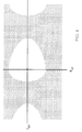
- Figure 1 is a typical eye closure diagram of an incoming data signal received over a transmission link illustrating a slicing threshold V opt and a sampling phase ⁇ opt optimally placed within the eye closure for optimum regeneration of the data received.
- the vertical coordinate of the eye closure diagram represents the voltage (power) amplitude of the received signal and the horizontal coordinate represents time.
- the eye closure of the incoming data signal must be continuously monitored to update the slicing threshold and sampling phase whenever necessary so that the incoming data signal can be optimally regenerated.
- Figure 2 shows a data regenerator 10 according to a preferred embodiment of the invention that uses different circuits for eye monitoring and data regeneration of an incoming signal S in (t).
- the control unit 16 Based on these references REFH, REFL, REFD, the control unit 16 produces a reference data REFD' and a reference phase REFP' to the regenerating unit 14.
- the regenerating unit 14 is coupled to receive the incoming data signal S in (t) and uses the reference data REFD' as a slicing threshold and the reference phase REFP' as a sampling phase to optimally produce a regenerated output data signal S out (t).
- the invention preferably uses a master-slave arrangement to regenerate the incoming data signal S in (t) whereby the regenerating unit 14 is updated with a new slicing threshold and sampling phase only after the new slicing threshold and sampling phase are fully optimized by the monitoring unit 14.
- the data regeneration can proceed unaffected by the optimization of the slicing threshold and sampling phase which, as a result can be continuously optimized without inducing any errors into the regenerated data.
- the eye measurements taken in the monitoring unit 12 are forwarded to the control unit 16 via the reference levels REFH, REFL and REFD.
- the eye measurements received are processed to obtain bit error rate (BER) contours and establish a BER map of the eye closure. Based on this BER map, the control unit 16 can determine whether the existing sampling point used in the regenerating unit 14 is optimally placed within the eye closure or whether it needs to be updated. An update would be required where, for example, the eye closure changes shape due to variations of the data signal bit rate or variations of the transmission conditions. By continuously taking measurements in the monitoring unit 12, any change in the data eye closure will be detected.
- the control unit 16 uses the eye measurements obtained from the monitoring unit 12 to determine a new slicing threshold and sampling phase which accounts for the eye closure variation detected.
- the control unit 16 updates the REFD' and REFP' references to reflect the change.
- the regenerating unit 14 operates to regenerate the incoming data signal S in (t) at the optimized sampling point denoted by REFD' and REFP' until further optimization is carried out.
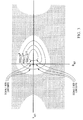
- FIG. 3 an eye closure diagram for the incoming data signal S in (t) is shown with three BER contours denoted by BER1, BER2 and BER3.
- Each BER contour BER1, BER2, BER3 is formed of a signal one BER contour and a signal zero BER contour and are each associated to a particular BER.
- contour BER1 (signal one and zero BER contours) corresponds to a BER of 10 -12
- contour BER2 (signal one and zero BER contours) corresponds to a higher BER of 10 -9
- contour BER3 (signal one and zero BER contours) to a BER of 10 -6 . From these contours BER1, BER2, BER3, the control unit 16 can determine whether the existing sampling point (defined by REFD' and REFP') used in the regenerating unit 14 is optimally placed within the eye closure or whether optimization is required.
- Each BER contour is obtained by varying the reference phase REFP in the control unit 16 and taking BER measurements of the incoming signal S in (t) in the monitoring unit 12 for each reference phase REFP.
- the monitoring unit 12 uses the REFH and REFL references as slicing thresholds to generate pseudo-errors on binary ones and zeros of the incoming signal S in (t).
- REFH threshold pseudo-errors are generated on binary ones of the incoming data signal S in (t).
- REFL threshold pseudo-errors are generated on binary zeros of the incoming signal S in (t).
- the REFH and REFL references are feedback adjusted based on the number of pseudo-errors generated until the predetermined BER is obtained.
- the adjusted REFH and REFL references are then recorded in the control unit 16 to denote the predetermined BER within the eye closure at the particular reference phase REFP.
- a BER contour can be obtained. The process is repeated for assessing additional BER contours and obtain a BER map of the entire data eye closure.
- the monitoring unit 12 described above for monitoring the incoming data eye closure is implemented based on the data regenerator architecture disclosed in U.S. Patent No. 4,823,360 entitled “Binary data regenerator with adaptive threshold level” which issued on April 18, 1989 to Tremblay et al. (hereinafter referred to the "360 patent").
- the following section will now describe in detail the architecture and operation of the monitoring unit 12. For any further information, reference may be made to the 360 patent.
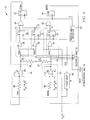
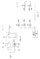
- Figure 4 shows as an example, a more detailed diagram of the monitoring unit 12 based on the data regenerator architecture disclosed in the 360 patent.
- three pseudo channels generally indicated by 20, 22 and 24 are used for assessing BER contours of the incoming data eye closure.
- a first pseudo channel 20 (hereinafter also referred to as the "upper pseudo channel”) is used for generating pseudo-errors on binary ones of the incoming data signal S in (t) at various BERs so that different signal one BER contours can be assessed.
- a second pseudo channel 24 (hereinafter also referred to as the "lower pseudo channel”) is used for generating pseudo-errors on binary zeros on the incoming data signal S in (t) at various BERs so that multiple signal zero BER contours can be obtained.
- a third channel generally indicated by 22 (hereinafter also referred to as the "reference channel") is used to provide a center reference for the BER measurements in the other upper and lower pseudo channels 20, 24 (further details below).
- the upper and lower pseudo channels 20, 24 each consists of a differential amplifier 26, 34 connected in series with a D-type flip-flop 28, 36.
- the differential amplifiers 26, 34 are coupled to receive the incoming data signal S in (t) in a non-inverting (+) input.
- the differential amplifier 26 In an inverting (-) input, the differential amplifier 26 is coupled to receive the REFH reference and produces its output to a data input D of the flip-flop 28.
- the differential amplifier 34 is coupled in an inverting input to receive the REFL reference for producing its output to a data input D of the flip-flop 36.
- the flip-flops 28, 36 are each clocked with a sampling clock signal CLK derived from the incoming signal S in (t) through a phase delay 62. More specifically, the sampling clock signal CLK is obtained in the phase delay 62 by recovering a clock signal from the incoming signal S in (t) and adjusting the phase of the recovered clock with the REFP reference. The phase delay 62 displaces the recovered clock pulses according to the REFP reference phase produced by the control unit 16.
- the sampling clock CLK is fed into the flip-flops 28, 36 which as a result, produce in a Q output a respective pseudo data channel signal 29, 31.
- the pseudo output data signals 29, 31 produced by the upper and lower pseudo channels 20, 24 can be viewed as pseudo regenerated data signals respectively produced in relation to the reference thresholds REFH and REFL.
- the reference channel 22 is comprised of a differential amplifier 30 and a D-type flip-flop 32.
- the differential amplifier 30 is coupled to receive the incoming data signal S in (t) in a non-inverting (+) input and the REFD reference in an inverting input (-) for producing an output to the associated flip-flop 32 via a data input D.
- the flip-flop 32 is also coupled to receive in a clock input C the sampling clock signal CLK derived from the incoming signal S in (t) through the phase delay 62 for producing a reference data signal 33 in a Q output.
- the reference data signal 33 produced by the reference channel 22 can be viewed as a pseudo regenerated data signal produced in relation to the reference threshold REFD.
- Each pseudo output data signals 29, 31 is coupled to a control loop formed of an exclusive-OR gate 38, 40, a pulse stretching unit 42, 44 and an inverting integrator generally indicated by 46, 48 for producing the REFH and REFL references respectively. More specifically, the pseudo output data signals 29, 31 are respectively gated to the exclusive-OR gates 38, 40 with the reference data signal 33 produced by the reference channel 22. As a result, the gates 28, 40 produce a logic one output whenever regenerated data at the output of the respective pseudo channels 20, 24 is in error relative to the regenerated data at the output of the reference channel 22. By operation of these gates 38, 40, pseudo-errors produced in the pseudo channels 20, 24 on binary ones and zeros of the incoming data signal S in (t) can be detected.
- the outputs of the gates 38, 40 are respectively coupled to the pulse stretching units 42, 44 to stretch the pseudo-errors detected.
- Various components can be used to implement this pulse stretching function such as, for example, flip-flops or digital counters.
- Figure 4 shows as an example the pulse stretching units 42, 44 each implemented with a respective set-reset flip-flop.
- the pulse stretching units 42, 44 are also connected to receive in a respective R input, the clock signal PCLK provided by the control unit 16 through a positive edge detector 64.
- the control unit 16 produces the PCLK signal at a variable frequency which is typically much lower than the frequency of the sampling clock signal CLK.
- the PCLK signal acts as a reset clock.
- the pulse stretching unit 42 produces in a Q output an output signal ERRH formed of stretched binary one pseudo errors which is reset at the PCLK rate.
- the pulse stretching unit 44 produces in a QN output an output signal NERRL formed of stretched binary zero pseudo errors which is also reset at the PCLK rate.
- the output signals ERRH and NERRL are each defined with a low logic level V ol and a high logic level V oh . These output signals ERRDH and ERRDL are respectively fed into the inverting integrators 46, 48.
- the inverting integrators 46, 48 are each formed of a series resistor 50, 56, a differential amplifier 54, 60 and a feedback capacitor 52, 58.
- the inverting integrators 46, 48 are referenced to a predetermined direct current (DC) offset (V ol + V oh )/2 via a non-inverting input (further details below) and respectively operate to produce the REFH and REFL references.
- the REFH and REFL references are supplied to a voltage divider formed of two resistors 66, 67 to produce at its tapping point the REFD reference which is used in the reference channel 22.
- the monitoring unit 12 takes BER measurements of the incoming signal S in (t) for different reference phases REFP. As noted above, in order to measure a particular BER for a particular reference phase REFP, the monitoring unit 12 uses the REFH and REFL references as slicing thresholds in the upper and lower pseudo-channels 20, 24 to generate pseudo-errors on binary ones and zeros of the incoming signal S in (t).
- the pseudo-errors generated in the upper and lower pseudo-channels 20, 24 are produced in reference to the reference data signal 33. More specifically, a pseudo-error on binary ones of the incoming signal S in (t) will be produced whenever regenerated data at the output of the upper pseudo channel 20 is in error relative to the regenerated data at the output of the reference channel 22. Similarly, a pseudo-error on binary zeros of the incoming signal S in (t) will be produced whenever regenerated data at the output of the lower pseudo-channel 24 is in error relative to the regenerated data at the output of the reference channel 22.
- the reference channel 22 uses the REFD reference as a slicing threshold to provide a center reference for the generation of pseudo-errors in the upper and lower pseudo channels 20, 24.
- the REFD reference is set by the voltage divider 66 to an optimal value between the REFH and REFL references with a predetermined ratio thereto.
- the manner in which the REFD reference is derived from the REFH and REFL references is not unique.
- K is a positive fraction chosen so that REFD is optimally placed between REFH and REFL.
- the value of K would be typically less than 0.5 and could be for example in the range from 0.3 to 0.5.
- the REFH and REFL references are feedback adjusted until the upper and lower pseudo-channels generate pseudo-errors at a predetermined BER.
- the adjusted REFH and REFL references are then recorded in the control unit 16 to denote the predetermined BER within the eye closure.
- the pulse stretching unit 42 produces the ERRH signal at a predetermined mean duty cycle so that the REFH reference can be maintained at the appropriate slicing level.
- the integrator 46 continually forces the ERRH mean duty cycle to its predetermined value. If the ERRH mean duty cycle changes, the integrator 46 immediately counteracts by appropriately adjusting the REFH reference level to force a corresponding change in the number of pseudo-errors generated such that the ERRH mean duty cycle is maintained constant.
- the number of pseudo-errors produced in the upper pseudo-channel 20 is closely related to the duty cycle of the ERRH signal. For example, if the number of pseudo-errors generated increases, the ERRH duty cycle increases. Conversely, if the number of pseudo-errors generated decreases, the ERRH duty cycle decreases.
- the ERRH duty cycle will increase causing the integrator 46 to immediately decrease the REFH reference. If the REFH reference is set too low, not enough pseudo-errors are generated and as a result, the ERRH duty cycle decreases causing the integrator 46 to increase the REFH reference. This negative feedback maintains the REFH reference to a level that allows the upper pseudo-channel 20 to produce pseudo-errors at the predetermined BER.
- the integrator's responsiveness to changes in the ERRH mean duty cycle is based on resulting changes induced in the ERRH direct current (DC) level.
- DC direct current
- the integrator 46 forces the ERRH DC level to be equal to the integrator DC offset. Any change in the ERRH duty cycle causes a corresponding change in the ERRH DC level which in turn causes the integrator 46 to adjust the REFH reference until the ERRH DC level is equal again to the integrator DC offset.
- the REFH reference is always adjusted to a level that maintains the ERRH DC level equal to the integrator DC offset.
- the integrator DC offset is set to (V ol + V oh )/2 which forces the ERRH DC level to be (V ol + V oh )/2.
- the integrator 46 maintains the ERRH mean duty cycle to a constant value of 50 percent. Any change in the ERRH duty cycle causes a corresponding change in the ERRH DC level which in turn causes the integrator 46 to adjust the REFH reference until the ERRH DC level is equal again to the DC offset of (V ol + V oh )/2.
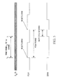
- FIG. 5 a timing diagram of the incoming signal S in (t), the PCLK signal and the resulting ERRH signal produced by the pulse stretching unit 42.
- the ERRH signal is set at the occurrence of a first pseudo-error detected by the gate 38 and reset at the start of the next PCLK rising edge.
- Figure 5 shows the ERRH signal set at a random time T after the occurrence of a preceding PCLK rising edge defined to occur at time t 0 .
- the ERRH duty cycle extends from T where a first pseudo-error is detected to the time at which the next PCLK rising edge occurs to reset ERRH.
- the ERRH duty cycle is a function of both the time T and the PCLK period T.
- the ERRH duty cycle will be large. Conversely, if the time T is long, the ERRH duty cycle will be shorter. Because of this dependence, the number of pseudo-errors generated in the upper pseudo-channel 20 has a direct impact on the mean duty cycle of the ERRH signal. If the upper pseudo-channel 20 is producing pseudo-errors at a predetermined BER (determined by the PCLK period T), any deviation in the ERRH mean duty cycle will cause the integrator 46 to immediately adjust the REFH reference so that the predetermined BER is maintained.
- the control unit 16 introduces a change in the ERRH duty cycle by varying the PCLK period T.
- the duty cycle change triggers the integrator 46 to adjust the REFH reference to a level that causes the ERRH mean duty cycle to be forced back to its predetermined value.
- the REFH reference would be adjusted such that the ERRH mean duty cycle would be forced back to 50%.
- the integrator 46 would adjust the REFH reference to a level that causes the ERRH DC level to be forced back to (V ol + V oh )/2.
- the upper pseudo-channel 20 can produce pseudo-errors at different predetermined BERs.
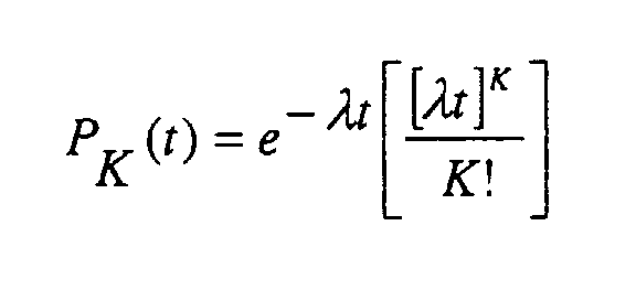
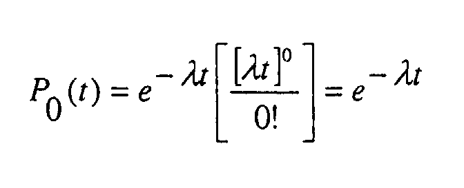
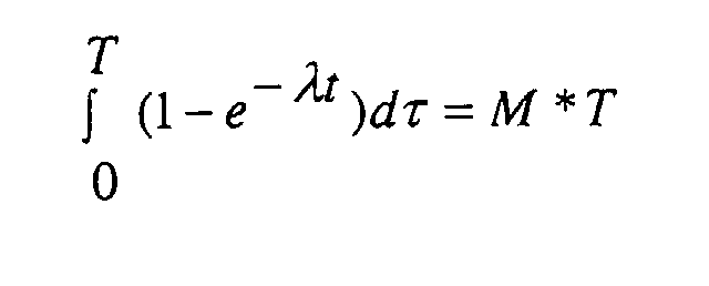
- the probability P ( K ⁇ 1) (t) integrated over a time period T is equal to the ERRH mean pulse width PW: where ⁇ is the number of pseudo-errors per second on binary ones of the incoming data signal S in (t).
- the following table contains different BERs calculated for a 2.5Giga bit per second (Gb/s) data signal for three different PCLK periods 1.28mS, 128 ⁇ S and 12.8 ⁇ S.
- the PCLK periods are shown in a first column and the corresponding BERs are shown in a second column.
- PCLK PERIOD T CALCULATED BER 1.28mS 1.0 * 10 -6 128 ⁇ S 1.0 * 10 -5 12.8 ⁇ S 1.0 * 10 -4
- the resulting change in the ERRH duty cycle causes the integrator 46 to adjust the REFH reference until the ERRH mean duty cycle M is forced back to a predetermined value (e.g. 50%).
- a predetermined value e.g. 50%
- the upper pseudo-channel 20 generates pseudo-errors at the predetermined BER such that the ERRH mean duty cycle M is maintained constant.
- the adjusted REFH reference is then recorded in the control unit 16 to denote the predetermined BER.
- the monitoring unit 12 described above in relation to Figures 2, 3, 4 and 5 is only illustrative of a particular implementation example where the REFH and REFL references are internally adjusted to produce pseudo-errors on binary ones and zeros of the incoming data signal S in (t) at predetermined BERs. It will be apparent that alternatives are possible.
- the integrators 46, 48 could be external to the monitoring unit 12. In fact, the adjustment mechanism could be implemented without any integrators 46, 48 and directly into the control unit 16.
- Figure 6 shows another monitoring unit 70 where the REFH and REFL references are adjusted externally by the control unit 16.
- the ERRH and NERRL signals are forwarded externally to the control unit 16 to produce the REFH and REFL references via a respective D/A converter 72, 74.
- the architecture and mode of operation of the monitoring unit 70 is identical to that of the monitoring unit 12 described above in relation to Figures 2, 3, 4 and 5.
- the REFH and REFL references can be more accurately controlled by the control unit 16 so that the upper and lower pseudo-channels 20, 24 can produce pseudo-errors at predetermined BERs.
- each signal one and signal zero BER contour is obtained by varying the reference phase REFP in the control unit 16, predetermining different BERs for each reference phase REFP by varying the PCLK period T, and measuring the REFH and REFL reference levels adjusted for each predetermined BER.
- the control unit 16 can obtain signal one and signal zero BER contours referenced to the REFD reference and establish a BER map of the entire eye closure. Based on this BER map, the control unit 16 can determine whether the existing sampling point (REFD' and REFP') used in the regenerating unit 14 is optimally placed within the eye closure or whether it needs to be updated.
- FIG. 7 shows the control unit 16 in further detail.
- the REFP reference phase used by the monitoring unit 12 is generated by a digital controller 90 to the monitoring unit 12 through a digital-to-analog (D/A) converter 86.
- the REFD reference produced by the monitoring unit 12 based on the REFH and REFL references is coupled to the digital controller 90 through an analog-to-digital (A/D) converter 80.
- the REFH and REFL references produced by the monitoring unit 12 are also coupled to the digital controller 90 but through a differential A/D converter 82 for subtracting REFL from REFH first and produce a single digital signal REFH - REFL to the digital controller 90.
- the REFH - REFL and REFD signals are processed to produce the reference data REFD' and reference phase REFP' to the regenerating unit 14 for optimally regenerating the incoming data signal S in (t).
- the digital controller 90 could set REFP' to a sampling phase REFP where the difference between the measured REFH and REFL reference levels is maximized.
- an optimum slicing threshold REFD' in the digital controller 90 based on the REFH REFL and REFD references.
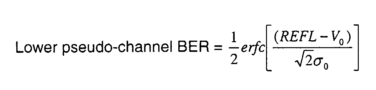
- the various predetermined BERs and corresponding REFH and REFL reference values obtained could be used to determine a mean level V 1 , V 0 and a standard deviation ⁇ 1 , ⁇ 0 for binary ones and binary zeros of the incoming signal S in (t).
- V 1 , V 0 ⁇ 1 , ⁇ 0 could be calculated by using well-known complementary error function expressions for the upper and lower pseudo-channel BERs given as: and
- the digital controller 90 could determine REFD' as follows:
- V 1 , V 0 , ⁇ 1 , and ⁇ 0 are calculated, other transmission parameters could be determined.
- the control unit 16 updates the existing sampling point.
- the regenerating unit 14 begins to regenerate the incoming data signal S in (t) at the optimized sampling point (REFD' and REFP') until further optimization is carried out.
- a data channel generally indicated by 106 and a phase delay 104 are used to regenerate the incoming data signal S in (t) and produce the regenerated data signal S out (t).
- the data channel 106 of the regenerating unit 14 consists of a differential amplifier 100 connected in series with a D-type flip-flop 102. More specifically, the differential amplifier 100 is coupled to receive the incoming data signal S in (t) in a non-inverting input and the REFD' reference in an inverted input. The output of the differential amplifier 100 is coupled to a data input D of the D-type flip-flop 102.
- the flip-flop 102 is also coupled to receive in a clock input C a sampling clock signal CLK' which is recovered from the incoming signal S in (t) through the phase delay 104.
- the phase delay 104 re-times the recovered sampling clock signal CLK' by introducing a delay which corresponds to REFP' reference supplied by the control unit 16.
- the regenerating unit 14 optimally regenerates the incoming data signal S in (t) by using the slicing threshold REFD' and the sampling phase REFP'. With the REFD' and REFP' references produced by the control unit 16 and not directly by the monitoring unit 12, the regenerating unit 14 can regenerate the incoming data without any disruption from the monitoring process. While the incoming data signal S in (t) is regenerated, the monitoring unit 12 is free to perform BER measurements on the incoming data signal S in (t) as described above so that the control unit 16 can fully monitor the data eye closure without interrupting regeneration and introducing errors in the regenerated data.
- the monitoring unit has been described above as being used to optimize both a data slicing threshold REFD' and sampling phase REFP' which together define an optimal sampling point for data regeneration.
- the invention could alternatively be used to optimize only the data slicing threshold REFD' without optimizing the data sampling phase REFP'.
- the reference sampling phase REFP supplied to the monitoring unit would be maintained fixed while the PCLK clock signal would be varied to predetermine different BERs in the monitoring unit and determine an optimal data slicing threshold REFD'.
- the invention could also be used to optimize the optimal data sampling phase REFP' for a fixed (or predetermined) data slicing threshold REFD'.
- the PCLK clock signal would be maintained constant to implement the fixed (or predetermined) BER in the monitoring unit and the reference sampling phase REFP would be varied to determine an optimal data sampling phase REFP'.
- Alternative embodiments of the invention can be implemented as a computer program product for use with a computer system, the computer program product being, for example, a series of computer instructions stored on a tangible data recording medium, such as a diskette, CD-ROM, ROM, or fixed disk, or embodied in a computer data signal, the signal being transmitted over a tangible medium or a wireless medium, for example microwave or infrared.
- the series of computer instructions can constitute all or part of the functionality described above, and can also be stored in any memory device, volatile or nonvolatile, such as semiconductor, magnetic, optical or other memory device.
Landscapes
- Engineering & Computer Science (AREA)
- Power Engineering (AREA)
- Computer Networks & Wireless Communication (AREA)
- Signal Processing (AREA)
- Dc Digital Transmission (AREA)
- Optical Communication System (AREA)
Abstract
Description

| PCLK PERIOD T | CALCULATED BER |
| 1.28mS | 1.0 * 10-6 |
| 128µS | 1.0 * 10-5 |
| 12.8µS | 1.0 * 10-4 |


Claims (46)
- A method of regenerating an incoming data signal in a receiver at an optimized sampling point to produce an optimally regenerated data signal, the method comprising continuously:regenerating in a regenerating unit the incoming data signal at a sampling point to produce a regenerated data signal;regenerating in a monitoring unit the incoming data signal at different reference sampling points to produce a first pseudo regenerated data signal with pseudo-errors at different bit error rates (BERs) for establishing a BER map of the incoming data signal;determining based on the BER map established whether the sampling point is optimal;if the sampling point is not optimal, determining an optimal sampling point and applying the optimal sampling point determined in the regenerating unit to regenerate the incoming data signal optimally for producing the optimally regenerated data signal.
- The method of claim 1 wherein the sampling point consists of a slicing threshold and a sampling phase and the optimal sampling point consists of an optimal slicing threshold and an optimal sampling phase.
- The method of claim 1 wherein the sampling point consists of a slicing threshold and the optimal sampling point consists of an optimal slicing threshold.
- The method of claim 2 wherein regenerating in a monitoring unit the incoming data signal at different reference sampling points to produce a first pseudo regenerated data signal with pseudo-errors at different BERs for establishing a BER map of the incoming data signal comprises:a) recovering a clock signal from the incoming data signal;b) predetermining a BER;c) selecting a reference sampling phase;d) phase delaying the recovered clock signal with the reference sampling phase selected to produce a phase delayed clock signal;e) regenerating the incoming data signal using the reference sampling phase selected and a first reference slicing threshold to produce the first pseudo regenerated data signal with pseudo-errors;f) adjusting the first reference slicing threshold to produce pseudo-errors in the first pseudo regenerated data signal at the predetermined BER;g) recording the first reference slicing threshold adjusted and the selected reference sampling phase to denote the predetermined BER;h) repeating the steps (c) to (g) for a plurality of reference sampling phases to establish a BER contour; andi) repeating the steps (b) to (g) for a plurality of predetermined BERs to obtain a plurality of BER contours and establish the BER map.
- The method of claim 4 wherein the first reference slicing threshold is used to produce pseudo-errors in the first pseudo regenerated data signal on binary ones of the incoming data signal and wherein establishing a BER map of the incoming data signal further comprises:j) regenerating the incoming data signal using the reference sampling phase selected and a second reference slicing threshold to produce a second pseudo regenerated data signal with pseudo-errors on binary zeros of the incoming data signal;k) adjusting the second reference slicing threshold to produce pseudo-errors in the second pseudo regenerated data signal at the predetermined BER;l) recording the second reference slicing threshold adjusted and the reference sampling phase selected to denote the predetermined BER;m) repeating the steps (c), (d) and (j) to (I) for a plurality of reference sampling phases to establish a signal zero BER contour; andn) repeating the steps (b), (c), (d) and (j to (I) for a plurality of predetermined BERs to obtain a plurality of signal zero BER contours and establish the BER map.
- The method of claim 5 wherein establishing a BER map of the incoming data signal further comprises:o) setting a third reference slicing threshold in dependence to the first and second reference slicing thresholds; andp) regenerating the incoming data signal using the reference sampling phase selected and the third reference slicing threshold to provide a reference in producing pseudo-errors on binary ones of the incoming data signal in the first pseudo regenerated data signal and in producing pseudo-errors on binary zeros of the incoming data signal in the second pseudo regenerated data signal.
- The method of claim 6 wherein determining an optimal sampling point comprises:for each sampling phase, calculating a signal one mean level for binary ones of the incoming data signal and a signal zero mean level for binary zeros of the incoming data signal based on the adjusted first and second reference slicing thresholds recorded;for each sampling phase, calculating a difference between the signal one and signal zero mean levels; anddetermining a slicing threshold and sampling phase for which the calculated difference between the signal one and signal zero mean levels is maximized to produce the optimal sampling point.
- An apparatus for regenerating an incoming data signal in a receiver at an optimized sampling point to produce an optimally regenerated data signal, the apparatus comprising:a regenerating unit connected to receive the incoming data signal and operable to regenerate the incoming data signal at a sampling point to produce a regenerated data signal;a monitoring unit connected to receive the incoming data signal and operable to regenerate the incoming data signal at different reference sampling points for producing a first pseudo regenerated data signal with pseudo-errors at different bit error rates (BERs) for establishing a BER map of the incoming data signal;a control unit operable to determine based on the BER map established whether the sampling point is optimal, and if the sampling point is not optimal, the control unit being operable to determine an optimal sampling point and applying the optimal sampling point determined in the regenerating unit to regenerate the incoming data signal optimally and produce the optimally regenerated data signal.
- The apparatus of claim 8 wherein the sampling point consists of a slicing threshold and a sampling phase and the optimal sampling point consists of an optimal slicing threshold and an optimal sampling phase.
- The apparatus of claim 8 wherein the sampling point consists of a slicing threshold and the optimal sampling point consists of an optimal slicing threshold.
- The apparatus of claim 9 wherein for regenerating the incoming data signal optimally and producing the optimally regenerated data signal, the monitoring unit and the regenerating unit are controlled by the control unit in a master-slave arrangement.
- The apparatus of claim 11 wherein to regenerate the incoming data signal at different reference sampling points for producing a first pseudo regenerated data signal with pseudo-errors at different bit error rates (BERs), the monitoring unit comprises:a first phase delay connected to receive the incoming data signal for recovering a clock signal therefrom, the first phase delay being also operative to delay the recovered clock signal using different reference sample phases for producing a phase delayed clock signal;a first pseudo data channel connected to receive the phase delayed clock signal, the incoming data signal and a first reference slicing threshold signal representative of a first reference slicing threshold, the first pseudo data channel being operable to regenerate the incoming data signal based on the phase delayed clock signal and the first reference slicing threshold signal for producing the first pseudo regenerated data signal;a first control loop connected to receive the first pseudo regenerated data signal and produce the first reference slicing threshold signal such that the first pseudo data channel produces pseudo-errors in the pseudo regenerated data signal at different BERs.
- The apparatus of claim 12 wherein for establishing a BER map of the incoming data signal eye closure, the monitoring unit is controlled by the control unit wherein the control unit is operable to predetermine a plurality of BERs and provide a reference sample phase signal to delay the recovered clock signal using a plurality of reference sample phases.
- The apparatus of claim 13 wherein for each particular BER predetermined and reference sample phase used, the control unit records the first reference slicing threshold signal adjusted in the monitoring unit together with the associated reference sample phase used to denote the corresponding predetermined BER.
- The apparatus of claim 14 wherein the first reference slicing threshold is used in the first pseudo data channel to produce pseudo-errors in the first pseudo regenerated data signal on binary ones of the incoming data signal at predetermined BERs, and wherein for establishing a BER map of the incoming data signal, the monitoring unit further comprises:a second pseudo data channel connected to receive the phase delayed clock signal, the incoming data signal and a second reference slicing threshold signal representative of a second reference slicing threshold, the second pseudo data channel being operable to regenerate the incoming data signal based on the phase delayed clock signal and the second reference slicing threshold signal for producing a second pseudo regenerated data signal;a second control loop connected to receive the second pseudo regenerated data signal and produce the second reference slicing threshold signal such that the second pseudo data channel produces pseudo-errors in the second regenerated output signal on binary zeros of the incoming data signal at predetermined BERs.
- The apparatus of claim 15 wherein the first and second pseudo data channels respectively comprise:a first and second comparator connected to receive the incoming data signal and respectively the first and second reference slicing threshold signals, the first and second comparators being operable to compare the incoming data signal to the corresponding first and second reference slicing thresholds for producing a corresponding first and second comparator output signal; anda first and second latch connected to receive the phase delayed clock signal and respectively the first and second comparator output signals for producing the first and second pseudo regenerated data signals.
- The apparatus of claim 16 wherein the first and second control loops respectively comprise:a first and second gate respectively connected to receive the first and second pseudo regenerated data signals for detecting the pseudo-errors carried therein and generate a first and second gate output signal;a first and second pulse stretching unit respectively connected to the first and second gates and operable to reset the first and second gate output signals at predetermined clock rates of a control clock signal each corresponding to a particular predetermined BER for producing a first and second error signal; anda first and second integrating unit respectively connected to the first and second pulse stretching units and operable to integrate the first and second error signals respectively for producing the first and second reference slicing threshold signals.
- The apparatus of claim 17 wherein the control clock signal is generated by the control unit for predetermining BERs in each of the first and second control loops.
- The apparatus of claim 15 wherein the monitoring further comprises a third pseudo data channel connected to receive the incoming data signal, the phase delayed clock signal and a third reference slicing threshold signal representative of a third reference slicing threshold, the third pseudo data channel being operable to regenerate the incoming data signal based on the phase delayed clock signal and the third reference slicing threshold signal for producing a third pseudo regenerated data signal, and wherein the third pseudo regenerated data signal produced is used in the first and second gates as a reference to detect pseudo-errors present in the first and second pseudo regenerated data signals for generating the first and second gate output signals.
- The apparatus of claim 19 wherein the third pseudo data channel comprises:a third comparator connected to receive the incoming data signal and the third reference slicing threshold signal, the third comparator being operable to compare the incoming data signal to the third reference slicing threshold for producing a third comparator output signal; anda third latch connected to receive the phase delayed clock signal and the third comparator output signal for producing the third pseudo regenerated data signal.
- The apparatus of claim 20 wherein the monitoring unit further comprises a voltage dividor connected to receive the first and second reference slicing threshold signals to produce the third reference slicing threshold signal and set the third reference slicing threshold in dependence to the first and second reference slicing thresholds.
- The apparatus of claim 8 wherein the regenerating unit comprises:another phase delay connected to receive the sampling phase signal and the incoming data signal for recovering another clock signal therefrom, the other phase delay being also operative to delay the other recovered clock signal in reference to the optimized sampling phase for producing another phase delayed clock signal;a data channel connected to receive the other phase delayed clock signal and the incoming data signal, the data channel being operable to regenerate the incoming data signal based on the optimized sampling phase and the optimized slicing threshold for producing the optimally regenerated data signal.
- The apparatus of claim 22 wherein the data channel comprises:a fourth comparator connected to receive the incoming data signal and the slicing threshold signal, the third comparator being operable to compare the incoming data signal to the optimized slicing threshold for producing a fourth comparator output signal; anda fourth latch connected to receive the other phase delayed clock signal and the fourth comparator output signal for producing for producing the optimally regenerated data signal.
- A method of regenerating an incoming data signal by sampling said incoming data signal at an optimised sampling point, said method comprising:regenerating said incoming data signal by sampling said incoming data signal at a first sampling point to produce a regenerated data signal;concurrently with said regenerating, sampling said incoming data signal at several different sampling points to produce pseudo-regenerated data signals and form a bit-error rate (BER) map for said signal;determining said optimized sampling point, based on said BER map.
- The method of claim 24, wherein said BER map is formed by counting errors in each of said pseudo-regenerated data signals when compared to a reference regenerated signal.
- The method of claim 24, wherein said optimized sampling point is optimized in both voltage and phase.
- The method of claim 24, wherein said first sampling point is varied to correspond to said optimized sampling point.
- A data recovery device for recovering data from an incoming data stream, said device comprising:a first data regenerator for regenerating said incoming data stream using a first sampling point;a second data regenerator for regenerating said incoming data stream at various sampling points;a controller in communication with said first data regenerator and said second data regenerator, said controller operable toi. construct a mapping indicative of bit error rates for said various sampling points, using said second data regenerator; andii. determine an optimized sampling point for sampling said incoming data stream using said mapping.
- The data recovery device of claim 28, wherein said controller is operable to adjust a phase angle of each of said various sampling points in order to construct said mapping.
- The data recovery device of 29, wherein said ' ptimised sampling point is ' ptimised in voltage and phase.
- The data recovery device of claim 28, wherein said mapping is indicative or relative bit errors of errors between a signal regenerated using a reference sampling point, and signals regenerated using said various sampling points.
- The data recovery device of claim 31, wherein said controller is further operable to adjust said first sampling point to equal said optimized sampling point.
- A method of regenerating an incoming data signal at an ' ptimised sampling point, said method comprising:regenerating said incoming data signal by sampling said incoming data signal at a first sampling point to produce a regenerated data signal;concurrently with said regenerating, sampling said incoming data signal using several different reference sampling points to produce pseudo-regenerated data signals, each associated with a reference sampling point;determining several of said reference sampling points for which a relative bit error rate measuring a difference between an associated one of said pseudo-regenerated signals and a reference regenerated data signal are the same;determining said optimized sampling point, using said several sampling points.
- A method of regenerating an incoming data signal in a receiver at an optimized sampling point to produce an optimally regenerated data signal, the method comprising:regenerating the incoming data signal at a sampling point to produce a regenerated data signal;regenerating the incoming data signal at different reference sampling points to produce pseudo-regenerated data signals with pseudo-errors at different bit error rates (BERs) for establishing a BER map of the incoming signal;determining based on the BER map established whether the sampling point is optimal;if the sampling point is not optimal, determining said optimized sampling point using said BER map.
- A data recovery device for recovering data from an incoming data stream, said device comprising:a first data regenerator for regenerating said incoming data stream by sampling said incoming data stream at a first sampling point;a second data regenerator for regenerating said incoming data stream by sampling said incoming data stream at a second sampling point;a controller in communication with said first data regenerator and said second data regenerator said controller operable toi. vary said second sampling point to construct a mapping indicative of bit error rates in regenerated incoming streams regenerated by said second data regenerator, at various second sampling points; andii. determine an optimum sampling point for sampling said incoming data stream using said mapping.
- The data recovery device of claim 35, wherein said controller is operable to vary said second sampling point in phase.
- A data recovery device for recovering data from an incoming data stream, said device comprising:a first data regenerator for regenerating said incoming data stream by sampling said incoming data stream at a first sampling point, to form a first regenerated data stream;a second data regenerator for regenerating said incoming data stream by sampling said incoming data stream at a second sampling point, to form a second regenerated stream;a counter in communication with said second data regenerator to count relative bit errors in said second regenerated stream as compared to a reference regenerated stream;a controller in communication with said counter, said controller operable toi. vary said second sampling point;ii. construct a mapping indicative of relative bit error rates in streams regenerated by said second data regenerator, at various second sampling points using said counter; andiii. determine an optimum sampling point for said incoming data stream using said mapping.
- A data regenerator for regenerating an incoming data stream, said data regenerator comprising:means for regenerating said incoming data stream by sampling said incoming data stream at a first sampling point to form a first regenerated stream;means for monitoring said incoming data stream to determine a bit error rate map, indicative of bit errors in regenerated streams regenerated by sampling said incoming data stream at various sampling points, without affecting said first regenerated stream, to determine an optimal sampling point for said incoming data stream.
- The data regenerator of claim 38, further comprising:
means for adjusting said first sampling point based on said optimal sampling point. - A method of operating a signal regenerator, comprising:regenerating an incoming data signal by sampling said incoming data signal at a sampling point to produce a regenerated data signal;while producing said regenerated data signal, profiling an eye diagram for said incoming signal without affecting said regenerated data signal;optimizing said sampling point, based on said profiling.
- The method of claim 40, further comprising:
repeating said regenerating, said profiling and said optimizing. - A signal regenerator, comprising:a. a regenerating unit, for regenerating an incoming data signal by sampling said incoming data signal at a sampling point to produce a regenerated data signal;b. a monitoring unit for profiling an eye diagram for said incoming signal without affecting said regenerated data signal;c. a controller in communication with said regenerating unit and said monitoring unit and adapted to optimize said sampling point, based on said profiling.
- A method of regenerating an incoming data signal by sampling said incoming data signal at an optimized sampling point, said method comprising:in a regenerating unit, regenerating said incoming data signal by sampling said incoming data signal at a first sampling point to produce a regenerated data signal;in a monitoring unit, sampling said incoming data signal at several different sampling points to produce pseudo-regenerated data signals and form a bit-error rate (BER) map for said incoming data signal;determining said optimized sampling point, based on said BER map.
- A data recovery device for recovering data from an incoming data stream, said device comprising:a first data regenerator for regenerating said incoming data stream by sampling said incoming data stream at a first sampling point;a second data regenerator for regenerating said incoming data stream by sampling said incoming data stream at a second sampling point;an interconnect for connecting a controller to communicate with said first data regenerator and said second data regenerator, said interconnect enabling said controller to vary said second sampling point to construct a mapping indicative of bit error rates in regenerated incoming data streams regenerated by said second data regenerator, at various second sampling points and determine an optimum sampling point for sampling said incoming data stream using said mapping.
- A data recovery device for recovering data from an incoming data stream, said device comprising:a first data regenerator for regenerating said incoming data stream by sampling said incoming data stream at a first sampling point;a second data regenerator for regenerating said incoming data stream by sampling said incoming data stream at a second sampling point;an interconnect for connecting a controller to communicate with said first data regenerator and said second data regenerator, said interconnect enabling said controller to profile an eye diagram for said incoming data stream using said second data regenerator and using said profile, determine an optimized sampling point for sampling said incoming data stream.
- A method of profiling an incoming data signal in order to determine an optimized sampling point for sampling said data signal for regeneration, said method comprising:regenerating said incoming data signal by sampling said incoming data signal at a first sampling point to produce a regenerated data signal;sampling said incoming data signal at a second sampling point, to produce a pseudo-regenerated data signal;forming a point on a bit-error rate (BER) map for said incoming signal, reflective of an error count in said regenerated signal and said pseudo-regenerated signal.
Applications Claiming Priority (2)
| Application Number | Priority Date | Filing Date | Title |
|---|---|---|---|
| US448283 | 1999-11-24 | ||
| US09/448,283 US6188737B1 (en) | 1999-11-24 | 1999-11-24 | Method and apparatus for regenerating data |
Publications (2)
| Publication Number | Publication Date |
|---|---|
| EP1104139A2 true EP1104139A2 (en) | 2001-05-30 |
| EP1104139A3 EP1104139A3 (en) | 2002-08-07 |
Family
ID=23779691
Family Applications (1)
| Application Number | Title | Priority Date | Filing Date |
|---|---|---|---|
| EP00310332A Withdrawn EP1104139A3 (en) | 1999-11-24 | 2000-11-21 | Setting of decision thresholds and sampling phase |
Country Status (3)
| Country | Link |
|---|---|
| US (2) | US6188737B1 (en) |
| EP (1) | EP1104139A3 (en) |
| CA (1) | CA2327040A1 (en) |
Families Citing this family (52)
| Publication number | Priority date | Publication date | Assignee | Title |
|---|---|---|---|---|
| DE19738362B4 (en) * | 1997-09-02 | 2006-11-02 | Siemens Ag | Circuitry and method for minimizing bit errors |
| US6463109B1 (en) * | 1998-08-25 | 2002-10-08 | Vitesse Semiconductor Corporation | Multiple channel adaptive data recovery system |
| US6188737B1 (en) * | 1999-11-24 | 2001-02-13 | Nortel Networks Limited | Method and apparatus for regenerating data |
| US6735259B1 (en) * | 1999-12-20 | 2004-05-11 | Nortel Networks Limited | Method and apparatus for optimization of a data communications system using sacrificial bits |
| US6366374B2 (en) * | 2000-04-26 | 2002-04-02 | Optovation (Canada) Corp. | AC performance monitor with no clock recovery |
| DE10052279A1 (en) * | 2000-10-20 | 2002-04-25 | Alcatel Sa | Fast eye monitor and receiver with fast eye monitor |
| EP1231748B1 (en) * | 2001-02-09 | 2004-10-06 | Siemens Aktiengesellschaft | Method and arrangement for adjusting the threshold level and the sampling phase of a data regenerator for a binary signal |
| US6914947B2 (en) * | 2001-02-28 | 2005-07-05 | Telefonaktiebolaget L M Ericsson (Publ) | Method and apparatus for handling time-drift |
| JP3652995B2 (en) * | 2001-03-16 | 2005-05-25 | 日本電気株式会社 | Identification voltage control circuit, identification voltage control method, optical receiver, identification voltage control program for clock data recovery circuit |
| JP2002325065A (en) * | 2001-04-26 | 2002-11-08 | Sumitomo Electric Ind Ltd | Data identification device and optical receiver |
| DE10121757B4 (en) * | 2001-05-04 | 2006-04-13 | Siemens Ag | Data regenerator with adjustable decision threshold and adjustable sampling time |
| KR100525785B1 (en) * | 2001-06-15 | 2005-11-03 | 엘지전자 주식회사 | Filtering method for pixel of image |
| JP4828730B2 (en) * | 2001-07-05 | 2011-11-30 | 富士通株式会社 | Transmission equipment |
| US7024599B2 (en) | 2001-12-07 | 2006-04-04 | Applied Micro Circuits Corporation | System and method for non-causal channel equalization |
| US6961390B1 (en) | 2001-12-07 | 2005-11-01 | Applied Micro Circuits Corporation | Systems and methods for non-casual channel equalization in an asymmetrical noise environment |
| US7107499B1 (en) | 2001-12-07 | 2006-09-12 | Applied Micro Circuits Corporation | System and method for adjusting a non-return to zero data stream input threshold |
| US7139325B1 (en) | 2001-12-07 | 2006-11-21 | Applied Micro Circuits Corporation | System and method for five-level non-causal channel equalization |
| US6918069B2 (en) | 2002-04-16 | 2005-07-12 | Cisco Technology, Inc. | Optimum threshold for FEC transponders |
| EP1426779B1 (en) * | 2002-07-25 | 2007-08-15 | Agilent Technologies, Inc. | BER tester with signal sampling with clock recovery |
| US6760676B2 (en) * | 2002-07-31 | 2004-07-06 | Agilent Technologies, Inc. | On-screen tools for eye diagram measurements |
| US6871304B2 (en) * | 2002-08-12 | 2005-03-22 | Nortel Networks Limited | Method and apparatus for adjusting receiver voltage threshold and phase sampling point using FEC counts |
| US7295601B1 (en) * | 2002-08-12 | 2007-11-13 | Edgewater Computer Systems, Inc. | Method and apparatus for performing digital timing recovery on oversampled 802.11b baseband signals |
| US7437624B2 (en) * | 2002-09-30 | 2008-10-14 | Lecroy Corporation | Method and apparatus for analyzing serial data streams |
| US20040123018A1 (en) * | 2002-09-30 | 2004-06-24 | Martin Miller | Method and apparatus for analyzing serial data streams |
| US7519874B2 (en) * | 2002-09-30 | 2009-04-14 | Lecroy Corporation | Method and apparatus for bit error rate analysis |
| JP2005117464A (en) * | 2003-10-09 | 2005-04-28 | Fujitsu Ltd | Discrimination level control method and optical receiver using the same |
| US8750725B2 (en) * | 2003-11-18 | 2014-06-10 | Finisar Corporation | Digital optical receiving module, and a method for monitoring the signal quality of a transmitted, modulated optical signal |
| US7574146B2 (en) * | 2004-07-09 | 2009-08-11 | Infinera Corporation | Pattern-dependent error counts for use in correcting operational parameters in an optical receiver |
| US7383518B1 (en) * | 2004-11-01 | 2008-06-03 | Synopsys, Inc. | Method and apparatus for performance metric compatible control of data transmission signals |
| US7577224B2 (en) * | 2004-12-28 | 2009-08-18 | Silicon Laboratories Inc. | Reducing phase offsets in a phase detector |
| US20070014572A1 (en) * | 2005-04-13 | 2007-01-18 | Sada Gilberto I | Bit error rate contour-based optimum decision threshold and sampling phase selection |
| US20070003280A1 (en) * | 2005-04-15 | 2007-01-04 | Sada Gilberto I | Method and system for determining receiver power for required bit error rate |
| US7535964B2 (en) * | 2005-08-31 | 2009-05-19 | Maxim Integrated Products, Inc. | Self-clocked two-level differential signaling methods and apparatus |
| US20080094107A1 (en) * | 2006-10-20 | 2008-04-24 | Cortina Systems, Inc. | Signal magnitude comparison apparatus and methods |
| US7991098B2 (en) * | 2007-10-31 | 2011-08-02 | Micron Technology, Inc. | Method and apparatus for training the reference voltage level and data sample timing in a receiver |
| US8453019B2 (en) * | 2007-11-06 | 2013-05-28 | Nvidia Corporation | Method and system for a free running strobe tolerant interface |
| US8494376B2 (en) * | 2008-04-14 | 2013-07-23 | Avago Technologies General Ip (Singapore) Pte. Ltd. | Method and apparatus for testing transmitters in optical fiber networks |
| KR20100082406A (en) * | 2009-01-09 | 2010-07-19 | 삼성전자주식회사 | Method and apparatus for setting a sampling point of low voltage differential signal transmitted between field programmable gate arrays |
| US8762794B2 (en) * | 2010-11-18 | 2014-06-24 | Nec Laboratories America, Inc. | Cross-layer system architecture design |
| CN103891194B (en) * | 2011-08-11 | 2017-03-29 | 巴鲁夫公司 | Measured value transmission device |
| US8878592B2 (en) * | 2012-04-27 | 2014-11-04 | Rambus Inc. | Simultaneous switching noise cancellation by adjusting reference voltage and sampling clock phase |
| US9203604B1 (en) * | 2013-04-12 | 2015-12-01 | Altera Corporation | Methods and apparatus for performing bit swapping in clock data recovery circuitry |
| WO2020068094A1 (en) * | 2018-09-28 | 2020-04-02 | Hewlett-Packard Development Company, L.P. | Regeneration and propagation of a signal between communication units |
| US11228418B2 (en) | 2018-11-30 | 2022-01-18 | International Business Machines Corporation | Real-time eye diagram optimization in a high speed IO receiver |
| US10594281B1 (en) | 2019-03-04 | 2020-03-17 | Ciena Corporation | Receiver automatic gain control systems and methods for asymmetrical or unbalanced constellations |
| US10715169B1 (en) | 2019-05-21 | 2020-07-14 | Ciena Corporation | Coarse-fine gain-tracking loop and method of operating |
| US11569975B2 (en) * | 2020-06-08 | 2023-01-31 | Rambus Inc. | Baud-rate clock recovery lock point control |
| US11552703B2 (en) | 2020-12-09 | 2023-01-10 | Ciena Corporation | Detecting power of low-bandwidth and broad-bandwidth optical signals |
| US11404596B1 (en) | 2021-04-20 | 2022-08-02 | Ciena Corporation | Balancing a pair of avalanche photodiodes in a coherent receiver |
| US12057518B2 (en) | 2021-04-20 | 2024-08-06 | Ciena Corporation | Avalanche photodiodes with lower excess noise and lower bandwidth variation |
| US12149291B2 (en) | 2022-03-17 | 2024-11-19 | Ciena Corporation | Coherent receiver having low VOA-induced phase changes |
| US12546706B2 (en) | 2022-03-31 | 2026-02-10 | Ciena Corporation | Optical referencing from optical references with variable perturbative drift rates |
Family Cites Families (11)
| Publication number | Priority date | Publication date | Assignee | Title |
|---|---|---|---|---|
| US4823360A (en) | 1988-02-12 | 1989-04-18 | Northern Telecom Limited | Binary data regenerator with adaptive threshold level |
| US5138633A (en) * | 1990-11-19 | 1992-08-11 | At&T Bell Laboratories | Method and apparatus for adaptively retiming and regenerating digital pulse signals |
| CA2056679C (en) * | 1991-11-29 | 2002-02-12 | Timothy Joseph Nohara | Automatic monitoring of digital communication channel conditions using eye patterns |
| US5295155A (en) * | 1992-10-30 | 1994-03-15 | International Business Machines Corporation | Multi-level digital data regeneration system |
| JPH0887838A (en) * | 1994-09-14 | 1996-04-02 | Hewlett Packard Japan Ltd | Bit error measuring unit |
| JP3551393B2 (en) | 1995-03-20 | 2004-08-04 | 富士通株式会社 | Identification circuit |
| CA2177525C (en) * | 1996-05-28 | 2002-01-29 | Maurice Stephen O'sullivan | Eye mask for measurement of distortion in optical transmission systems |
| JP2817785B2 (en) * | 1996-06-20 | 1998-10-30 | 日本電気株式会社 | Automatic discrimination point control discriminator and control method thereof |
| US5896391A (en) | 1996-12-19 | 1999-04-20 | Northern Telecom Limited | Forward error correction assisted receiver optimization |
| US6178213B1 (en) | 1998-08-25 | 2001-01-23 | Vitesse Semiconductor Corporation | Adaptive data recovery system and methods |
| US6188737B1 (en) * | 1999-11-24 | 2001-02-13 | Nortel Networks Limited | Method and apparatus for regenerating data |
-
1999
- 1999-11-24 US US09/448,283 patent/US6188737B1/en not_active Expired - Fee Related
-
2000
- 2000-10-18 US US09/690,435 patent/US6519302B1/en not_active Expired - Lifetime
- 2000-11-21 EP EP00310332A patent/EP1104139A3/en not_active Withdrawn
- 2000-11-22 CA CA002327040A patent/CA2327040A1/en not_active Abandoned
Also Published As
| Publication number | Publication date |
|---|---|
| US6188737B1 (en) | 2001-02-13 |
| EP1104139A3 (en) | 2002-08-07 |
| CA2327040A1 (en) | 2001-05-24 |
| US6519302B1 (en) | 2003-02-11 |
Similar Documents
| Publication | Publication Date | Title |
|---|---|---|
| EP1104139A2 (en) | Setting of decision thresholds and sampling phase | |
| CN112313881B (en) | SERDES with jitter injection self-stressing mechanism | |
| US7463680B2 (en) | Deterministic jitter equalizer | |
| US4823360A (en) | Binary data regenerator with adaptive threshold level | |
| EP2779550B1 (en) | Digital equalizer adaptation using on-die instrument | |
| US10560146B2 (en) | Method and system for calibrating multi-wire skew | |
| US10505707B2 (en) | System and method for drift compensation in data communications | |
| US11265190B2 (en) | Variable gain amplifier and sampler offset calibration without clock recovery | |
| CN114513393A (en) | Correction method of analog equalizer, control chip, receiver and storage medium | |
| JP2020188295A (en) | Receiver circuit, receiver and reception control method | |
| US11838156B2 (en) | Continuous time linear equalization and bandwidth adaptation using asynchronous sampling | |
| EP1777846B1 (en) | Method and apparatus for controlling the decision point of a receiver for digital communication signals | |
| CN100525270C (en) | Error correction method and apparatus for data transmission system | |
| US20040008638A1 (en) | Full rate error detection circuit for use with external circuitry |
Legal Events
| Date | Code | Title | Description |
|---|---|---|---|
| PUAI | Public reference made under article 153(3) epc to a published international application that has entered the european phase |
Free format text: ORIGINAL CODE: 0009012 |
|
| AK | Designated contracting states |
Kind code of ref document: A2 Designated state(s): AT BE CH CY DE DK ES FI FR GB GR IE IT LI LU MC NL PT SE TR |
|
| AX | Request for extension of the european patent |
Free format text: AL;LT;LV;MK;RO;SI |
|
| PUAL | Search report despatched |
Free format text: ORIGINAL CODE: 0009013 |
|
| AK | Designated contracting states |
Kind code of ref document: A3 Designated state(s): AT BE CH CY DE DK ES FI FR GB GR IE IT LI LU MC NL PT SE TR |
|
| AX | Request for extension of the european patent |
Free format text: AL;LT;LV;MK;RO;SI |
|
| RIC1 | Information provided on ipc code assigned before grant |
Free format text: 7H 04L 25/06 A, 7H 04L 1/24 B |
|
| 17P | Request for examination filed |
Effective date: 20030207 |
|
| AKX | Designation fees paid |
Designated state(s): DE FR GB |
|
| RAP1 | Party data changed (applicant data changed or rights of an application transferred) |
Owner name: NORTEL NETWORKS LIMITED |
|
| 17Q | First examination report despatched |
Effective date: 20040318 |
|
| STAA | Information on the status of an ep patent application or granted ep patent |
Free format text: STATUS: THE APPLICATION IS DEEMED TO BE WITHDRAWN |
|
| 18D | Application deemed to be withdrawn |
Effective date: 20040729 |