EP1104128A1 - Broadcasting system - Google Patents
Broadcasting system Download PDFInfo
- Publication number
- EP1104128A1 EP1104128A1 EP00929898A EP00929898A EP1104128A1 EP 1104128 A1 EP1104128 A1 EP 1104128A1 EP 00929898 A EP00929898 A EP 00929898A EP 00929898 A EP00929898 A EP 00929898A EP 1104128 A1 EP1104128 A1 EP 1104128A1
- Authority
- EP
- European Patent Office
- Prior art keywords
- output
- output form
- contents
- contents data
- sub
- Prior art date
- Legal status (The legal status is an assumption and is not a legal conclusion. Google has not performed a legal analysis and makes no representation as to the accuracy of the status listed.)
- Withdrawn
Links
Images










Classifications
-
- H—ELECTRICITY
- H04—ELECTRIC COMMUNICATION TECHNIQUE
- H04N—PICTORIAL COMMUNICATION, e.g. TELEVISION
- H04N21/00—Selective content distribution, e.g. interactive television or video on demand [VOD]
- H04N21/80—Generation or processing of content or additional data by content creator independently of the distribution process; Content per se
- H04N21/81—Monomedia components thereof
- H04N21/8146—Monomedia components thereof involving graphical data, e.g. 3D object, 2D graphics
-
- H—ELECTRICITY
- H04—ELECTRIC COMMUNICATION TECHNIQUE
- H04N—PICTORIAL COMMUNICATION, e.g. TELEVISION
- H04N21/00—Selective content distribution, e.g. interactive television or video on demand [VOD]
- H04N21/20—Servers specifically adapted for the distribution of content, e.g. VOD servers; Operations thereof
- H04N21/23—Processing of content or additional data; Elementary server operations; Server middleware
- H04N21/235—Processing of additional data, e.g. scrambling of additional data or processing content descriptors
-
- H—ELECTRICITY
- H04—ELECTRIC COMMUNICATION TECHNIQUE
- H04N—PICTORIAL COMMUNICATION, e.g. TELEVISION
- H04N21/00—Selective content distribution, e.g. interactive television or video on demand [VOD]
- H04N21/20—Servers specifically adapted for the distribution of content, e.g. VOD servers; Operations thereof
- H04N21/23—Processing of content or additional data; Elementary server operations; Server middleware
- H04N21/236—Assembling of a multiplex stream, e.g. transport stream, by combining a video stream with other content or additional data, e.g. inserting a URL [Uniform Resource Locator] into a video stream, multiplexing software data into a video stream; Remultiplexing of multiplex streams; Insertion of stuffing bits into the multiplex stream, e.g. to obtain a constant bit-rate; Assembling of a packetised elementary stream
- H04N21/23614—Multiplexing of additional data and video streams
-
- H—ELECTRICITY
- H04—ELECTRIC COMMUNICATION TECHNIQUE
- H04N—PICTORIAL COMMUNICATION, e.g. TELEVISION
- H04N21/00—Selective content distribution, e.g. interactive television or video on demand [VOD]
- H04N21/40—Client devices specifically adapted for the reception of or interaction with content, e.g. set-top-box [STB]; Operations thereof
- H04N21/43—Processing of content or additional data, e.g. demultiplexing additional data from a digital video stream; Elementary client operations, e.g. monitoring of home network or synchronising decoder's clock; Client middleware
- H04N21/434—Disassembling of a multiplex stream, e.g. demultiplexing audio and video streams, extraction of additional data from a video stream; Remultiplexing of multiplex streams; Extraction or processing of SI; Disassembling of packetised elementary stream
- H04N21/4348—Demultiplexing of additional data and video streams
-
- H—ELECTRICITY
- H04—ELECTRIC COMMUNICATION TECHNIQUE
- H04N—PICTORIAL COMMUNICATION, e.g. TELEVISION
- H04N21/00—Selective content distribution, e.g. interactive television or video on demand [VOD]
- H04N21/40—Client devices specifically adapted for the reception of or interaction with content, e.g. set-top-box [STB]; Operations thereof
- H04N21/43—Processing of content or additional data, e.g. demultiplexing additional data from a digital video stream; Elementary client operations, e.g. monitoring of home network or synchronising decoder's clock; Client middleware
- H04N21/435—Processing of additional data, e.g. decrypting of additional data, reconstructing software from modules extracted from the transport stream
-
- H—ELECTRICITY
- H04—ELECTRIC COMMUNICATION TECHNIQUE
- H04N—PICTORIAL COMMUNICATION, e.g. TELEVISION
- H04N21/00—Selective content distribution, e.g. interactive television or video on demand [VOD]
- H04N21/40—Client devices specifically adapted for the reception of or interaction with content, e.g. set-top-box [STB]; Operations thereof
- H04N21/47—End-user applications
- H04N21/488—Data services, e.g. news ticker
- H04N21/4882—Data services, e.g. news ticker for displaying messages, e.g. warnings, reminders
-
- H—ELECTRICITY
- H04—ELECTRIC COMMUNICATION TECHNIQUE
- H04N—PICTORIAL COMMUNICATION, e.g. TELEVISION
- H04N21/00—Selective content distribution, e.g. interactive television or video on demand [VOD]
- H04N21/60—Network structure or processes for video distribution between server and client or between remote clients; Control signalling between clients, server and network components; Transmission of management data between server and client, e.g. sending from server to client commands for recording incoming content stream; Communication details between server and client
- H04N21/65—Transmission of management data between client and server
- H04N21/654—Transmission by server directed to the client
- H04N21/6547—Transmission by server directed to the client comprising parameters, e.g. for client setup
-
- H—ELECTRICITY
- H04—ELECTRIC COMMUNICATION TECHNIQUE
- H04N—PICTORIAL COMMUNICATION, e.g. TELEVISION
- H04N21/00—Selective content distribution, e.g. interactive television or video on demand [VOD]
- H04N21/80—Generation or processing of content or additional data by content creator independently of the distribution process; Content per se
- H04N21/81—Monomedia components thereof
- H04N21/812—Monomedia components thereof involving advertisement data
-
- H—ELECTRICITY
- H04—ELECTRIC COMMUNICATION TECHNIQUE
- H04N—PICTORIAL COMMUNICATION, e.g. TELEVISION
- H04N21/00—Selective content distribution, e.g. interactive television or video on demand [VOD]
- H04N21/80—Generation or processing of content or additional data by content creator independently of the distribution process; Content per se
- H04N21/81—Monomedia components thereof
- H04N21/8126—Monomedia components thereof involving additional data, e.g. news, sports, stocks, weather forecasts
- H04N21/814—Monomedia components thereof involving additional data, e.g. news, sports, stocks, weather forecasts comprising emergency warnings
-
- H—ELECTRICITY
- H04—ELECTRIC COMMUNICATION TECHNIQUE
- H04H—BROADCAST COMMUNICATION
- H04H20/00—Arrangements for broadcast or for distribution combined with broadcast
- H04H20/53—Arrangements specially adapted for specific applications, e.g. for traffic information or for mobile receivers
- H04H20/59—Arrangements specially adapted for specific applications, e.g. for traffic information or for mobile receivers for emergency or urgency
Definitions
- the characters generated by the character generation portion and the picture of the program are memorized in a display memory 212. Then, a switching mixer 213 switches a picture with an emergency Information and a normal program picture.
- the output form ID corresponds to a message ID
- the output contents data corresponds to emergency information and commercial-related data.
- a plurality of output contents data can be assigned to one output form ID.
- a digital broadcast system in which the transmission side transmits the HTML format contents about the program collectively, and the reception side memorizes the transmitted HTML format contents in a memory can provide an operation of getting data interactively.
- audience can get information about the performers while watching the program, so as to understand the detail of the program or to enjoy the program more. Furthermore, since the interactive operation can be experienced, the system can support various needs of the audiences in detail.
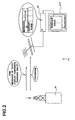
- the digital broadcast system 71 of the present embodiment will be described based on Fig. 2.
- the digital broadcast transmission device 81 transmits programs to each digital broadcast reception device 91, and also transmits commercials thereto. At this time, commercials are transmitted via the digital broadcast system 71 using event messages.
- An event message is made up of a message ID consisting of alphanumeric characters and the like, and output content showing emergency information content.
- the MPEG2 standard is described in ISO/IEC13818-1 and ISO/IEC13818-2.
- DSM-CC standard is described in ISO/IEC13818-6.
- DVB-SI standard is described in ETSI ETS 300 468 (ARIB STD-B10 Version 1.2 in Japan), and BML standard is described in ARIB STD-B24 Version 1.1.
- the generation of the main contents data is the same as the generation of the picture and sounds in the conventional television broadcast system or the generation of web contents in the WWW. Accordingly, a detailed explanation about the generation of the main contents data is omitted.
- the sub contents data means data except the main contents data such as the above-mentioned commercial.
- the commercial is regarded as the sub contents data.
- the event message is used for transmission and reception of the commercial.
- the output contents including the message ID and the contents of the commercial are multiplexed on the usual program.
- Fig. 6 shows an example of the reference table T3 of the message ID and the output form having the above-mentioned data structure.
- the reference table T3 of the message ID and the output form includes blocks b1, b2 , b3,... corresponding to each message ID.
- Message ID "0x01" is used to switch from the display of main contents being displayed on the display device 417 to display sub contents. That is, it is used to interrupt the display of main contents and begin the display of sub contents. Consequently, when a digital broadcast reception device 91 receives a "0x01" message ID it must perform the following actions.
- the "0x02" message ID needs to execute this action on a digital broadcast reception device 91.
- this message ID is written in a message ID table, the following data is stored in block b2: "0x02" is stored in area b11, which corresponds to the output form description portion; “active” is stored in area b13, which corresponds to the display position description portion; “no output” is stored in area b15, which corresponds to the output yes or no description portion; “message ID retrieval time” is stored in area b17, which corresponds to the output time description portion; “- (undefined)” is stored in area b19, which corresponds to the output conditions description portion; “sub contents time stamp” is stored in area b21, which corresponds to the temporary storage data description portion; and “main content” is stored in area b23, which corresponds to the display data location description portion.
- Message ID "0x03" is used to terminate the display of sub contents being displayed on the display device 417, and re-initiate the playback of main contents that was being displayed before. Consequently, when a digital broadcast reception device 91 receives a "0x03" message ID it must perform the following actions.
- Message ID "0x04" is used to terminate the display of main contents and sub contents being displayed on the display device 417. Consequently, when a digital broadcast reception device 91 receives a "0x04" message ID it must perform the following actions.
- the "0x04" message ID needs to execute this action on a digital broadcast reception device 91.
- this message ID is written in a message ID table, the following data is stored in block b4: "0x04" is stored in area b11, which corresponds to the output form description portion; “active” is stored in area b13, which corresponds to the display position description portion; “no output” is stored in area b15, which corresponds to the output yes or no description portion; “message ID retrieval time” is stored in area b17, which corresponds to the output time description portion; “- (undefined)” is stored in area b19, which corresponds to the output conditions description portion; “do not save” is stored in area b21, which corresponds to the temporary storage data description portion; and “none” is stored in area b23, which corresponds to the display data location description portion.
- the "0x05” message ID needs to execute this action on a digital broadcast reception device 91.
- this message ID is written in a message ID table, the following data is stored in block b5: "0x05” is stored in area b11, which corresponds to the output form description portion; “active” is stored in area b13, which corresponds to the display position description portion; “no output” is stored in area b15, which corresponds to the output yes or no description portion; “message ID retrieval time” is stored in area b17, which corresponds to the output time description portion; “- (none)” is stored in area b19, which corresponds to the output conditions description portion; “main contents time stamp” is stored in area b21, which corresponds to the temporary storage data description portion; and "output content from memory” is stored in area b23, which corresponds to the display data location description portion.
- output content is data relating to commercials.
- this data may be a commercial consisting of mixed images and sound, as in conventional television broadcasts, or it may be an image like the banner advertisements contained in Web content. Furthermore, it may also consist solely of text characters made up of text data.
- This type of commercial generation can apply existing commercial generation methods, and so the generation process will be omitted here.
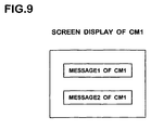
- Fig. 8 shows an example of self description-type data in the case where a commercial is displayed on a display device 417 using the above-mentioned message IDs.
- the content generator writes the message ID to the head portion H3 specified by the ⁇ head ⁇ ... ⁇ /head ⁇ self description-type data tags.
- the message ID is written to the event_msg_id in the event description portion E3 specified by the ⁇ event ⁇ ... ⁇ /event ⁇ tags in the head portion H3.
- the entire script is written, specifying the commercial content - which is the output content - to be displayed in the display area, via the ⁇ html ⁇ ... ⁇ /html ⁇ tags. More specifically, @media: within the ⁇ style ⁇ ... ⁇ /style ⁇ tags describes what type of media to display thereto.
- a commercial is to be displayed on television, so the descriptor is @media:tv.
- #text1 and #text2 specify the position in which text is to be displayed in the commercial. The text to be displayed in the commercial is described within ⁇ body ⁇ ... ⁇ /body ⁇ .
- the CPU 410 of the digital broadcast reception device 91 retrieves a message ID not defined in the reference table T3 of the message ID and output form, it displays the commercial based on the retrieved script. Note that in this case, the script must describe the output form with which to display the commercial on the display device 417.
- Fig. 10 shows a sample script of this type.
- the content generator writes the message ID in the head portion H5 specified by the ⁇ head ⁇ ... ⁇ /head ⁇ self description-type data tags.
- the message ID is written to the event_msg_id in the event description portion E5 specified by the ⁇ event ⁇ ... ⁇ /event ⁇ tags in the head portion H5.
- the output form with which to display the commercial on the display device 417 is defined by the change() function, in the script description portion S5, specified by the ⁇ script ⁇ ... ⁇ /script ⁇ tags.
- the change() function contains a script which opens a new window, and displays the contents of the commercial in that window. Note that a concrete description of the change() function is omitted from Fig. 10.
- CM2 The commercial displayed by this script (hereinafter "CM2") is shown in Fig. 11.
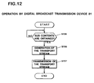
- Fig. 12 shows a flowchart of the operation performed by the CPU 310 of the digital broadcast transmission device 81.
- Fig. 13 shows a flowchart of the operation performed by the CPU 410 of the digital broadcast reception device 91.
- the operation of the CPU 310 of the digital broadcast transmission device 81 will be explained with reference to Fig. 12.
- the contents generator When an commercial is transmitted, the contents generator generates sub contents data for transmitting the commercial, by using the script.
- the generated sub contents data that are described in the script are given to the digital broadcast transmission device 81.
- the CPU 310 decides whether the sub contents data are obtained or not (S703). Until the sub contents data are obtained, it is in the waiting state.
- the decision whether the sub contents data are obtained or not can be replaced with an automatic decision by the digital broadcast transmission device 81. Furthermore, when the sub contents data are obtained, verification that it is the sub contents data can be required to the user so as to decide that the data are obtained when the verification is obtained.
- the CPU 410 decides whether the packets of the transport stream repeatedly transmitted by the broadcasting station in accordance with the transmission rule are received or not (S801). If the packets of the transport stream are not received, the CPU becomes waiting state until it is received.
- the packet that is the object to be selected i.e., the packet that includes sub the contents data
- the packet that includes sub the contents data is selected from the received transport stream in accordance with a predetermined selection condition (S803).
- the selected packet includes a predetermined message ID or not (S805).
- the reference table T3 of the message ID and the output form recorded in the memory 411 of the digital broadcast reception device 91 is referred.
- the output contents data are extracted in accordance with the self description type data included in the packet that has been selected in step S803 (S809). Then, the sub contents data are reconstructed in accordance with the output form that has been extracted in step S807 and the output contents data that have been extracted in step S809 (S811).
- the reconstructed sub contents data are transmitted to the display device 417, so that the sub contents data are displayed on the display device 417.
- step S805 If the predetermined message ID is not received in step S805, the script for displaying the sub contents data is extracted from the self description type data stored in the packet that has been selected in step S803 (S813). Then, the sub contents data are reconstructed in accordance with the extracted script (S811).
- CM1 script script containing message ID "0x01"
- the digital broadcast reception device 91 in each household receives the CM1 script, it extracts the "0x01" message ID therefrom. The device then determines the output form corresponding to message ID "0x01" based on the reference table T3 of the message ID and output form (see Fig. 6) stored in the memory 411.
- CM1 is displayed on the display device 417 based on the determined output form.
- the time stamp (TS1) of program 1 is temporarily stored in a predetermined area of the memory 411.
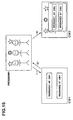
- Fig. 15 The change to the screen of the display device 417 at this time is shown in Fig. 15. As shown by arrow (1), the screen switches from program 1 to CM1.
- the broadcaster uses the digital broadcast transmission device 81 to multiplex the message ID "0x03" into data for the program 1, and sends it to ordinary households.
- the output content is not defined, and the content consists of empty data.
- the digital broadcast reception device 91 in each household receives the "0x03" message ID, the device determines the output form corresponding to message ID "0x03" based on the reference table T3 of the message ID and output form stored in the memory 411.
- output content data was never defined, there was never any data to display. In some cases, output content data may be defined, but with message ID "0x03" no output content data is displayed by the corresponding output form. Then, the program 1 broadcast is resumed, based on the time stamp (TS1) stored in the memory 417, showing the time at which the program was interrupted.
- TS1 time stamp
- CM2 script a script
- the digital broadcast reception device 91 in each household receives the CM2 script, it extracts the "0x01" message ID therefrom. However, the CM2 script does not contain a message ID defined in the reference table T3 of the message ID and output form. So at this time, the digital broadcast reception device 91 extracts the output form from the received CM2 script. The device then displays CM2 on the display device 417 based on the extracted output form. Additionally, the time stamp (TS3) when CM2 is being displayed for program 1, i.e., showing the time at which the program 1, was interrupted is temporarily stored in a predetermined location in the memory 417.
- TS3 time stamp
- the broadcaster uses the digital broadcast transmission device 81 to multiplex message ID "0x02" into data for the program 1, and sends it to ordinary households. At this time, no output content data is recorded.
- the digital broadcast reception device 91 in each household receives the "0x02" message ID, the device determines the output form corresponding to message ID "0x02" based on the reference table T3 of the message ID and output form stored in the memory 411.
- output content data was never defined, there was never any data to be displayed. In some cases, output content data may be defined, but with message ID "0x02" no output content data is displayed by the corresponding output form. Then, the program 1 broadcast is resumed, based on the time stamp (TS3) for the main contents stored in the memory 411.
- TS3 time stamp
- the CM2 data received including CM2's output form, is stored in the memory 411.
- the broadcaster uses the digital broadcast transmission device 81 to multiplex the message ID "0x05" into data for the program 1, and sends it to ordinary households.
- the device When the digital broadcast reception device 91 in each household receives the "0x05" message ID, the device displays CM2 to the display device 417, based on the CM2 data stored in the memory 411 when it was interrupted the previous time.
- the overall constitution of the present embodiment is the same as that of the first embodiment. In the present embodiment, however, the sub contents is emergency information.
- Fig. 17 shows an embodiment of the broadcast system shown in Fig. 1, which is a digital broadcast system 51 including a digital broadcast transmission device 31 and a digital broadcast reception device 41. Before the explanation of the digital broadcast system 51, a digital broadcast will be explained shortly.
- contents of the WWW are generally described in HTML (Hyper Text Markup Language).
- HTML Hyper Text Markup Language
- Such contents described in HTML can handle moving pictures and sounds simultaneously.
- a script language such as JavaScript, an interactive operation can be realized.
- HTML format contents having such characteristics For a digital broadcast system.
- a program and information such as images, sounds or character information related to the program can be dealt with simultaneously.
- the so-called digital multiplex broadcast can be realized by transmitting an HTML format contents about the program and the performers.
- a digital broadcast system in which the transmission side transmits the HTML format contents about the program collectively, and the reception side memorizes the transmitted HTML format contents in a memory can provide an operation of getting data interactively.
- audience can get information about the performers while watching the program, so as to understand the detail of the program or to enjoy the program more. Furthermore, since the interactive operation can be experienced, the system can support various needs of the audiences in detail.
- the digital broadcast transmission device 31 transmits the number to each digital broadcast reception device 41 and transmits emergency information when an emergency situation has occurred.
- the digital broadcast system 51 transmits an event message when transmitting the emergency information.
- the event message consists of a message ID made of numerals and characters and output contents indicating the contents of the emergency information.
- the digital broadcast reception device 41 that has received the event message determines the output form in accordance with the message ID.
- the output form defines rules for displaying the output contents on the display device 417. Then, the output contents are displayed by the display device 417 in accordance with the determined output form.
- the digital broadcast system 51 is to be based on MPEG2 standard, DSM-CC standard, DVB-SI standard and BML standard (the standard related to the data broadcasting in the BS digital broadcasting).
- the MPEG2 standard is described in ISO/IEC13818-1 and ISO/IEC13818-2.
- DSM-CC standard is described in ISO/IEC13818-6.
- DVB-SI standard is described in ETSI ETS 300 468 (ARIB STD-B10 Version 1.2 in Japan), and BML standard is described in ARIB STD-B24 Version 1.1.
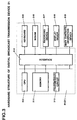
- Fig. 3 shows a hardware structure of the digital broadcast transmission device 31.
- the digital broadcast transmission device 31 includes a CPU 310 for processing operations such as generation of the transport stream or control of each portion, a memory 311, a transmission circuit 313 for transmitting the generated transport stream externally, an interface 314 for controlling the input and the output between the CPU 310 and the external equipment, and a keyboard 315 and a mouse 316 as input means for an operator to input characters and instructions.
- the memory 311 stores a program for controlling the operation of the CPU 310.
- the digital broadcast transmission device 31 is connected to external equipment such as a recording device 317, a display device 318 and a main contents generation device 319.
- the recording device 317 records digital data and may be composed of a hard disk drive or a floppy disk drive.
- the display device 318 displays main contents data and sub contents data.
- the main contents generation device 319 generates main contents and may be a video camera or an image edit device for editing an image obtained by a video camera.
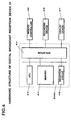
- Fig. 4 shows a hardware structure of the digital broadcast reception device 41.
- the digital broadcast reception device 41 includes a CPU 410 for processing operations such as selection of the transport stream or occasional decision whether a unique event message is transmitted or not, a memory 411 for memorizing a program for controlling the operation of the CPU 410 and for used for working area of the CPU 410, a reception circuit 413 for receiving a transport stream externally and an interface 414 for controlling input and output between the CPU 410 and the external equipment.
- the memory 411 memorizes a program for controlling the operation of the CPU 410 and a reference table of the message ID and the output form that will be explained later.
- the digital broadcast reception device 41 is connected to a remote controller 415, a recording device 416 and a display device 417 as the external equipment.
- the remote controller 415 transmits and receives signals for operating the contents that are displayed on the display device 417.
- the recording device 416 records digital data, and may be a hard disk drive or a floppy disk drive.
- the display device 417 displays at least the main contents data and the sub contents data.
- a transmission side usually transmits programs.
- an emergency situation such as a change of the meteorological information or an event has occurred, an emergency Information is transmitted along with the normal program.
- the transmission of the emergency information is the same in the digital broadcast system. Namely, in the digital broadcast system 51, a program and HTML format contents about the program are usually transmitted. However, when an emergency situation occurs, an emergency information is required to be transmitted along with the normal program and the HTML format contents.
- the main contents data means data to be a heart in the broadcast.
- the above-mentioned program such as dramas, varieties or news
- the HTML format contents correspond the main contents data.
- the generation of the main contents data is the same as the generation of the picture and sounds in the conventional television broadcast system or the generation of web contents in the WWW. Accordingly, a detailed explanation about the generation of the main contents data is omitted.
- the sub contents data means data except the main contents data such as the above-mentioned emergency information.
- the emergency information is regarded as the sub contents data.
- the event message is used for transmission and reception of the emergency information.
- the output contents including the message ID and the contents of the emergency information are multiplexed on the usual program.
- the contents generator of the emergency Information describes the contents in the script format. In this way, by describing the output contents in the script format, the contents generator can generate the contents freely.
- a output form that matches the received message ID is extracted from the reference table of the message ID and the output form.
- the received output contents are displayed in accordance with the extracted output form.
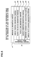
- Fig. 18 shows a data structure of the reference table of the message ID and the output form.
- the message ID table of the conventional event message see Fig.22
- output contents and output form are defined for each message ID.
- the reference table of the message ID and the output form consists of a message ID description portion a1 and an output form description portion a3.
- the output form description portion a3 includes a display position description portion a31 that describes the display position of the sub contents, an output yes or no description portion a33 that describes whether the sub contents are outputted or not, an output time description portion a35 that describes the output time of the sub contents, an output condition description portion a37 that describes the output condition of the sub contents.
- Fig. 19 shows an example of the reference table T1 of the message ID and the output form having the above-mentioned data structure.
- the reference table T1 of the message ID and the output form is memorized in the memory 411 of the digital broadcast reception device 41.
- the the reference table T1 of the message ID and the output form includes blocks b1, b2 , b3,... corresponding to each message ID.
- the output form of the message ID "0x01" is defined as follows.
- the output contents data are displayed "in the area from the start position that is 50 pixels from the upper end and 300 pixels from the left end of the active window by a horizontal width of 400 pixels and a vertical width of 100 pixels.
- the output contents data is “always displayed “. 3 ⁇
- the output time is "not defined “. 4 ⁇
- the effect of the display such as blinking display of the output contents is “not defined.”
- the output form of this message ID "0x01" is described in the message ID table as follows.
- the code “0x01” is described in the area b11 corresponding to the output form description portion of the blocks b1.
- the code “active, 50, 300, 400, 100” is described in the area b13 corresponding to the display position description portion.
- the code “output Yes” is described in the area b15 corresponding to the output yes or no description portion.
- the code "-(not defined)” is described in the area b17 that corresponds to the output time description portion.
- the code “-(not defined)” is described in the area that corresponds to the output condition description portion b19.
- the output contents mean the information displayed within the above-mentioned display area.
- the data is "Meteorological information! Heavy rain and flood warning in southern district of Hyogo.”
- the contents provider generates the sub contents including the message ID and the output contents.
- Fig. 20 shows an example of the sub contents data that are transmitted by the digital broadcast transmission device 31 and are described by the script so as to display the above-mentioned output contents on the display device 417 of the digital broadcast reception device 41.
- the contents provider When the emergency situation occurs, the contents provider generates the sub contents data as shown in Fig. 20.
- the transmission side use the digital broadcast transmission device 31 for multiplexing the sub contents data on the main contents data so as to transmit the resulted data.
- the script shown in Fig. 20 will be explained.
- the contents generator describes the message ID and the output contents at the head portion H1 in the tag ⁇ head ⁇ - ⁇ /head ⁇ of the self description type data.
- the message ID is described at the message_id in the event description portion E1 of the tag ⁇ bevent ⁇ - ⁇ /bevent ⁇ in the head portion H1.
- an event_handler1 function is defined in the script description portion S1 of the tag ⁇ script ⁇ - ⁇ /script ⁇ .
- message IDs were sent together with commercial data, which is output content data. It may be possible, however, to first send all commercial data scheduled for broadcast in a single batch transmission, and store them in the memory 411 of the digital broadcast reception device 91. In this case, the output forms are also included with the data, in order to specify the commercial data to be displayed. Based on this data, the digital broadcast reception device 91 retrieves the specified items from the commercial data stored in the memory 411.
- the data structure of output forms in the reference table T3 of the message ID and output form had an output form description portion a3, a display position description portion a31, an output yes or no description portion a33, an output time description portion a35, an output condition description portion a37, a temporary storage data description portion a39, and a display data location description portion a41.
- the embodiments are not limited to this example. The same holds for the second embodiment.
- the output content of the sub contents in the above-mentioned first embodiment was commercials, the embodiments are not limited to this example. It is also possible for the output content to be a different program from the one currently being broadcast.
- the main contents were programs and program-related content in HTML format, and the like, and the sub contents was described as emergency information.
- the embodiments are not limited to this. Anything is permissible, as long as the main contents data and sub contents data can be multiplexed, and a transport stream can be generated.
- the data structure of output form had an output form description portion a3, a display position description portion a31, an output yes or no description portion a33, an output time description portion a35, and an output condition description portion a37.
- the embodiments are not limited to this example.
- emergency information when displaying emergency information, it is possible to define such parameters as background images, background colors, text font and formatting, and the like. It is also possible to specify sounds to be played in coordination with the sub contents. For example, in the case of emergency information, it is possible to add attention-getting sounds, and in the case of a news flash for professional baseball or the like, it is permissible to add fanfare sounds, and the like.
- the data structure of the output form had an output form description portion a3, a display position description portion a31, an output yes or no description portion a33, an output time description portion a35, and an output condition description portion a37.
- this structure it is permissible for this structure to have a portion of these.
- the broadcast system of the present invention will be effective as a broadcast system which displays emergency information, and as a broadcast system which switches between programs and advertisements, and is especially suited to use as a broadcast system which generates transport streams by multiplexing main contents and sub contents.
Landscapes
- Engineering & Computer Science (AREA)
- Multimedia (AREA)
- Signal Processing (AREA)
- Business, Economics & Management (AREA)
- Emergency Management (AREA)
- Marketing (AREA)
- Computer Graphics (AREA)
- Television Systems (AREA)
- Circuits Of Receivers In General (AREA)
- Two-Way Televisions, Distribution Of Moving Picture Or The Like (AREA)
Abstract
A digital broadcast transmission device 31 sends
programs to respective digital broadcast reception devices
41, and also sends emergency information thereto in the
case of an emergency. In the event of a transmission of
emergency information, the digital broadcast system 51
sends an event message. An event message is made up of a
message ID consisting of alphanumeric characters and the
like, and output content showing emergency information
content. When a digital broadcast reception device 41
receives an event message, the device determines the output
form based on the message ID. Output forms are prescribed
formats for displaying output content on a display device
417. Output content is displayed on the display device 417
based on the determined output form.
Description
The present invention relates to a broadcast system,
more specifically to generation and reconstruction of a
transport stream.
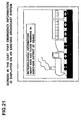
When watching television, a meteorological
information or an earthquake information may appear
suddenly (see Fig. 21). In the broadcast system such as a
television, there is a method for displaying an emergency
information such as a meteorological information on the
screen of the television set utilizing a message ID. The
emergency broadcast using the message ID will be explained
below.
First, all contents that are assumed for the
emergency information are listed. Concerning each of the
emergency information, it is determined where on the screen
the emergency information is to be displayed. Numbering is
performed for a set of contents of the emergency
information and the display position on the screen. This
number is a message ID. An example of a message ID table
showing the relationship among the message ID, the display
position and the contents are shown in Fig. 22.
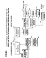
With reference to Fig. 23, it will be explained how
the emergency information using the message ID is displayed
on the screen of the television set. A contents provider
transmits a message ID as the emergency information by an
emergency information transmission device 201 when an
emergency situation occurs. In an emergency information
multiplex device 203, a video signal obtained by a TV
program transmission device 204 and the message ID are
multiplexed so as to send them to a TV transmitter 205.
The TV transmitter 205 transmits the video signal and the
message ID.
Each TV receiver receives the signal by the RF
reception portion 206 and sends the signal to the video
demodulation portion 207. The video demodulation portion
207 demodulates the video signal from the received signal.
In addition, a color signal demodulation portion 208
demodulates a color information.
On the other hand, an emergency information process
portion 209 extracts the message ID from the received
signal. The extracted message ID is compared with a
memorized message ID table, so as to extract characters to
be displayed (e.g., "meteorological information ") and a
output form from the message ID table. A character
generation portion 210 generates a video signal related to
the characters extracted by the emergency information
processing portion 209. In addition, an electronic sound
generator 211 generates an atmos that is used when
displaying the characters in accordance with the extracted
output form.
The characters generated by the character generation
portion and the picture of the program are memorized in a
display memory 212. Then, a switching mixer 213 switches a
picture with an emergency Information and a normal program
picture.
The above-mentioned emergency broadcast utilizing a
message ID has some problems as follows.
The message ID is set for each of the emergency
information that is assumed considering the display
position and the output contents. In addition, concerning
the particularly important emergency Information, adding to
the display position, a display method such as a sound with
the display or a blink display should be considered, so as
to arrest audience's attention.
When setting the message ID, the more the above-mentioned
points to be considered, the more the number of
the message ID becomes.
In addition, since the contents of the emergency
information is determined corresponding to the message ID,
it is difficult to support promptly for an unexpected
emergency situation.
Furthermore, as the content of the emergency
information output is pre-determined corresponding to the
message ID, it is necessary to store the output content
data. Normally, the memory capacity for storing the output
content is not large. Consequently, the type of output
content that can be stored is limited to types of data that
do not take up a great deal of space, such as text.
An object of the present invention is to provide a
broadcast system which is capable of displaying the output
content of the sub contents, without annotating the sub
contents with output form-related script in order to
display the output content on the screen.
An object of the present invention is to provide a
broadcast system that can support any type of information
display with fewer messages IDs.
In this invention, a transmission device generates
sub contents data including an output form ID that
indicates an output form of sub contents and output
contents data that indicate output contents, generates a
transport stream by multiplexing at least main contents
data and the sub contents data, and transmits the generated
transport stream. A reception device receives the
transport stream transmitted by the transmission device,
determining the output form of the sub contents data in
accordance with the output form that is predetermined for
the output form ID in the received sub contents data, and
determining the output contents of the sub contents data in
accordance with the output contents data in the received
sub contents data, so as to perform the reconstruction
control of the sub contents data, and controls
reconstruction of the main contents in accordance with the
received transport stream.
Thus, it is possible to reconstruct the output
contents of the sub contents, without writing an output
form-related script in the sub contents in order to display
the output contents on the screen. Thus, a plurality of
output contents data can correspond to one output form ID.
In this invention, sub contents data are generated
that include an output form ID that indicates an output
form of the sub contents as well as an output contents data
that indicate an output contents, and a transport stream is
generated by multiplexing at least main contents data and
the sub contents data.
Thus, sub contents can be generated in which a
plurality of output contents data corresponds to one output
form ID.
In this invention, a transport stream transmitted by
a transmission device is received, the output form of the
sub contents data is determined in accordance with the
output form that is predetermined for the output form ID in
the received sub contents data, and the output contents of
the sub contents data are determined in accordance with the
output contents data in the received sub contents data, so
as to control the reconstruction of the sub contents data.
Thus, sub contents can be reconstructed in which a
plurality of output contents data corresponds to one output
form ID.
In this invention, an output form table describing
the output form ID and the output form corresponding
thereto is recorded.
Thus, an output form corresponding to the output form
ID can be obtained easily.
In this invention, the output form includes at least
a display position of the sub contents.
Thus, the relationship between the output form ID and
the display position can be predetermined. Accordingly, by
determining the output form ID, the display position is
also determined.
In this invention, the output form includes at least
information about whether the sub contents are outputted or
not.
Thus, the relationship between the output form ID and
the information about whether the sub contents are
outputted or not can be predetermined. Accordingly, if the
output form ID is determined, whether the sub contents are
outputted or not is also determined.
In this invention, the output form includes at least
an output time of the sub contents.
Thus, the relationship between the output form ID and
the output time of the sub contents can be predetermined.
Accordingly, if the output form ID is determined, the
output time of the sub contents is also determined.
In this invention, the output form includes at least
an output condition of the sub contents.
Thus, relationship between the output form ID and the
output condition of the sub contents can be predetermined.
Accordingly, if the output form ID is determined, the
output condition of the sub contents is also determined.
In this invention, the reception device determines
the output form of the sub contents in accordance with a
predetermined output form when the received output form ID
is not a predetermined one.
Thus, even if an output form ID that is not
predetermined is received, the output form of the sub
contents can be determined securely.
In this invention, the sub contents are commercial.
Thus, the output form of the commercial can be specified by
the output form ID.
In this invention, sub contents are emergency
information. Thus, output form of the emergency information
can be specified by the output form ID.
Contents data according to this invention are
contents data in which main contents data and sub contents
data are multiplexed, and the sub contents data include an
output form ID that indicates an output form of the sub
contents and output contents data that indicate output
contents.
Thus, the output form can be specified by the output
form ID, so that the sub contents data can be generated
easily.
In a reconstruction program according to this
invention, the output form of the sub contents data is
determined in accordance with a predetermined output form
for an output form ID in the sub contents data, and output
contents of the sub contents data are determined in
accordance with output contents data in the sub contents
data, so as to perform reconstruction control of the sub
contents data.
Thus, a plurality of output contents data can
correspond to one output form ID.
A data structure according to this invention includes
an output form description portion that describes an output
form and an output form ID description portion that
describes an output form ID corresponding to the output
form described in the output form description portion.
Thus, only by specifying the output form ID the
output form can be determined.
The multiplex portion executes the operation of step
S705 and step S707 of the flowchart shown in Fig. 12. In
addition, the reconstruction portion executes the operation
of step S803-S811 of the flowchart shown in Fig. 13.
The relationship between the elements specified in
the claims and the elements described in the embodiments
are as follows. The transmission device corresponds to a
digital broadcast transmission device 31. The reception
device corresponds to a digital broadcast reception device
41. The multiplex portion corresponds to a CPU 310. The
transmission portion corresponds to a transmission circuit
313. The reception portion corresponds to a reception
circuit 413. The reconstruction portion corresponds to a
CPU 410.
Furthermore, the output form ID corresponds to a
message ID, and the output contents data corresponds to
emergency information and commercial-related data.
The output form table corresponds to the reference
table T1, T3 of the message ID and output form. The output
form description portion corresponds to an output form
description portion a3, and the output form ID description
portion corresponds to a message ID description portion a1.
Fig. 1 is a functional block diagram of a broadcast
system according to a first embodiment of the present
invention. A broadcast system 1 includes a transmission
device 3 and a reception device 5.
The transmission device 3 includes a multiplex
portion 11 and a transmission portion 13. The reception
device 5 includes a reception portion 15 and a
reconstruction portion 17.
The multiplex portion 11 multiplies at least main
contents data and sub contents data so as to generate a
transport stream. The transmission portion 13 transmits
the transport stream generated by the multiplex portion 11.
The reception portion 15 receives the transport
stream transmitted by the transmission device 3. The
reconstruction portion 17 determines an output form of the
sub contents data in accordance with the output form that
is predetermined for the output form ID in the received sub
contents data and determines the output contents of the sub
contents data in accordance with the output contents data
in the received sub contents data, so as to perform the
reconstruction control of the sub contents data.
In addition, an output form table describing the
output form ID and the output form corresponding thereto is
recorded in the reception device 5. Furthermore, the
reception device 5 determines the output form of the sub
contents in accordance with a predetermined output form
when the received output form ID is not a predetermined one.
In addition, sub contents are emergency information.
The output form includes at least display position of
the sub contents. Furthermore, the output form includes at
least information about whether the sub contents are
outputted or not. In addition, the output form includes at
least an output time of the sub contents. In addition, the
output form includes at least an output condition of the
sub contents.
In addition, the reception device 5 determines the
output form of the sub contents in accordance with a
predetermined output form when the received output form ID
is not a predetermined one.
Thus, a plurality of output contents data can be
assigned to one output form ID.
Fig. 2 shows an embodiment of the broadcast system
shown in Fig. 1, which is a digital broadcast system 71
including a digital broadcast transmission device 81 and a
digital broadcast reception device 91. Before the
explanation of the digital broadcast system 71, a digital
broadcast will be explained shortly.
At present, contents of the WWW (World Wide Web) are
generally described in HTML (Hyper Text Markup Language).
Such contents described in HTML (hereinafter, referred to
as HTML format contents) can handle moving pictures and
sounds simultaneously. In addition, using a script
language such as JavaScript, an interactive operation can
be realized.
It is studied to utilize the HTML format contents
having such characteristics for a digital broadcast system.
In this way, a program and information such as images,
sounds or character information related to the program can
be dealt with simultaneously. For example, the so-called
digital multiplex broadcast can be realized by transmitting
an HTML format contents about the program and the
performers.
Furthermore, a digital broadcast system in which the
transmission side transmits the HTML format contents about
the program collectively, and the reception side memorizes
the transmitted HTML format contents in a memory can
provide an operation of getting data interactively.
By utilizing the digital broadcast, audiences can get
information about the performers while watching the program,
so as to understand the detail of the program or to enjoy
the program more. Furthermore, since the interactive
operation can be experienced, the system can support
various needs of the audiences in detail.
The digital broadcast system 71 of the present
embodiment will be described based on Fig. 2. The digital
broadcast transmission device 81 transmits programs to each
digital broadcast reception device 91, and also transmits
commercials thereto. At this time, commercials are
transmitted via the digital broadcast system 71 using event
messages.
An event message is made up of a message ID
consisting of alphanumeric characters and the like, and
output content showing emergency information content.
When a digital broadcast reception device 91 receives
an event message, the device determines the output form
based on the message ID, then displays a commercial on a
display device 417 based on the determined output form.
Thus, it is possible to switch between programs and
commercials by sending and receiving commercials using
event messages.
Hereinafter, the digital broadcast system 71 will be
explained in detail. The digital broadcast system 71 is to
be based on MPEG2 standard, DSM-CC standard, DVB-SI
standard and BML standard (the standard related to the data
broadcasting in the BS digital broadcasting).
The MPEG2 standard is described in ISO/IEC13818-1 and
ISO/IEC13818-2. DSM-CC standard is described in
ISO/IEC13818-6. Furthermore, DVB-SI standard is described
in ETSI ETS 300 468 (ARIB STD-B10 Version 1.2 in Japan),
and BML standard is described in ARIB STD-B24 Version 1.1.
Fig. 3 shows a hardware structure of the digital
broadcast transmission device 81. The digital broadcast
transmission device 81 includes a CPU 310 for processing
operations such as generation of the transport stream or
control of each portion, a memory 311 for used for working
area of the CPU 310, a transmission circuit 313 for
transmitting the generated transport stream externally, an
interface 314 for controlling the input and the output
between the CPU 310 and the external equipment, and a
keyboard 315 and a mouse 316 as input means for an operator
to input characters and instructions. The memory 311
stores a program for controlling the operation of the CPU
310.
The digital broadcast transmission device 81 is
connected to external equipment such as a recording device
317, a display device 318 and a main contents generation
device 319. The recording device 317 records digital data
and may be composed of a hard disk drive or a floppy disk
drive. The display device 318 displays main contents data
and sub contents data. The main contents generation device
319 generates main contents and may be a video camera or an
image edit device for editing an image obtained by a video
camera.
Fig. 4 shows a hardware structure of the digital
broadcast reception device 91. The digital broadcast
reception device 91 includes a CPU 410 for processing
operations such as selection of the transport stream or
occasional decision whether a unique event message is
transmitted or not, a memory 411 for memorizing a program
for controlling the operation of the CPU 410 and for used
for working area of the CPU 410, a reception circuit 413
for receiving a transport stream externally and an
interface 414 for controlling input and output between the
CPU 410 and the external equipment. The memory 411
memorizes a program for controlling the operation of the
CPU 410 and a reference table T3 of the message ID and the
output form that will be explained later.
The digital broadcast reception device 91 is
connected to a remote controller 415, a recording device
416 and a display device 417 as the external equipment.
The remote controller 415 transmits and receives signals
for operating the contents that are displayed on the
display device 417. The recording device 416 records
digital data, and may be a hard disk drive or a floppy disk
drive. The display device 417 displays at least the main
contents data and the sub contents data.
Hereinafter, the main contents data and the sub
contents data will be explained.
The main contents data means data to be a heart in
the broadcast. For example, the above-mentioned program
(such as dramas, varieties or news) or the HTML format
contents correspond the main contents data.
The generation of the main contents data is the same
as the generation of the picture and sounds in the
conventional television broadcast system or the generation
of web contents in the WWW. Accordingly, a detailed
explanation about the generation of the main contents data
is omitted.
The sub contents data means data except the main
contents data such as the above-mentioned commercial.
In this embodiment, the commercial is regarded as the
sub contents data. The event message is used for
transmission and reception of the commercial. When the
commercial is transmitted, the output contents including
the message ID and the contents of the commercial are
multiplexed on the usual program.
Concerning the output contents, the contents
generator of the commercial describes the contents in the
script format. In this way, by describing the output
contents in the script format, the contents generator can
generate the contents freely.
On the other hand, when the commercial is received, a
output form that matches the received message ID is
extracted from the reference table T3 of the message ID and
the output form. The received output contents are
displayed in accordance with the extracted output form.
Hereinafter, the message ID and the script will be
explained.
Fig. 5 shows a data structure of the reference table
of the message ID and the output form memorized in the
memory 411. In the message ID table of the conventional
event message (see Fig. 22), output contents and output
form are defined for each message ID.
However, in the reference table of the message ID and the
output form of the event message of this embodiment, only a
output form is defined for each message ID.
The reference table of the message ID and the output
form consists of a message ID description portion a1 and an
output form description portion a3. The output form
description portion a3 includes a display position
description portion a31 that describes the display position
of the sub contents, an output yes or no description
portion a33 that describes whether the sub contents are
outputted or not, an output time description portion a35
that describes the output time of the sub contents, an
output condition description portion a37 that describes the
output condition of the sub contents, and a temporary
storage data description portion a39 that indicates what
data is to be temporarily stored in the memory 411, as well
as a display data location description portion a41 that
indicates what data is to be output.
Fig. 6 shows an example of the reference table T3 of
the message ID and the output form having the above-mentioned
data structure. The reference table T3 of the
message ID and the output form includes blocks b1, b2 ,
b3,... corresponding to each message ID.
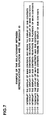
Here, an example of the relationship between
representative situations in which each message ID is used
and the message ID is shown in Fig. 7.
Message ID "0x01" is used to switch from the display
of main contents being displayed on the display device 417
to display sub contents. That is, it is used to interrupt
the display of main contents and begin the display of sub
contents. Consequently, when a digital broadcast reception
device 91 receives a "0x01" message ID it must perform the
following actions.
"When the message ID is retrieved", "the current time
stamp of the main contents (data indicating the amount of
time played from the beginning of the content)" is
temporarily stored in the memory 411, and "the output
content data of the received sub contents" is output to
"the window active at that time" "without adding" any
flashing or other effects to the output content.
The "0x01" message ID needs to execute this action on
a digital broadcast reception device 91. When this message
ID is written in a message ID table, the following data is
stored in block b1: "0x01" is stored in area b11, which
corresponds to the output form description portion;
"active" is stored in area b13, which corresponds to the
display position description portion; "output" is stored in
area b15, which corresponds to the output yes or no
description portion; "message ID retrieval time" is stored
in area b17, which corresponds to the output time
description portion; "- (none)" is stored in area b19,
which corresponds to the output conditions description
portion; "main contents time stamp" is stored in area b21,
which corresponds to the temporary storage data description
portion; and "received output content" is stored in area
b23, which corresponds to the display data location
description portion.
Below, the message IDs "0x02," "0x03," "0x04," and
"0x05" shown in Fig. 12 will be described in the same
manner. Message ID "0x02" is used to interrupt the display
of sub contents being displayed on the display device 417,
and re-initiate the playback of main contents that was
being displayed previously. Consequently, when a digital
broadcast reception device 91 receives a "0x02" message ID
it must perform the following actions.
"When the message ID is retrieved", "the current time
stamp of the sub contents in the memory 411" is temporarily
stored, and "the main content" is "output" to "the window
active at that time" based on the time stamp stored in the
memory 411 indicating the last interrupt time "without
adding" any flashing or other effects to the output content.
The "0x02" message ID needs to execute this action on
a digital broadcast reception device 91. When this message
ID is written in a message ID table, the following data is
stored in block b2: "0x02" is stored in area b11, which
corresponds to the output form description portion;
"active" is stored in area b13, which corresponds to the
display position description portion; "no output" is stored
in area b15, which corresponds to the output yes or no
description portion; "message ID retrieval time" is stored
in area b17, which corresponds to the output time
description portion; "- (undefined)" is stored in area b19,
which corresponds to the output conditions description
portion; "sub contents time stamp" is stored in area b21,
which corresponds to the temporary storage data description
portion; and "main content" is stored in area b23, which
corresponds to the display data location description
portion.
Message ID "0x03" is used to terminate the display of
sub contents being displayed on the display device 417, and
re-initiate the playback of main contents that was being
displayed before. Consequently, when a digital broadcast
reception device 91 receives a "0x03" message ID it must
perform the following actions.
"When the message ID is retrieved", the display of
sub contents is terminated, and "the main content" is
"output" to "the window active at that time" based on the
main contents time stamp stored in the memory 411 "without
adding" any flashing or other effects to the output content.
The "0x03" message ID needs to execute this action on
a digital broadcast reception device 91. When this message
ID is written in a message ID table, the following data is
stored in block b3: "0x03" is stored in area b11, which
corresponds to the output form description portion;
"active" is stored in area b13, which corresponds to the
display position description portion; "no output" is stored
in area b15, which corresponds to the output yes or no
description portion; "message ID retrieval time" is stored
in area b17, which corresponds to the output time
description portion; "- (undefined)" is stored in area b19,
which corresponds to the output conditions description
portion; "do not save" is stored in area b21, which
corresponds to the temporary storage data description
portion; and "main content" is stored in area b23, which
corresponds to the display data location description
portion.
Message ID "0x04" is used to terminate the display of
main contents and sub contents being displayed on the
display device 417. Consequently, when a digital broadcast
reception device 91 receives a "0x04" message ID it must
perform the following actions.
"When the message ID is retrieved", the display of
content to "the window active at that time" is terminated.
The "0x04" message ID needs to execute this action on
a digital broadcast reception device 91. When this message
ID is written in a message ID table, the following data is
stored in block b4: "0x04" is stored in area b11, which
corresponds to the output form description portion;
"active" is stored in area b13, which corresponds to the
display position description portion; "no output" is stored
in area b15, which corresponds to the output yes or no
description portion; "message ID retrieval time" is stored
in area b17, which corresponds to the output time
description portion; "- (undefined)" is stored in area b19,
which corresponds to the output conditions description
portion; "do not save" is stored in area b21, which
corresponds to the temporary storage data description
portion; and "none" is stored in area b23, which
corresponds to the display data location description
portion.
Message ID "0x05" is used to switch from the display
of main contents being displayed on the display device 417,
to display previously received sub contents. That is, it is
used to interrupt the display of main contents and resume
the display of sub contents that had been previously
received. Consequently, when a digital broadcast reception
device 91 receives a "0x05" message ID it must perform the
following actions.
"When the message ID is retrieved", "the current time
stamp of the main content" is temporarily stored in the
memory 411, and "the output content data of the sub
contents stored in the memory 411" is output to "the window
active at that time" "without adding" any flashing or other
effects to the output content.
The "0x05" message ID needs to execute this action on
a digital broadcast reception device 91. When this message
ID is written in a message ID table, the following data is
stored in block b5: "0x05" is stored in area b11, which
corresponds to the output form description portion;
"active" is stored in area b13, which corresponds to the
display position description portion; "no output" is stored
in area b15, which corresponds to the output yes or no
description portion; "message ID retrieval time" is stored
in area b17, which corresponds to the output time
description portion; "- (none)" is stored in area b19,
which corresponds to the output conditions description
portion; "main contents time stamp" is stored in area b21,
which corresponds to the temporary storage data description
portion; and "output content from memory" is stored in area
b23, which corresponds to the display data location
description portion.
In this way, message IDs and their corresponding
output forms are stored in the reference table T3 of the
message ID and output form. Note that the reference table
T3 of the message ID and output form is stored in memory
411 of the digital broadcast reception device 91.
With regard to the present embodiment, output content
is data relating to commercials. For example, this data
may be a commercial consisting of mixed images and sound,
as in conventional television broadcasts, or it may be an
image like the banner advertisements contained in Web
content. Furthermore, it may also consist solely of text
characters made up of text data. This type of commercial
generation can apply existing commercial generation methods,
and so the generation process will be omitted here.
Fig. 8 shows an example of self description-type data
in the case where a commercial is displayed on a display
device 417 using the above-mentioned message IDs. The
content generator writes the message ID to the head portion
H3 specified by the 〈head〉 ... 〈/head〉 self description-type
data tags.
The message ID is written to the event_msg_id in the
event description portion E3 specified by the 〈event〉 ...
〈/event〉 tags in the head portion H3.
Additionally, the entire script is written,
specifying the commercial content - which is the output
content - to be displayed in the display area, via the
〈html〉 ... 〈/html〉 tags. More specifically, @media: within
the 〈style〉 ... 〈/style〉 tags describes what type of media
to display thereto. In Fig. 8, a commercial is to be
displayed on television, so the descriptor is @media:tv.
#text1 and #text2 specify the position in which text is to
be displayed in the commercial. The text to be displayed
in the commercial is described within 〈body〉 ... 〈/body〉.
The commercial displayed by this script (hereinafter
"CM1") is shown in Fig. 9.
The present embodiment is a broadcast system capable
of displaying a commercial even with an output form not
defined in the reference table T3 of the message ID and
output form.
In order to display a commercial in an output form
not defined with a message ID in the reference table T3 of
the message ID and output form, a script containing a
message ID not defined in the reference table T3 of the
message ID and output form is sent from the broadcaster.
When the CPU 410 of the digital broadcast reception
device 91 retrieves a message ID not defined in the
reference table T3 of the message ID and output form, it
displays the commercial based on the retrieved script.
Note that in this case, the script must describe the output
form with which to display the commercial on the display
device 417.
Fig. 10 shows a sample script of this type. The
content generator writes the message ID in the head portion
H5 specified by the 〈head〉 ... 〈/head〉 self description-type
data tags.
The message ID is written to the event_msg_id in the
event description portion E5 specified by the 〈event〉 ...
〈/event〉 tags in the head portion H5.
Additionally, the entire script is written,
specifying the commercial - which is the output content -
to be displayed in the display area, via the 〈html〉 ...
〈/html〉 tags. More specifically, @media: within the
〈style〉 ... 〈/style〉 tags describes what type of media to
display. In Fig. 10, a commercial is to be displayed on
television, so the descriptor is @media:tv. #text1 and
#text2 specify the position in which text is to be
displayed in the commercial. The text to be displayed in
the commercial is written within 〈body〉 ... 〈/body〉.
Furthermore, the output form with which to display
the commercial on the display device 417 is defined by the
change() function, in the script description portion S5,
specified by the 〈script〉 ... 〈/script〉 tags. In the
present embodiment, the change() function contains a script
which opens a new window, and displays the contents of the
commercial in that window. Note that a concrete
description of the change() function is omitted from Fig.
10.
The commercial displayed by this script (hereinafter
"CM2") is shown in Fig. 11.
Next, the operation of the digital broadcast
transmission device 81 having the above-mentioned structure
and the digital broadcast reception device 91 will be
explained. Fig. 12 shows a flowchart of the operation
performed by the CPU 310 of the digital broadcast
transmission device 81. Fig. 13 shows a flowchart of the
operation performed by the CPU 410 of the digital broadcast
reception device 91.
The operation of the CPU 310 of the digital broadcast
transmission device 81 will be explained with reference to
Fig. 12. When an commercial is transmitted, the contents
generator generates sub contents data for transmitting the
commercial, by using the script. The generated sub
contents data that are described in the script are given to
the digital broadcast transmission device 81. The CPU 310
decides whether the sub contents data are obtained or not
(S703). Until the sub contents data are obtained, it is in
the waiting state.
The decision whether the sub contents data are
obtained or not can be replaced with an automatic decision
by the digital broadcast transmission device 81.
Furthermore, when the sub contents data are obtained,
verification that it is the sub contents data can be
required to the user so as to decide that the data are
obtained when the verification is obtained.
When the sub contents data are obtained, the main
contents data that are being transmitted and the obtained
sub contents data are multiplexed so as to generate the
transport stream (S705). Then, the generated transport
stream is transmitted (S707). When the transport stream is
transmitted to each home finally, the transport stream is
made into packets. Furthermore, the packets of transport
stream are transmitted in accordance with a transmission
protocol defined in the digital broadcast.
Next, the operation of the CPU 410 of the digital
broadcast reception device 91 will be explained with
reference to Fig. 13. The CPU 410 decides whether the
packets of the transport stream repeatedly transmitted by
the broadcasting station in accordance with the
transmission rule are received or not (S801). If the
packets of the transport stream are not received, the CPU
becomes waiting state until it is received.
If the packets of the transport stream are received,
the packet that is the object to be selected (i.e., the
packet that includes sub the contents data) is selected
from the received transport stream in accordance with a
predetermined selection condition (S803).
It is decided whether the selected packet includes a
predetermined message ID or not (S805). For this decision,
the reference table T3 of the message ID and the output
form recorded in the memory 411 of the digital broadcast
reception device 91 is referred.
If the predetermined message ID is included, the
output form that corresponds to the message ID Is extracted
from the reference table T3 of the message ID and the
output form (S807).
In addition, the output contents data are extracted
in accordance with the self description type data included
in the packet that has been selected in step S803 (S809).
Then, the sub contents data are reconstructed in accordance
with the output form that has been extracted in step S807
and the output contents data that have been extracted in
step S809 (S811).
After that, the reconstructed sub contents data are
transmitted to the display device 417, so that the sub
contents data are displayed on the display device 417.
If the predetermined message ID is not received in
step S805, the script for displaying the sub contents data
is extracted from the self description type data stored in
the packet that has been selected in step S803 (S813).
Then, the sub contents data are reconstructed in accordance
with the extracted script (S811).
Next is given an actual example of how to switch
between a program and a commercial, making reference a case
1 as shown in Fig. 14.
Assume that program 1, which is the main content, is
already being broadcast at time t=t0. In the case that the
broadcaster attempts to broadcast CM1 as the output content
data in the sub contents at time t=t1, the broadcaster uses
the digital broadcast transmission device 81 to multiplex
the script containing message ID "0x01" (hereinafter, "CM1
script") into data for the program 1, and sends it to
ordinary households.
When the digital broadcast reception device 91 in
each household receives the CM1 script, it extracts the
"0x01" message ID therefrom. The device then determines
the output form corresponding to message ID "0x01" based on
the reference table T3 of the message ID and output form
(see Fig. 6) stored in the memory 411.
CM1 is displayed on the display device 417 based on
the determined output form. In addition, at the time when
CM1 is displayed, the time stamp (TS1) of program 1 is
temporarily stored in a predetermined area of the memory
411.
The change to the screen of the display device 417 at
this time is shown in Fig. 15. As shown by arrow (1), the
screen switches from program 1 to CM1.
In the case that the broadcaster attempts to
terminate the broadcast of CM1 as the output content data
in the sub contents at time t=t2, the broadcaster uses the
digital broadcast transmission device 81 to multiplex the
message ID "0x03" into data for the program 1, and sends it
to ordinary households. At this time, the output content
is not defined, and the content consists of empty data.
When the digital broadcast reception device 91 in
each household receives the "0x03" message ID, the device
determines the output form corresponding to message ID
"0x03" based on the reference table T3 of the message ID
and output form stored in the memory 411.
Since the output content data was never defined,
there was never any data to display. In some cases, output
content data may be defined, but with message ID "0x03" no
output content data is displayed by the corresponding
output form. Then, the program 1 broadcast is resumed,
based on the time stamp (TS1) stored in the memory 417,
showing the time at which the program was interrupted.
Note that while CM1 is being broadcast, the data for
program 1 is being delivered, and the digital broadcast
reception device 91 is receiving this data. This data is
stored in a predetermined location of the memory 411. When
the halt on program 1 is released, and its broadcast is
resumed, data for the program 1 stored in the memory 411 is
used therefor.
The change to the screen of the display device 417 at
this time is shown in Fig. 15. As shown by arrow (2), the
screen switches from CM1 to program 1.
Here is examined the case where the broadcaster
attempts to broadcast a new CM2 as the output content data
in the sub contents at time t=t3. Note that this example
will assume that CM2 will not be displayed with an output
form defined by a message ID, and that instead it will be
displayed with another output form.
Furthermore, it will be assumed that the broadcaster
displays CM2 in a separate window from the one in which
program 1 is being displayed. In this case, the
broadcaster uses the digital broadcast transmission device
81 to multiplex a script (hereinafter "CM2 script") into
data for the program 1, and sends it to ordinary households.
When the digital broadcast reception device 91 in
each household receives the CM2 script, it extracts the
"0x01" message ID therefrom. However, the CM2 script does
not contain a message ID defined in the reference table T3
of the message ID and output form. So at this time, the
digital broadcast reception device 91 extracts the output
form from the received CM2 script. The device then
displays CM2 on the display device 417 based on the
extracted output form. Additionally, the time stamp (TS3)
when CM2 is being displayed for program 1, i.e., showing
the time at which the program 1, was interrupted is
temporarily stored in a predetermined location in the
memory 417.
The change to the screen of this display device 417
at this time is shown in Fig. 15. As shown by arrow (3),
the screen switches from program 1 to CM2, which is
displayed in a different window from the program 1.
In the case that the broadcaster attempts to
temporarily interrupt the broadcast of CM2 at time t=t4, as
with the case of terminating CM1, the broadcaster uses the
digital broadcast transmission device 81 to multiplex
message ID "0x02" into data for the program 1, and sends it
to ordinary households. At this time, no output content
data is recorded.
When the digital broadcast reception device 91 in
each household receives the "0x02" message ID, the device
determines the output form corresponding to message ID
"0x02" based on the reference table T3 of the message ID
and output form stored in the memory 411.
Since the output content data was never defined,
there was never any data to be displayed. In some cases,
output content data may be defined, but with message ID
"0x02" no output content data is displayed by the
corresponding output form. Then, the program 1 broadcast
is resumed, based on the time stamp (TS3) for the main
contents stored in the memory 411.
At this time, the CM2 data received, including CM2's
output form, is stored in the memory 411.
The change to the screen of this display device 417
at this time is shown in Fig. 16. As shown by arrow (5),
the screen switches from CM2, which had been displayed in a
separate window from the program 1, to the program 1.
Assume that the broadcaster attempts to resume the
broadcast of CM2, which had been interrupted, at time t=t5.
In this case, the broadcaster uses the digital broadcast
transmission device 81 to multiplex the message ID "0x05"
into data for the program 1, and sends it to ordinary
households.
When the digital broadcast reception device 91 in
each household receives the "0x05" message ID, the device
displays CM2 to the display device 417, based on the CM2
data stored in the memory 411 when it was interrupted the
previous time.
The change to the screen of this display device 417
at this time is shown in Fig. 16. As shown by arrow (4),
the screen switches from the program 1 to CM2, in a
separate window from that of the program 1.
Then when message ID "0x04" is received, the display
of CM2 is terminated, as well as the data broadcast, based
on the reference table T3 of the message ID and output form
(see Fig. 16, arrow (6)).
These actions allow the digital broadcast system 71
to control two states: it can refer to commercials during
programs, via the message ID types, and it is possible to
run scripts in accordance with the content description.
This makes it possible to reduce the processing load on the
CPU.
Furthermore, during content creation it is possible
to realize outstanding functions without any need for the
support of authoring tools.
The overall constitution of the present embodiment is
the same as that of the first embodiment. In the present
embodiment, however, the sub contents is emergency
information.
Fig. 17 shows an embodiment of the broadcast system
shown in Fig. 1, which is a digital broadcast system 51
including a digital broadcast transmission device 31 and a
digital broadcast reception device 41. Before the
explanation of the digital broadcast system 51, a digital
broadcast will be explained shortly.
At present, contents of the WWW (World Wide Web) are
generally described in HTML (Hyper Text Markup Language).
Such contents described in HTML (hereinafter, referred to
as HTML format contents) can handle moving pictures and
sounds simultaneously. In addition, using a script
language such as JavaScript, an interactive operation can
be realized.
It is studied to utilize the HTML format contents
having such characteristics for a digital broadcast system.
In this way, a program and information such as images,
sounds or character information related to the program can
be dealt with simultaneously. For example, the so-called
digital multiplex broadcast can be realized by transmitting
an HTML format contents about the program and the
performers.
Furthermore, a digital broadcast system in which the
transmission side transmits the HTML format contents about
the program collectively, and the reception side memorizes
the transmitted HTML format contents in a memory can
provide an operation of getting data interactively.
By utilizing the digital broadcast, audiences can get
information about the performers while watching the program,
so as to understand the detail of the program or to enjoy
the program more. Furthermore, since the interactive
operation can be experienced, the system can support
various needs of the audiences in detail.
The digital broadcast transmission device 31
transmits the number to each digital broadcast reception
device 41 and transmits emergency information when an
emergency situation has occurred. The digital broadcast
system 51 transmits an event message when transmitting the
emergency information.
The event message consists of a message ID made of
numerals and characters and output contents indicating the
contents of the emergency information.
The digital broadcast reception device 41 that has
received the event message determines the output form in
accordance with the message ID. The output form defines
rules for displaying the output contents on the display
device 417. Then, the output contents are displayed by the
display device 417 in accordance with the determined output
form.
Hereinafter, the digital broadcast system 51 will be
explained in detail. The digital broadcast system 51 is to
be based on MPEG2 standard, DSM-CC standard, DVB-SI
standard and BML standard (the standard related to the data
broadcasting in the BS digital broadcasting).
The MPEG2 standard is described in ISO/IEC13818-1 and
ISO/IEC13818-2. DSM-CC standard is described in
ISO/IEC13818-6. Furthermore, DVB-SI standard is described
in ETSI ETS 300 468 (ARIB STD-B10 Version 1.2 in Japan),
and BML standard is described in ARIB STD-B24 Version 1.1.
Fig. 3 shows a hardware structure of the digital
broadcast transmission device 31. The digital broadcast
transmission device 31 includes a CPU 310 for processing
operations such as generation of the transport stream or
control of each portion, a memory 311, a transmission
circuit 313 for transmitting the generated transport stream
externally, an interface 314 for controlling the input and
the output between the CPU 310 and the external equipment,
and a keyboard 315 and a mouse 316 as input means for an
operator to input characters and instructions. The memory
311 stores a program for controlling the operation of the
CPU 310.
The digital broadcast transmission device 31 is
connected to external equipment such as a recording device
317, a display device 318 and a main contents generation
device 319. The recording device 317 records digital data
and may be composed of a hard disk drive or a floppy disk
drive. The display device 318 displays main contents data
and sub contents data. The main contents generation device
319 generates main contents and may be a video camera or an
image edit device for editing an image obtained by a video
camera.
Fig. 4 shows a hardware structure of the digital
broadcast reception device 41. The digital broadcast
reception device 41 includes a CPU 410 for processing
operations such as selection of the transport stream or
occasional decision whether a unique event message is
transmitted or not, a memory 411 for memorizing a program
for controlling the operation of the CPU 410 and for used
for working area of the CPU 410, a reception circuit 413
for receiving a transport stream externally and an
interface 414 for controlling input and output between the
CPU 410 and the external equipment. The memory 411
memorizes a program for controlling the operation of the
CPU 410 and a reference table of the message ID and the
output form that will be explained later.
The digital broadcast reception device 41 is
connected to a remote controller 415, a recording device
416 and a display device 417 as the external equipment.
The remote controller 415 transmits and receives signals
for operating the contents that are displayed on the
display device 417. The recording device 416 records
digital data, and may be a hard disk drive or a floppy disk
drive. The display device 417 displays at least the main
contents data and the sub contents data.
In the conventional broadcast system, a transmission
side (generally a TV station) usually transmits programs.
However, if an emergency situation such as a change of the
meteorological information or an event has occurred, an
emergency Information is transmitted along with the normal
program.
The transmission of the emergency information is the
same in the digital broadcast system. Namely, in the
digital broadcast system 51, a program and HTML format
contents about the program are usually transmitted.
However, when an emergency situation occurs, an emergency
information is required to be transmitted along with the
normal program and the HTML format contents.
The main contents data means data to be a heart in
the broadcast. For example, the above-mentioned program
(such as dramas, varieties or news) or the HTML format
contents correspond the main contents data.
The generation of the main contents data is the same
as the generation of the picture and sounds in the
conventional television broadcast system or the generation
of web contents in the WWW. Accordingly, a detailed
explanation about the generation of the main contents data
is omitted.
The sub contents data means data except the main
contents data such as the above-mentioned emergency
information.
In this embodiment, the emergency information is
regarded as the sub contents data. The event message is
used for transmission and reception of the emergency
information. When the emergency information is transmitted,
the output contents including the message ID and the
contents of the emergency information are multiplexed on
the usual program.
Concerning the output contents, the contents
generator of the emergency Information describes the
contents in the script format. In this way, by describing
the output contents in the script format, the contents
generator can generate the contents freely.
On the other hand, when the emergency information is
received, a output form that matches the received message
ID is extracted from the reference table of the message ID
and the output form. The received output contents are
displayed in accordance with the extracted output form.
Hereinafter, the message ID, the reference table T1
of the message ID and the output form and the output
contents will be explained.
Fig. 18 shows a data structure of the reference table
of the message ID and the output form. In the message ID
table of the conventional event message (see Fig.22),
output contents and output form are defined for each
message ID.
However, in the reference table of the message ID and
the output form of the event message of this embodiment,
only a output form is defined for each message ID.
The reference table of the message ID and the output
form consists of a message ID description portion a1 and an
output form description portion a3. The output form
description portion a3 includes a display position
description portion a31 that describes the display position
of the sub contents, an output yes or no description
portion a33 that describes whether the sub contents are
outputted or not, an output time description portion a35
that describes the output time of the sub contents, an
output condition description portion a37 that describes the
output condition of the sub contents.
Fig. 19 shows an example of the reference table T1 of
the message ID and the output form having the above-mentioned
data structure. The reference table T1 of the
message ID and the output form is memorized in the memory
411 of the digital broadcast reception device 41.
The the reference table T1 of the message ID and the
output form includes blocks b1, b2 , b3,... corresponding
to each message ID.
For example, the output form of the message ID "0x01"
is defined as follows.
1 ○ The output contents data are displayed "in the
area from the start position that is 50 pixels from the
upper end and 300 pixels from the left end of the active
window by a horizontal width of 400 pixels and a vertical
width of 100 pixels. 2 ○ The output contents data is
"always displayed ". 3 ○ The output time is "not defined ".
4 ○ The effect of the display such as blinking display of
the output contents is "not defined."
The output form of this message ID "0x01" is
described in the message ID table as follows. The code
"0x01" is described in the area b11 corresponding to the
output form description portion of the blocks b1. The code
"active, 50, 300, 400, 100" is described in the area b13
corresponding to the display position description portion.
The code "output Yes" is described in the area b15
corresponding to the output yes or no description portion.
The code "-(not defined)" is described in the area b17 that
corresponds to the output time description portion. The
code "-(not defined)" is described in the area that
corresponds to the output condition description portion b19.
In this way, the message ID and the output form that
corresponds to the message ID are described in the
reference table T1 of the message ID and the output form.
In this embodiment, the output contents mean the
information displayed within the above-mentioned display
area. For example, the data is "Meteorological
information! Heavy rain and flood warning in southern
district of Hyogo."
The contents provider generates the sub contents
including the message ID and the output contents.
Fig. 20 shows an example of the sub contents data
that are transmitted by the digital broadcast transmission
device 31 and are described by the script so as to display
the above-mentioned output contents on the display device
417 of the digital broadcast reception device 41. When the
emergency situation occurs, the contents provider generates
the sub contents data as shown in Fig. 20. The
transmission side use the digital broadcast transmission
device 31 for multiplexing the sub contents data on the
main contents data so as to transmit the resulted data.
The script shown in Fig. 20 will be explained. The
contents generator describes the message ID and the output
contents at the head portion H1 in the tag 〈head〉-〈/head〉
of the self description type data.
The message ID is described at the message_id in the
event description portion E1 of the tag 〈bevent〉-〈/bevent〉
in the head portion H1.
Furthermore, the output contents that are displayed
in the display area are described in the function defined
by "onoccur" in the event description portion E1. This
function is defined for the contents generator to perform a
desired operation.
With reference to Fig. 20, an event_handler1 function
is defined in the script description portion S1 of the tag
〈script〉-〈/script〉. In the event_handler1 function, the
output contents "Meteorological information! Heavy rain and
flood warning in southern district of Hyogo!" is described
that is displayed when the digital broadcast reception
device 41 receives the event message
(if(evt.typ=="EventMessageFired")).
The actions of the digital broadcast transmission
device 31 and digital broadcast reception device 41 of the
present embodiment are the same as those of the first
embodiment (see Figs. 12, 13). Consequently, their
description is omitted here.
In the above-mentioned first embodiment, message IDs
were sent together with commercial data, which is output
content data.
It may be possible, however, to first send all commercial data scheduled for broadcast in a single batch transmission, and store them in thememory 411 of the digital broadcast
reception device 91. In this case, the output forms are
also included with the data, in order to specify the
commercial data to be displayed. Based on this data, the
digital broadcast reception device 91 retrieves the
specified items from the commercial data stored in the
memory 411.
It may be possible, however, to first send all commercial data scheduled for broadcast in a single batch transmission, and store them in the
Additionally, in the above-mentioned first embodiment,
as an example the data structure of output forms in the
reference table T3 of the message ID and output form had an
output form description portion a3, a display position
description portion a31, an output yes or no description
portion a33, an output time description portion a35, an
output condition description portion a37, a temporary
storage data description portion a39, and a display data
location description portion a41. However, as long as
there is a means to determine the output form of sub
contents data, the embodiments are not limited to this
example. The same holds for the second embodiment.
It is also possible for an output form data structure
to have some of the items mentioned above.
Furthermore, although the output content of the sub
contents in the above-mentioned first embodiment was
commercials, the embodiments are not limited to this
example. It is also possible for the output content to be
a different program from the one currently being broadcast.
In the above-mentioned second embodiment, the main
contents were programs and program-related content in HTML
format, and the like, and the sub contents was described as
emergency information. However, the embodiments are not
limited to this. Anything is permissible, as long as the
main contents data and sub contents data can be multiplexed,
and a transport stream can be generated.
In addition, in the above-mentioned second embodiment,
as an example the data structure of output form had an
output form description portion a3, a display position
description portion a31, an output yes or no description
portion a33, an output time description portion a35, and an
output condition description portion a37. However, as long
as there is a means to determine the output form of sub
contents data, the embodiments are not limited to this
example.
For example, when displaying emergency information,
it is possible to define such parameters as background
images, background colors, text font and formatting, and
the like. It is also possible to specify sounds to be
played in coordination with the sub contents. For example,
in the case of emergency information, it is possible to add
attention-getting sounds, and in the case of a news flash
for professional baseball or the like, it is permissible to
add fanfare sounds, and the like.
Furthermore, in the above-mentioned second embodiment,
as an example the data structure of the output form had an
output form description portion a3, a display position
description portion a31, an output yes or no description
portion a33, an output time description portion a35, and an
output condition description portion a37. However, it is
permissible for this structure to have a portion of these.
As described above, the broadcast system of the
present invention will be effective as a broadcast system
which displays emergency information, and as a broadcast
system which switches between programs and advertisements,
and is especially suited to use as a broadcast system which
generates transport streams by multiplexing main contents
and sub contents.
Claims (17)
- A broadcast system comprising:a transmission device includinga multiplex portion for multiplexing at least main contents data and sub contents data so as to generate a transport stream,a transmission portion for transmitting the transport stream generated by the multiplex portion,the multiplex portion generating the sub contents data including an output form ID that indicates an output form of the sub contents as well as an output contents data that indicate an output contents; anda reception device includinga reception portion for receiving the transport stream transmitted by the transmission device,a reconstruction portion for controlling reconstruction of main contents and sub contents in accordance with the received transport stream,the reconstruction portion determining the output form of the sub contents data in accordance with the output form that is predetermined for the output form ID in the received sub contents data, and determining the output contents of the sub contents data in accordance with the output contents data in the received sub contents data, so as to perform the reconstruction control of the sub contents data.
- A transmission device comprising:a multiplex portion for multiplexing at least main contents data and sub contents data so as to generate a transport stream; anda transmission portion for transmitting the transport stream generated by the multiplex portion;the multiplex portion generating the sub contents data including an output form ID that indicates an output form of the sub contents as well as an output contents data that indicate an output contents.
- A reception device comprising:a reception portion for receiving the transport stream transmitted by a transmission device; anda reconstruction portion for controlling reconstruction of main contents and sub contents in accordance with the received transport stream;the reconstruction portion determining the output form of the sub contents data in accordance with the output form that is predetermined for an output form ID in the received sub contents data, and determining the output contents of the sub contents data in accordance with the output contents data in the received sub contents data, so as to perform the reconstruction control of the sub contents data.
- The broadcast system according to claim 1 or the reception device according to claim 3, wherein an output form table describing the output form ID and the output form corresponding thereto is recorded in the reception device.
- The device or the system according to any one of claims 1-4, wherein the output form includes at least a display position of the sub contents.
- The device or the system according to any one of claims 1-5, wherein the output form includes at least information about whether the sub contents are outputted or not.
- The device or the system according to any one of claims 1-6, wherein the output form includes at least an output time of the sub contents.
- The device or the system according to any one of claims 1-7, wherein the output form includes at least an output condition of the sub contents.
- The reception device or the system according to any one of claims 1 and 3-8, wherein the reception device determines the output form of the sub contents in accordance with a predetermined output form when the received output form ID is not a predetermined one.
- The device or the system according to any one of claims 1-9, wherein the sub contents are commercial.
- The device or the system according to any one of claims 1-9, wherein the sub contents are emergency information.
- Contents data in which main contents data and sub contents data are multiplexed, wherein the sub contents data include an output form ID that indicates an output form of the sub contents and output contents data that indicate output contents.
- A reconstruction program for controlling reconstruction of main contents and sub contents, wherein the reconstruction program determines an output form of sub contents data in accordance with a predetermined output form for an output form ID in the sub contents data and determines output contents of the sub contents data in accordance with output contents data in the sub contents data, so as to perform reconstruction control of the sub contents data.
- A data structure comprising:an output form description portion that describes an output form; andan output form ID description portion that describes an output form ID corresponding to the output form described in the output form description portion.
- A broadcasting method in a broadcast system including a transmission device and a reception device; the method comprising the steps of:in the transmission device,generating sub contents data including an output form ID that indicates an output form of sub contents and output contents data that indicates output contents, andgenerating a transport stream by multiplexing at least main contents data and the sub contents data, andtransmitting the generated transport stream; andin the reception device,receiving the transport stream transmitted by the transmission device,determining the output form of the sub contents data in accordance with the output form that is predetermined for the output form ID in the received sub contents data, and determining the output contents of the sub contents data in accordance with the output contents data in the received sub contents data, so as to perform the reconstruction control of the sub contents data, andcontrolling reconstruction of the main contents in accordance with the received transport stream.
- A method for generating a transport stream, the method comprising the steps of:generating sub contents data including an output form ID that indicates an output form of the sub contents as well as an output contents data that indicate an output contents; andgenerating a transport stream by multiplexing at least main contents data and the sub contents data.
- A method for reconstructing a transport stream, the method comprising the steps of:receiving a transport stream transmitted by a transmission device;determining an output form of sub contents data in accordance with the output form that is predetermined for an output form ID in the received sub contents data, and determining output contents of the sub contents data in accordance with the output contents data in the received sub contents data, so as to control the reconstruction of the sub contents data.
Applications Claiming Priority (3)
| Application Number | Priority Date | Filing Date | Title |
|---|---|---|---|
| JP14992599 | 1999-05-28 | ||
| JP14992599 | 1999-05-28 | ||
| PCT/JP2000/003443 WO2000074279A1 (en) | 1999-05-28 | 2000-05-29 | Broadcasting system |
Publications (2)
| Publication Number | Publication Date |
|---|---|
| EP1104128A1 true EP1104128A1 (en) | 2001-05-30 |
| EP1104128A4 EP1104128A4 (en) | 2005-12-28 |
Family
ID=15485584
Family Applications (1)
| Application Number | Title | Priority Date | Filing Date |
|---|---|---|---|
| EP00929898A Withdrawn EP1104128A4 (en) | 1999-05-28 | 2000-05-29 | BROADCASTING SYSTEM |
Country Status (3)
| Country | Link |
|---|---|
| EP (1) | EP1104128A4 (en) |
| CN (1) | CN1276602C (en) |
| WO (1) | WO2000074279A1 (en) |
Cited By (7)
| Publication number | Priority date | Publication date | Assignee | Title |
|---|---|---|---|---|
| EP1561343A4 (en) * | 2002-11-15 | 2007-03-21 | Thomson Licensing | METHODS FOR CONTROLLING DEVICES HAVING EMERGENCY ALERT FUNCTION |
| EP2031797A4 (en) * | 2006-09-15 | 2009-08-12 | Huawei Tech Co Ltd | Implementation method, system, server and user terminal for obtaining default notification message |
| EP1995968A3 (en) * | 2007-02-22 | 2010-02-10 | Hitachi, Ltd. | Broadcasting data converter |
| US7743402B2 (en) | 2001-04-05 | 2010-06-22 | Panasonic Corporation | Data broadcast program transport stream (TS) transmission device, related method, computer program and storage medium, distribution device and distribution system |
| EP1816764A3 (en) * | 2006-02-07 | 2010-12-15 | Kabushiki Kaisha Toshiba | Broadcast apparatus for closed space |
| EP1746827A4 (en) * | 2004-05-11 | 2011-10-12 | Panasonic Corp | REPRODUCTION DEVICE |
| US20180213298A1 (en) * | 2015-09-01 | 2018-07-26 | Sony Corporation | Receiving apparatus, transmitting apparatus, and data processing method |
Families Citing this family (16)
| Publication number | Priority date | Publication date | Assignee | Title |
|---|---|---|---|---|
| JP2002280985A (en) * | 2001-03-15 | 2002-09-27 | Nippon Television Network Corp | Data transmission method and, data transmission/ reception method in digital broadcast, and its system |
| JP3696609B2 (en) * | 2001-04-05 | 2005-09-21 | 松下電器産業株式会社 | DATA BROADCAST PROGRAM STREAM DISTRIBUTION SYSTEM, SECOND DATA BROADCAST PROGRAM STREAM TRANSMITTING DEVICE, DATA BROADCAST PROGRAM STREAM TRANSMITTING METHOD, PROGRAM THEREOF, AND RECORDING MEDIUM CONTAINING THE PROGRAM |
| CN1633818A (en) * | 2002-07-01 | 2005-06-29 | 诺基亚公司 | System and method for distributing promotional messages to communication terminals |
| JP4612791B2 (en) * | 2002-10-22 | 2011-01-12 | キヤノン株式会社 | Receiving apparatus and receiving method |
| KR100645430B1 (en) * | 2004-06-15 | 2006-11-15 | 삼성전자주식회사 | Set-top box for displaying text information, video system and method of displaying text information |
| JP4680698B2 (en) * | 2005-06-30 | 2011-05-11 | 株式会社Access | Information providing system and terminal device |
| JP4860334B2 (en) * | 2006-04-10 | 2012-01-25 | 日本テレビ放送網株式会社 | Broadcast system, broadcast method, receiver and program thereof |
| KR101191195B1 (en) * | 2006-05-04 | 2012-10-15 | 엘지전자 주식회사 | apparatus for transmitting contents, apparatus for outputting contents, method for transmitting contents and method for outputting contents |
| CN100420268C (en) * | 2006-07-07 | 2008-09-17 | 天栢宽带网络科技(上海)有限公司 | Message informing method and system for substituting traditional caption technology |
| CN1913405A (en) * | 2006-07-26 | 2007-02-14 | 华瑞龙腾(北京)信息技术有限公司 | Digital broadcast system with priority management service for public contingent even and its method |
| CN101568003B (en) * | 2008-04-25 | 2012-07-04 | 深圳市同洲电子股份有限公司 | Method and system for receiving and displaying early warning information and digital television receiver |
| JP2009296205A (en) * | 2008-06-04 | 2009-12-17 | Mitsubishi Electric Corp | Local disaster prevention digital radio broadcast system |
| CN101325505B (en) * | 2008-07-24 | 2010-06-16 | 中兴通讯股份有限公司 | A transmission method of multiplexed data stream |
| JP5274194B2 (en) * | 2008-10-08 | 2013-08-28 | 日本テレビ放送網株式会社 | Broadcast system and display system, method and program thereof |
| CN105208405A (en) * | 2014-06-30 | 2015-12-30 | 惠州市伟乐科技股份有限公司 | Emergency video broadcasting device and method |
| JP7681556B2 (en) * | 2022-09-05 | 2025-05-22 | Tvs Regza株式会社 | Video distribution system |
Family Cites Families (7)
| Publication number | Priority date | Publication date | Assignee | Title |
|---|---|---|---|---|
| JPH0884126A (en) * | 1994-07-14 | 1996-03-26 | Infuootec:Kk | Character broadcasting system and method for controlling the system |
| EP0823823A3 (en) * | 1996-08-07 | 2001-02-14 | Matsushita Electric Industrial Co., Ltd. | Digital broadcasting system |
| US6757911B1 (en) * | 1996-08-30 | 2004-06-29 | Matsushita Electric Industrial Co., Ltd. | Digital broadcasting system, digital broadcasting apparatus, and a reception apparatus for digital broadcasts |
| JPH1079924A (en) * | 1996-09-02 | 1998-03-24 | Hitachi Ltd | Information signal transmission method, transmission device, and reception device |
| JP3814903B2 (en) * | 1996-12-25 | 2006-08-30 | 株式会社日立製作所 | Video / data display method and apparatus |
| JPH10276145A (en) * | 1997-03-27 | 1998-10-13 | Sanyo Electric Co Ltd | Data broadcast receiver |
| JPH11136649A (en) * | 1997-10-29 | 1999-05-21 | Matsushita Electric Ind Co Ltd | Data broadcast transmission system and data broadcast receiving device |
-
2000
- 2000-05-29 EP EP00929898A patent/EP1104128A4/en not_active Withdrawn
- 2000-05-29 CN CNB00800241XA patent/CN1276602C/en not_active Expired - Fee Related
- 2000-05-29 WO PCT/JP2000/003443 patent/WO2000074279A1/en not_active Ceased
Cited By (14)
| Publication number | Priority date | Publication date | Assignee | Title |
|---|---|---|---|---|
| US7743402B2 (en) | 2001-04-05 | 2010-06-22 | Panasonic Corporation | Data broadcast program transport stream (TS) transmission device, related method, computer program and storage medium, distribution device and distribution system |
| EP1561343A4 (en) * | 2002-11-15 | 2007-03-21 | Thomson Licensing | METHODS FOR CONTROLLING DEVICES HAVING EMERGENCY ALERT FUNCTION |
| EP1746827A4 (en) * | 2004-05-11 | 2011-10-12 | Panasonic Corp | REPRODUCTION DEVICE |
| US8238714B2 (en) | 2004-05-11 | 2012-08-07 | Panasonic Corporation | Reproduction device |
| EP2528325A1 (en) * | 2004-05-11 | 2012-11-28 | Panasonic Corporation | Reproduction device |
| US8724965B2 (en) | 2004-05-11 | 2014-05-13 | Panasonic Corporation | Reproduction device |
| EP1816764A3 (en) * | 2006-02-07 | 2010-12-15 | Kabushiki Kaisha Toshiba | Broadcast apparatus for closed space |
| EP2031797A4 (en) * | 2006-09-15 | 2009-08-12 | Huawei Tech Co Ltd | Implementation method, system, server and user terminal for obtaining default notification message |
| US8244823B2 (en) | 2006-09-15 | 2012-08-14 | Huawei Technologies Co., Ltd | Method, system, server and user equipment for obtaining default notification message |
| EP1995968A3 (en) * | 2007-02-22 | 2010-02-10 | Hitachi, Ltd. | Broadcasting data converter |
| US7984465B2 (en) | 2007-02-22 | 2011-07-19 | Hitachi, Ltd. | Broadcasting data converter |
| US20180213298A1 (en) * | 2015-09-01 | 2018-07-26 | Sony Corporation | Receiving apparatus, transmitting apparatus, and data processing method |
| EP3346713A4 (en) * | 2015-09-01 | 2019-01-16 | Sony Corporation | RECEIVING DEVICE, TRANSMISSION DEVICE, AND DATA PROCESSING METHOD |
| US11330344B2 (en) | 2015-09-01 | 2022-05-10 | Saturn Licensing Llc | Receiving apparatus, transmitting apparatus, and data processing method |
Also Published As
| Publication number | Publication date |
|---|---|
| EP1104128A4 (en) | 2005-12-28 |
| CN1294797A (en) | 2001-05-09 |
| WO2000074279A1 (en) | 2000-12-07 |
| CN1276602C (en) | 2006-09-20 |
Similar Documents
| Publication | Publication Date | Title |
|---|---|---|
| EP1104128A1 (en) | Broadcasting system | |
| US10869102B2 (en) | Systems and methods for providing a multi-perspective video display | |
| US8074244B2 (en) | Receiving apparatus and method | |
| US6751800B1 (en) | Information processing apparatus, method, and computer-readable medium | |
| US9055328B2 (en) | Network-based service to provide on-demand video summaries of television programs | |
| US5818441A (en) | System and method for simulating two-way connectivity for one way data streams | |
| US6954795B2 (en) | Transmission/reception system and method for data broadcast, and transmission apparatus for data broadcast | |
| US20080010342A1 (en) | Synchronous updating of dynamic interactive applications | |
| KR100872138B1 (en) | On-demand multimedia contents providing system and method | |
| JP2002501346A (en) | Portable communication device for simulating a two-way connection to a one-way data stream | |
| WO1999066722A1 (en) | Broadcasting method and broadcast receiver | |
| JPH11103452A (en) | Dialogue and screen control method in interactive program | |
| EP1555808A1 (en) | Multimedia telecommunication system with a multipurpose multimedia device | |
| US7817301B2 (en) | Data receiving-processing apparatus | |
| JPH11146377A (en) | Emergency information transmission system | |
| EP1266521B1 (en) | System and method for providing multi-perspective instant replay | |
| JP2000067489A (en) | Receiver, recorder and reproducer | |
| AU2001266732A1 (en) | System and method for providing multi-perspective instant replay | |
| JP3262539B2 (en) | Data broadcasting system and data receiving apparatus applied to the system | |
| US6898801B1 (en) | Transmission apparatus and method, receiving apparatus and method, and distribution medium | |
| EP1185011A2 (en) | System and method for broadcasting a broadcast signal from a transmitter to a receiver, where the broadcast signal comprises control data for controlling the receiver | |
| JP4590464B2 (en) | Broadcast receiving apparatus and control method thereof | |
| JPWO2000074279A1 (en) | Broadcasting System | |
| KR100834302B1 (en) | Television signal receiver | |
| CA2451984C (en) | Video synchronisation and information management system |
Legal Events
| Date | Code | Title | Description |
|---|---|---|---|
| PUAI | Public reference made under article 153(3) epc to a published international application that has entered the european phase |
Free format text: ORIGINAL CODE: 0009012 |
|
| 17P | Request for examination filed |
Effective date: 20010226 |
|
| AK | Designated contracting states |
Kind code of ref document: A1 Designated state(s): AT BE CH CY DE DK ES FI FR GB GR IE IT LI LU MC NL PT SE |
|
| RBV | Designated contracting states (corrected) |
Designated state(s): DE FR GB IT |
|
| A4 | Supplementary search report drawn up and despatched |
Effective date: 20051115 |
|
| STAA | Information on the status of an ep patent application or granted ep patent |
Free format text: STATUS: THE APPLICATION IS DEEMED TO BE WITHDRAWN |
|
| 18D | Application deemed to be withdrawn |
Effective date: 20071201 |