EP1104085A2 - Driving circuit for ultrasonic rotary motor - Google Patents
Driving circuit for ultrasonic rotary motor Download PDFInfo
- Publication number
- EP1104085A2 EP1104085A2 EP00310320A EP00310320A EP1104085A2 EP 1104085 A2 EP1104085 A2 EP 1104085A2 EP 00310320 A EP00310320 A EP 00310320A EP 00310320 A EP00310320 A EP 00310320A EP 1104085 A2 EP1104085 A2 EP 1104085A2
- Authority
- EP
- European Patent Office
- Prior art keywords
- circuit
- ultrasonic motor
- signal
- electrode
- piezoelectric element
- Prior art date
- Legal status (The legal status is an assumption and is not a legal conclusion. Google has not performed a legal analysis and makes no representation as to the accuracy of the status listed.)
- Withdrawn
Links
Images





Classifications
-
- H—ELECTRICITY
- H02—GENERATION; CONVERSION OR DISTRIBUTION OF ELECTRIC POWER
- H02N—ELECTRIC MACHINES NOT OTHERWISE PROVIDED FOR
- H02N2/00—Electric machines in general using piezoelectric effect, electrostriction or magnetostriction
- H02N2/10—Electric machines in general using piezoelectric effect, electrostriction or magnetostriction producing rotary motion, e.g. rotary motors
- H02N2/14—Drive circuits; Control arrangements or methods
- H02N2/145—Large signal circuits, e.g. final stages
-
- H—ELECTRICITY
- H02—GENERATION; CONVERSION OR DISTRIBUTION OF ELECTRIC POWER
- H02N—ELECTRIC MACHINES NOT OTHERWISE PROVIDED FOR
- H02N2/00—Electric machines in general using piezoelectric effect, electrostriction or magnetostriction
- H02N2/10—Electric machines in general using piezoelectric effect, electrostriction or magnetostriction producing rotary motion, e.g. rotary motors
- H02N2/16—Electric machines in general using piezoelectric effect, electrostriction or magnetostriction producing rotary motion, e.g. rotary motors using travelling waves, i.e. Rayleigh surface waves
- H02N2/166—Motors with disc stator
Definitions
- the present invention relates to an ultrasonic motor and an electronic device using the ultrasonic motor, and in particular, relates to an ultrasonic motor using a self-exciting oscillator circuit in a driver circuit of the ultrasonic motor, and to an electronic device using the ultrasonic motor.
- a conventional driver circuit is structured from an amplifier circuit composed of a resistor and a NAND gate, a booster circuit composed of a coil and a transistor, a phase setting circuit composed of a resistor and a capacitor, a phase regulating circuit composed of an inverter and a NOR gate, and a stop signal generating circuit.
- a signal amplified by the amplifier circuit is input to the booster circuit through the phase setting circuit and the phase regulating circuit.
- the signal boosted by the booster circuit is applied to an electrode of a piezoelectric element, and the piezoelectric element is excitation driven.
- a driving signal based on the oscillation of the piezoelectric element is fed back to the amplifier circuit and the piezoelectric element performs self-excited oscillation.
- a vibrating member joined to the piezoelectric element vibrates, and a moving member contacting the vibrating member at a predetermined pressure, in accordance with a pressurization means, rotates.
- the stop signal generation circuit is a circuit for controlling the operation of the amplifier circuit, and therefore the amplifier circuit stops outputting in accordance with a stop signal.
- the piezoelectric element stops self-excited vibration, and therefore it becomes possible to arbitrarily stop the rotation of the moving member.
- the direction of rotation is limited in one direction in order for the signal to be applied to only one electrode group.
- the ultrasonic motor cannot apply to uses requiring forward and reverse operation by controlling a set position of the ultrasonic motor, such as the opening and closing of a shutter and determining the position of a disc.
- An object of the present invention is to obtain an ultrasonic motor which is driven by a self-excited oscillator circuit with a booster circuit which is capable of controlling forward and reverse operation in accordance with an external signal, or an electronic device having an ultrasonic motor to solve the conventional problems.
- the present invention is structured by an ultrasonic motor composed of a vibrating member having a piezoelectric element and an amplifying circuit and structures an oscillator circuit for self-excited oscillation of the vibrating member at a predetermined resonance mode, and which drives a moving member by an oscillatory wave generated in the vibrating member, and includes a booster circuit for boosting an electric voltage generated by an amplifier circuit, and outputting a signal to a common electrode formed on one face of the piezoelectric element, and a selection circuit for switching a signal path of a booster signal output from a plurality of electrode groups formed on another face of the piezoelectric element.
- the increase of the number of parts can be suppressed, and an ultrasonic motor having a good efficiency self-exciting oscillation circuit which can supply a booster voltage obtained from the booster circuit to the piezoelectric element as is, without reduction, and an electronic device having the ultrasonic motor, and realizing a forward and reverse capable self-excited oscillator circuit using the booster circuit, along with forming the selection circuit in the electrode side which is not connected to the booster circuit.
- An ultrasonic motor 1 is structured by a vibrating member 3 having at least a piezoelectric element 2, a moving member 4 driven by a vibration of the vibrating member 3, and a pressurization means 6 for applying pressure to the vibrating member 3 and a moving member 4.
- FIG. 2 A cross sectional diagram of the ultrasonic motor 1 of the present invention is shown in Fig. 2.
- the ultrasonic motor 1 is supported by a center shaft 9 fixed to a support plate 8 in the center of the disk shape vibrating member 3, and the piezoelectric element 2 is joined to one side of the vibrating member 3, while a projection 3a for stimulating expanded displacement of the vibrating member 3 is formed on another side.
- a bearing 10 is formed in the center of the moving body 4, and is guided by a center shaft 9.
- FIG. 3 A diagram for explaining the operating principle of the ultrasonic motor 1 is shown in Fig. 3.
- the piezoelectric element 2 joined to the vibrating member 3 is divided into one quarter wavelengths in the circumferential direction as shown in Fig. 3A, and polarization processing is performed in the thickness direction so that the polarization direction is reversed each division.
- Each electrode pattern forms two electrode groups of a first electrode group (shaded portion) 11a and a second electrode group (non-shaded portion)11b.
- the projection 3a of the vibrating member 3 is joined so as to be positioned in the boundary of the electrode pattern with the piezoelectric element 2 on which the electrodes are implemented.
- a common electrode 11c is formed over the entire surface on which the vibrating member 3 is joined.
- a standing wave such as that of Fig. 3C is generated in the vibrating member 3.
- a vibration mode having three waves in the circumferential direction, and one node in the radial direction is excited.
- the raised projection 3a tilts to the right at this time, and therefore the moving member 4 moves to the right.
- a standing wave such as that of Fig. 3D is generated, the raised projection 3a tilts to the left and the moving member 4 moves left.
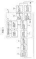
- Fig. 1 shows a circuit block diagram of a self-excited circuit of embodiment 1 of the present invention, and is structured by the ultrasonic motor 1, an amplifier 12, a phase setting circuit 13, a booster circuit 14, and a selection circuit 15. Further, a specific circuit diagram is shown in Fig. 4.
- the amplifier circuit 12 is structured by an inverter 16 and a resistor 17, and performs inverted amplification of a signal.
- a signal from the selection circuit 15, which selects a signal generated by the vibrating member 3, is input to an input of the inverter 16.
- the output voltage of the inverter 16 determines the inverted amplifying operating point of the inverter 16 in accordance with the feedback resistor 17 connecting the output to the input of the inverter 16, an AC signal centered on VDD/2 is amplified, and is input to the phase setting circuit 13.
- the inverter 16 uses a three state structure IC, and performs starting and stopping of the self-excited oscillator circuit in accordance with a control signal.
- the phase setting circuit 13 is structured by a resistor 18, and two capacitors 19 and 20, and unneeded frequency components generated by the vibrating body 3 are cut, predetermined frequency components which drive the vibrating member 3 are extracted, and phase of the same signal is set.
- the inverter 21 also regulates the phase of the self-excited oscillator circuit, along with amplifying the signal reduced by the phase setting circuit 13, performs inverted amplification of the signal passed through the phase setting circuit 13, and outputs to the base of a transistor 22.
- the transistor 22 and a booster coil 23 structure the booster circuit 14, and perform inversion boosting of the signal amplified by the inverter 21.
- the emitter of the transistor 22 is connected to ground, and the collector is electrically connected to the booster coil 23 and the vibrating body 3, namely to the common electrode llc of the piezoelectric element 2.
- One set of the electrode groups 11a and 11b composed of a plurality of electrodes is formed on one face of the piezoelectric element 2, as shown in Fig. 3A, and the common electrode 11c is formed across the entire surface of the other face.
- the vibrating member 3 also fulfills a role as an electrode, the signal boosted by the booster circuit 14 has conduction to the common electrode llc through the vibrating member 3, and the signal is input to the selection circuit 15 from the electrode groups 11a and 11b composed of the plurality of electrodes.
- the value of the boosted voltage can be made several times the voltage of the electric power supply voltage by appropriately selecting the booster coil 23, and the piezoelectric element 2 can be excited and driven. Therefore, even if the electric power supply has a low voltage of 1.5 V, it is stable and the ultrasonic motor 1 can be driven at high output.
- the selection circuit 15 is structured by, for example, one set of buffers 24a and 24b.
- the buffers 24a and 24b have a three state structure, and whether in an active state or an inactive state is determined by an external signal.
- the first electrode group 11a and the second electrode group 11b of the piezoelectric element 2 are independently connected to the input of the buffers 24a and 24b, respectively.
- the amplified buffer output signal is fed back to the amplifier circuit 12 via the phase setting capacitor 20.
- the self-excited oscillation circuit noise having many frequency components is generated when the electric power supply is connected, and unnecessary frequency components are cut by the resonance circuit composed of the ultrasonic motor 1, the resistor 18, and the capacitors 19 and 20, and a signal with a specific frequency is selected.
- the main component of the specific frequency generated in the oscillating member 3 is fed back by the amplifier circuit 12, the phase setting circuit 13, and the booster circuit 14, the inverted and boosted drive signal is interrupted, and self-excited oscillation is performed.
- the self-excited oscillation circuit oscillates naturally in correspondence with the motion of the resonance point caused by the temperature and external loads of the piezoelectric element 2, and therefore a frequency automated tracking circuit such as that of other excitation methods becomes unnecessary, and a simplification of the driver circuit is realized.
- the present embodiment is characterised in that the booster voltage is not reduced by the selection circuit 15 in accordance with connecting the selection circuit 15 to the electrode of the face which is opposite the face of the electrode connected to the booster circuit 14, and this can be supplied to the piezoelectric element 2 with good efficiency.
- the arrangement of the amplifier circuit 12 and the phase setting circuit 13 is arbitrary, and they may be formed anywhere.
- the structure is not limited to that of embodiment 1, and may be arbitrary.
- the booster circuit 14 is structured by the transistor 22 and the booster coil 23, but the effect is the same if a transformer 25 is used as a substitute for the booster coil 23.
- FIG. 5 A circuit structure using the transformer 25 is shown in Fig. 5. The differences with Fig. 4 are that the position at which the transformer 25 is connected is the emitter side of the transistor 22, and that by using the transformer 25, there is a primary side and secondary side electrical insulator.
- the collector of the transistor 22 is connected to the electric power supply voltage, the transistor 22 is placed in a conduction state by a signal input to the base, and the electric power supply voltage is applied to the primary side of the transformer 25 by the emitter. The same signal is input to GND via the transformer 25.
- the signal input to the base of the transistor 22 is OFF, a counter electric voltage of several times the electric power supply voltage is generated in the secondary side, and the booster signal is applied to the common electrode llc of the piezoelectric element 2.
- the booster circuit 14 has a similar, or larger, boosting effect when the transformer 25 is used, and it is possible to arbitrarily boost a voltage by the number of turns of the transformer 25.
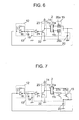
- Fig. 6, Fig. 7, and Fig. 8 may also be used as other specific circuit structures.
- Fig. 6 is an embodiment using transmission gates in the selection circuit 15.
- the transmission gates 26a and 26b By inputting the control signal to control terminals of transmission gates 26a and 26b, the transmission gates 26a and 26b can be placed into an active state or an inactive state, and the direction of motion of the moving member 4 can be controlled.
- the transmission gate 26 in an active state does not amplify a signal, like an inverter or a buffer, and the voltage excited by the vibrating member 3 is applied to the capacitor 20.
- Fig. 7 shows an embodiment in which the selection circuit 15 is structured by transistors.
- the control signal for selecting the direction of rotation to the base of transistors 27a and 27b, the rotation direction of the ultrasonic motor 1 can be selected.
- the transistors By applying the transistors, the voltage excited by the vibrating member 3 is sent through, similar to the transmission gates 26a and 26b. Further, the element voltage resistance for the transistor is extremely high compared to an IC such as an inverter or a buffer, and therefore it becomes possible to set the signal boosted by the booster circuit 14 to be high.
- Fig. 8 is an embodiment in which the selection circuit 15 is structured by inverters 28a and 28b. With a future inverter, the phase is inverted by the selection circuit 15, and therefore it becomes possible to eliminate the inverter 21 used for phase regulation, heretofore necessary. In addition to reducing the number of parts, the entire amplifier circuit can be structured by inverters, and this also contributes to reducing the types of parts. A reduction in the driver circuit can be realized by using this type of circuit structure.
- the signal boosted by the booster circuit 14 is input to the common electrode formed on one face of the piezoelectric element, is output from a plurality of electrode groups of the other side of the piezoelectric element 2 to the selection circuit 15 for selecting the switching of the signal, and by selecting this, it is possible to perform forward and reverse operation of the self-excited oscillation circuit using the booster circuit 14.
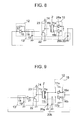
- Fig. 9 shows a specific circuit structure of embodiment 2 of the present invention, and only the points of difference with the circuit structure of embodiment 1 are explained.
- the selection circuit 15 for performing switching of the rotation direction signal has been connected directly to the plurality of electrode groups 11a and 11bof the piezoelectric element 2, but in embodiment 2, capacitors 20a and 20b which structure a phase setting circuit are inserted between these. Further, the selection circuit 15 is structured by the amplifier circuit 12 from the one group of the inverter 16 and the resistor 17. The feedback resistor 17 may also be formed in the inverter 21, not the inverter 16.
- the capacitors 20a and 20b with the piezoelectric element 2 structuring a filter circuit are inserted, but a coil may also be well used provided that it structures a filter for suppressing high frequency components. In the case of a coil, it is connected in series with the amplifier circuit 12.
- this effect can be increased by forming the resistor 18 between the inverter 16 and the capacitor 20.
- Fig. 10 is a example of a different form of the self-excited oscillation circuit shown in Fig. 9.
- Transistors 32a and 32b are formed between the capacitors 20a and 20b, and GND.
- the capacitors 20a and 20b function as filters connected to ground. Therefore, the capacitors on the side structuring the self-excited oscillator circuit can be grounded, and consequently the capacitors do not have a harmful influence with respect to the signal output by the piezoelectric effect from the electrode, from among the electrodes 11a and 11b, not used in driving. Namely, there is no harmful influence on the vibrations of the piezoelectric element 2.
- a method in which the other terminal of one of the capacitors connected to ground may be selectively connected to any of the electrodes 11a and 11b through switching means, such as a relay, may also be used.
- resistors 33a and 33b are formed in the input stage of the inverters 16a and 16b. Similar to that stated above, a signal output from the electrode from among the electrodes 11a and 11b which is not used in driving can be prevented from influencing the inverter in the inactive state.
- the inverter in the inactive state can normally be regarded as being in a high impedance state, but when the voltage level of the signal output from the electrode not used in driving is high, this state collapses, and therefore this invites harmful influence to the oscillation signal along with harmful influence to the vibration of the piezoelectric element 2, there is the possibility of reducing the stability of the oscillations and the characteristics of the motor.
- Fig. 11 shows a state of applying a control signal to control terminals of the inverters 16a and 16b, and to the bases of the transistors 32a and 32b.
- a High level signal is input to the inverter 16a and the transistor 32a, and which of the electrodes 11a and 11b structures the self-excited oscillator circuit, namely which direction the moving member is rotating, is determined.
- oscillation is started.
- High / Low level signal to the control terminal of the inverter 21, for example, it becomes possible to have stepping motion.
- the inverters 16a and 16b, and the transistors 32a and 32b here which are capable of selecting whether the self-exciting oscillator circuit is in a driving state or a non-driving state, into the driving state, the amount of time until oscillation at a predetermined resonance mode begins is quickened, and stable oscillation becomes possible. For example, if the inverters 21 and 16a, and the transistors 32a are placed in the driving state at the same time, a large noise is generated, and a long amount of time is necessary until the oscillation begins at the frequency of the predetermined resonance mode, and depending upon the circumstances, abnormal oscillations are caused, and there are cases when driving cannot be done.
- the inverter 16a set into the driving state, by setting the inverter 21 into the driving state after the electric potential of the input stage of the inverter 16a reaches the operation point VDD/2, the amount of time until the oscillations begin can be quickened.
- control signal application is not limited to the self-excited oscillation circuit shown in embodiment 2, and of course a similar effect can also be obtained when applied to a self-excited oscillation circuit not having a booster circuit.
- Fig. 12 shows a specific circuit structure of embodiment 3 of the present invention, and only points, which differ with the circuit structures of the above embodiments, are explained.
- a signal inverted and boosted by the booster circuit is input to the common electrode llc formed on one face of the piezoelectric element 2, and the signal excited by the vibrating body is output from a detecting electrode portion lid for detecting a drive signal and which is formed in the other face of the piezoelectric element 2.
- the signal output from the detecting electrode portion lid is fed back to the amplifier circuit 12.
- Transistors 29a and 29b are used in the selection circuit 15 for selecting the rotation direction of the ultrasonic motor 1, and by inputting a control signal for selecting the direction of rotation into the base of the transistors 29a and 29b, the signal generated by the vibrating member flows in each transistor, and the same signal flows into GND.
- the signal output from the detecting electrode portion is always fed back to the amplifier circuit, regardless of rotation direction, and self-excitation is performed.
- the detecting electrode portion 11d is shown in Fig. 13.
- the detecting electrode portion 11d is formed on the same side as the first electrode group 11a and the second electrode group 11b.
- a driving signal having the main frequency components, and with few unnecessary frequency components can be detected.
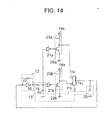
- Fig. 14 shows a specific circuit diagram of embodiment 4 of the present invention.
- a structure is used in which output from two booster circuits composed of transistors 22a and 22b, and coils 23a and 23b, can be supplied to the electrodes 11a and 11b.
- output signal it is possible to select which booster circuit is set into the active state, and which is set into the inactive state, in accordance with output signal switching means composed of three state inverters 21a and 21b.
- output signal switching means composed of three state inverters 21a and 21b.
- the signal is output from the inverter, from among the inverters 21a and 21b, which becomes active, then the signal from the booster circuit connected to the inverter is output to the electrode.
- the insulating strength of the transistor is high in comparison with parts such as inverters, and therefore it is difficult to be influenced by the signal output fromthe electrode not used in driving, and the ultrasonic motor can be driven at high power.
- a structure having the output signal switching means capable of selecting which of the plurality of booster circuits may be made capable of outputting is used here, but a structure having output signal switching means capable of selecting which electrode one booster circuit to supply this output may also be used.
- a method may be used for selecting the output electrode of the booster signal by which a part such as a relay becomes an output signal switching means, and two relays are formed between each two electrodes and one booster circuit. In this case the insulating strength of the relays is extremely high, and therefore there is hardly any influence from the signal output from the electrode not used in driving, and the ultrasonic motor can be driven at high power.
- Fig. 15 shows a block diagram of the ultrasonic motor 1 of the present invention being applied as a drive source to an electronic device, and is an electronic device having an ultrasonic motor structured by the piezoelectric element 2, the vibrating member 3, the pressurization means 6, the moving member 4, a transmission mechanism 30, and an output mechanism 31.
- Embodiment 5 is structured from the piezoelectric element 2, the vibrating member 3 contacting the piezoelectric element 2, the moving member 4 which periodically applies pressure to the vibrating member 3, the output mechanism 31 capable of moving based on the operation of the transmission means 30 which operates in unity with the moving member 3, and the pressurization mechanism 6 which applies pressure to the moving member 4.
- the output mechanism 31 uses a paper feeding mechanism in a printer; a shutter drive mechanism, a lens drive mechanism, or a filmwinding mechanism or the like in a camera; the hands in an electronic clock or measurement device; an armmechanism in a robot; or a gear advancing mechanism or a processing member advancing mechanism in a machine tool.
- an electronic clock a measuring device, a camera, a printer, a printing machine, a robot, a machine tool, a game machine, and a moving device or the like can be realized.
- an ultrasonic motor driven device can be realized.
- the present invention is structured by an ultrasonic motor composed of a vibrating member having a piezoelectric element and an oscillator circuit for self-excited oscillation of the vibrating member at a predetermined resonance mode, and which drives a moving member by an oscillatory wave generated in the vibrating member, a booster circuit for boosting an electric voltage generated by an amplifier circuit, and outputting a signal to a common electrode formed on one face of the piezoelectric element, and a selection circuit for switching a signal path of a booster signal output from a plurality of electrode groups formed on another face of the piezoelectric element.
- the signal generated by the booster circuit is output to the common electrode formed on one face of the piezoelectric element, and the booster signal input to the common electrode is output from the plurality of electrode groups formed on the other face to the selection circuit for switching the signal path, and it thus becomes possible to control forward and reverse rotation directions by one set of booster circuits.
- An increase in the number of parts is therefore suppressed, and a self-excited drive circuit capable of forward and reverse operation can be realized usingaboostercircuit, and an electronic device having an ultrasonic motor can be provided.
Landscapes
- General Electrical Machinery Utilizing Piezoelectricity, Electrostriction Or Magnetostriction (AREA)
Abstract
Description
Claims (13)
- An ultrasonic motor comprising:a piezoelectric element having a plurality of electrode groups formed on one surface; a common electrode formed on another surface; a plurality of drive portions capable of independent drive in accordance with a drive signal applied between said at least one electrode from among said plurality of electrode groups and said common electrode;a vibrating member having said piezoelectric element;an oscillator circuit self-excited by a predetermined resonance mode of said vibrating member;an amplifier circuit to amplify a signal of said oscillator circuit;a booster circuit to boost a voltage signal obtained from said amplifier circuit and to output the signal to said common electrode; anda selection circuit to switch a signal path of a signal output from said plurality of electrode groups.
- The ultrasonic motor as claimed in claim 1, wherein said booster circuit is composed of at least one set of a coil and a transistor.
- The ultrasonic motor as claimed in claim 1, wherein said booster circuit is composed of at least one set of a transformer and a transistor.
- The ultrasonic motor as claimed in claim 1, wherein said selection circuit has at least one set of an amplifier circuit.
- The ultrasonic motor as claimed in claim 1, wherein a filter circuit is arranged between said plurality of electrode groups of said piezoelectric element and said selection circuit to switch the signal path output from said plurality of electrode groups.
- The ultrasonic motor as claimed in claim 5, wherein said filter circuit is capable of selecting whether or not to function as a filter circuit in response to an external command signal.
- The ultrasonic motor as claimed in claim 1, wherein: said one face of said piezoelectric element has, in addition to said plurality of electrode groups formed in said plurality of drive portions, respectively, a detection electrode portion for detecting a drive signal based on a vibration of said vibrating member; and by feeding back a detection signal obtained from said detection electrode portion, structuring a self-exciting oscillator circuit.
- The ultrasonic motor as claimed in claim 7, wherein said selection circuit selects whether or not to short said plurality of electrode groups and GND.
- An ultrasonic motor comprising:a piezoelectric element having a plurality of electrode groups formed on one surface; a common electrode formed on another surface; a plurality of drive portions capable of independent drive in accordance with a drive signal applied between at least one electrode from among said plurality of electrode groups and said common electrode;a vibrating member having said piezoelectric element;an oscillator circuit self-excited by a predetermined resonance mode of said vibrating member;an amplifier circuit to amplify a signal of said oscillator circuit;a booster circuit to boost a voltage signal obtained from said amplifier circuit and to output the signal to said common electrode; anda switch for an output signal to select whether or not to output an output signal from said booster circuit to any of said plurality of electrodes.
- An ultrasonic motor comprising:wherein said oscillator circuit moves from said non-driving state to said driving state by setting at least one switching circuit of said plurality of switching circuits into said driving state, and to set the remaining switching circuits into said non-driving state.a vibrating member having a piezoelectric element;an oscillator circuit which is self-excited by a predetermined resonance mode of said vibrating member, and has a plurality of switching circuits to select a driving state and a non-driving state; andan amplifier circuit to amplify a signal of said oscillator circuit;
- An electronic device with an ultrasonic motor, having the ultrasonic motor as claimed in claim 1, wherein:
said ultrasonic motor has a transfer mechanism which operates in uniformity with a moving member, and an output mechanism which operates based on operation of said transfer mechanism. - An electronic device with an ultrasonic motor, having the ultrasonic motor as claimed in claim 9, wherein:
said ultrasonic motor has a transfer mechanism which operates in uniformity with a moving member, and an output mechanism which operates based on operation of said transfer mechanism. - An electronic device with an ultrasonic motor, having the ultrasonic motor as claimed in claim 10, wherein:
said ultrasonic motor has a transfer mechanism which operates in uniformity with a moving member, and an output mechanism which operates based on operation of said transfer mechanism.
Applications Claiming Priority (4)
| Application Number | Priority Date | Filing Date | Title |
|---|---|---|---|
| JP33606199 | 1999-11-26 | ||
| JP33606199 | 1999-11-26 | ||
| JP2000319792A JP4694681B2 (en) | 1999-11-26 | 2000-10-19 | Ultrasonic motor and electronic device with ultrasonic motor |
| JP2000319792 | 2000-10-19 |
Publications (2)
| Publication Number | Publication Date |
|---|---|
| EP1104085A2 true EP1104085A2 (en) | 2001-05-30 |
| EP1104085A3 EP1104085A3 (en) | 2003-01-29 |
Family
ID=26575344
Family Applications (1)
| Application Number | Title | Priority Date | Filing Date |
|---|---|---|---|
| EP00310320A Withdrawn EP1104085A3 (en) | 1999-11-26 | 2000-11-21 | Driving circuit for ultrasonic rotary motor |
Country Status (3)
| Country | Link |
|---|---|
| US (1) | US6573636B1 (en) |
| EP (1) | EP1104085A3 (en) |
| JP (1) | JP4694681B2 (en) |
Cited By (3)
| Publication number | Priority date | Publication date | Assignee | Title |
|---|---|---|---|---|
| US6573636B1 (en) * | 1999-11-26 | 2003-06-03 | Seiko Instruments Inc. | Ultrasonic motor having single booster circuit and electronic device with ultrasonic motor |
| CN104601035A (en) * | 2013-10-30 | 2015-05-06 | 精工爱普生株式会社 | PIEZOELECTRIC MOTOR, ROBOT HAND, ROBOT, and FINGER ASSIST APPARATUS |
| CN106505909A (en) * | 2016-11-17 | 2017-03-15 | 闽江学院 | Nonlinear Dead Zone Compensation Control System and Method for Ultrasonic Motor Based on Generalized Regression Neural Network |
Families Citing this family (11)
| Publication number | Priority date | Publication date | Assignee | Title |
|---|---|---|---|---|
| US20050127782A1 (en) * | 2001-12-21 | 2005-06-16 | Morinobu Endo | Ultrasonic motor, and electronic timepiece having ultrasonic motor |
| JP2004297951A (en) * | 2003-03-27 | 2004-10-21 | Olympus Corp | Ultrasonic vibrator and ultrasonic motor |
| JP4141990B2 (en) * | 2004-07-12 | 2008-08-27 | セイコーエプソン株式会社 | Piezoelectric actuators and equipment |
| US7856272B2 (en) * | 2006-04-28 | 2010-12-21 | Flint Hills Scientific, L.L.C. | Implantable interface for a medical device system |
| FR2907616B1 (en) | 2006-10-19 | 2009-01-16 | Sagem Defense Securite | TWO AXIS ORIENTATION TURRET WITH ELECTRIC PIEZO MOTORIZATION |
| JP4847401B2 (en) * | 2007-06-18 | 2011-12-28 | 本田技研工業株式会社 | Mobile robot drive unit |
| DE112007003552T5 (en) * | 2007-06-20 | 2010-06-10 | Advantest Corporation | Fault meter and tester |
| TWI397252B (en) * | 2009-10-26 | 2013-05-21 | Metal Ind Res & Dev Ct | Single-stage zero-current switching driving circuit for ultrasonic motor |
| CN102064731B (en) * | 2009-11-18 | 2013-07-24 | 财团法人金属工业研究发展中心 | Unipolar Zero Current Switching Drive Circuit for Ultrasonic Motors |
| CN103560739A (en) * | 2013-08-24 | 2014-02-05 | 渭南高新区金石为开咨询有限公司 | Driving module with zero-crossing current switching applied in vibration motor |
| US10030976B2 (en) * | 2015-05-13 | 2018-07-24 | Kionix, Inc. | Phase-based measurement and control of a gyroscope |
Family Cites Families (33)
| Publication number | Priority date | Publication date | Assignee | Title |
|---|---|---|---|---|
| JPS57211087A (en) * | 1981-06-22 | 1982-12-24 | Seiko Instr & Electronics Ltd | Boosting circuit of electronic timepiece element |
| JP2934964B2 (en) * | 1988-01-09 | 1999-08-16 | セイコーインスツルメンツ株式会社 | Ultrasonic motor and method of manufacturing ultrasonic motor |
| JPH02119586A (en) * | 1988-10-27 | 1990-05-07 | Seiko Instr Inc | Ultrasonic motor unit |
| JP2815219B2 (en) * | 1990-04-20 | 1998-10-27 | アスモ株式会社 | Ultrasonic motor drive circuit and multiple motor drive signal supply circuit |
| JPH05273361A (en) * | 1992-03-24 | 1993-10-22 | Seiko Instr Inc | Electronic device with ultrasonic motor |
| JP3207549B2 (en) * | 1992-09-11 | 2001-09-10 | セイコーインスツルメンツ株式会社 | Ultrasonic motor |
| KR100204460B1 (en) * | 1992-12-16 | 1999-06-15 | 모리시타 요이찌 | Speed Control Method of Ultrasonic Motor |
| JPH07170772A (en) * | 1993-10-21 | 1995-07-04 | Seiko Instr Inc | Ultrasonic motor and electronic equipment with ultrasonic motor |
| JP2973273B2 (en) * | 1994-05-13 | 1999-11-08 | セイコーエプソン株式会社 | Electronic clock and charging method thereof |
| JPH08116685A (en) * | 1994-10-17 | 1996-05-07 | Canon Inc | Vibration wave motor |
| US5619089A (en) * | 1994-10-31 | 1997-04-08 | Seiko Instruments Inc. | Ultrasonic motor and electronic apparatus provided with an ultrasonic motor |
| JP2718392B2 (en) * | 1995-03-28 | 1998-02-25 | 日本電気株式会社 | Drive circuit for piezoelectric transformer |
| US5777232A (en) * | 1995-03-29 | 1998-07-07 | Shinko Electric Co., Ltd. | Control system for vibratory apparatus |
| EP0758159B1 (en) * | 1995-08-07 | 2002-04-10 | Nec Corporation | Converter wherein a piezoelectric transformer input signal is frequency modulated by a pulse width modulated signal |
| JP2952815B2 (en) | 1995-10-02 | 1999-09-27 | セイコーインスツルメンツ株式会社 | Ultrasonic motor device |
| JP2778554B2 (en) * | 1995-10-12 | 1998-07-23 | 日本電気株式会社 | Piezo transformer drive circuit |
| JP4080590B2 (en) * | 1997-05-08 | 2008-04-23 | セイコーインスツル株式会社 | Ultrasonic motor device and electronic apparatus with ultrasonic motor device |
| JP3641902B2 (en) * | 1997-05-27 | 2005-04-27 | 株式会社ニコン | Drive device |
| JPH11178369A (en) * | 1997-12-09 | 1999-07-02 | Seiko Instruments Inc | Ultrasonic motor and electronic equipment with ultrasonic motor |
| WO1999019979A1 (en) * | 1997-10-14 | 1999-04-22 | Seiko Instruments Inc. | Power generating block provided with thermoelectric generation unit |
| JPH11218587A (en) * | 1997-11-25 | 1999-08-10 | Seiko Instruments Inc | Electronic watch with thermoelectric element |
| JP3657445B2 (en) * | 1998-01-28 | 2005-06-08 | セイコーインスツル株式会社 | Electronics |
| JP3051921B2 (en) * | 1998-02-05 | 2000-06-12 | セイコーインスツルメンツ株式会社 | Ultrasonic motor and electronic equipment with ultrasonic motor |
| JP3173585B2 (en) * | 1998-02-27 | 2001-06-04 | 日本電気株式会社 | Driving method and driving circuit for piezoelectric transformer |
| JP3069074B2 (en) * | 1998-02-27 | 2000-07-24 | スター精密株式会社 | Driving method of ultrasonic motor |
| JP3650276B2 (en) * | 1998-10-22 | 2005-05-18 | セイコーインスツル株式会社 | Electronic portable equipment |
| JP3061043B2 (en) * | 1998-12-11 | 2000-07-10 | 日本電気株式会社 | Power supply circuit |
| JP3171187B2 (en) * | 1999-03-30 | 2001-05-28 | ミノルタ株式会社 | Piezo actuator |
| JP4694681B2 (en) * | 1999-11-26 | 2011-06-08 | セイコーインスツル株式会社 | Ultrasonic motor and electronic device with ultrasonic motor |
| JP2001258278A (en) * | 2000-03-15 | 2001-09-21 | Minolta Co Ltd | Drive control device for truss type actuator |
| US6429987B1 (en) * | 2000-04-10 | 2002-08-06 | Marvell International, Inc. | High speed inductor current driver with minimum overshoot |
| JP2001356017A (en) * | 2000-06-14 | 2001-12-26 | Alps Electric Co Ltd | Vibrator drive detection device |
| US6476542B2 (en) * | 2000-12-20 | 2002-11-05 | Cts Corporation | Piezoelectric transformer with dual-phase input drive |
-
2000
- 2000-10-19 JP JP2000319792A patent/JP4694681B2/en not_active Expired - Fee Related
- 2000-11-16 US US09/714,697 patent/US6573636B1/en not_active Expired - Lifetime
- 2000-11-21 EP EP00310320A patent/EP1104085A3/en not_active Withdrawn
Cited By (5)
| Publication number | Priority date | Publication date | Assignee | Title |
|---|---|---|---|---|
| US6573636B1 (en) * | 1999-11-26 | 2003-06-03 | Seiko Instruments Inc. | Ultrasonic motor having single booster circuit and electronic device with ultrasonic motor |
| CN104601035A (en) * | 2013-10-30 | 2015-05-06 | 精工爱普生株式会社 | PIEZOELECTRIC MOTOR, ROBOT HAND, ROBOT, and FINGER ASSIST APPARATUS |
| CN104601035B (en) * | 2013-10-30 | 2018-04-06 | 精工爱普生株式会社 | Piezo-electric motor, robot, robot, finger servicing unit |
| CN106505909A (en) * | 2016-11-17 | 2017-03-15 | 闽江学院 | Nonlinear Dead Zone Compensation Control System and Method for Ultrasonic Motor Based on Generalized Regression Neural Network |
| CN106505909B (en) * | 2016-11-17 | 2018-09-18 | 闽江学院 | A kind of supersonic motor nonlinear dead-zone compensation control system and method |
Also Published As
| Publication number | Publication date |
|---|---|
| JP4694681B2 (en) | 2011-06-08 |
| EP1104085A3 (en) | 2003-01-29 |
| JP2001218484A (en) | 2001-08-10 |
| US6573636B1 (en) | 2003-06-03 |
Similar Documents
| Publication | Publication Date | Title |
|---|---|---|
| US6573636B1 (en) | Ultrasonic motor having single booster circuit and electronic device with ultrasonic motor | |
| US4743788A (en) | Input frequency control device for surface acoustic wave motor | |
| EP0602635B1 (en) | A method and an apparatus for controlling a moving velocity of an ultrasonic motor | |
| US5920144A (en) | Vibrating actuator device | |
| US5592041A (en) | Ultrasonic motor and electronic apparatus equipped with ultrasonic motor | |
| EP0767504B1 (en) | Ultrasonic motor device | |
| US5744897A (en) | Driving control device for vibration wave motor | |
| JPH06237584A (en) | Speed control method and speed controller for ultrasonic motor | |
| JP2737420B2 (en) | Ultrasonic motor drive system | |
| US5777444A (en) | Drive device for a vibration actuator which prevents the cogging phenomenon | |
| US6388362B1 (en) | Ultrasonic motor and electronic apparatus having ultrasonic motor | |
| US20020003384A1 (en) | Ultrasonic motor and electronic apparatus having an ultrasonic motor | |
| JP2001178156A (en) | Ultrasonic motor and electronic device with ultrasonic motor | |
| JPH06315283A (en) | Drive circuit for ultrasonic motor | |
| JP4529237B2 (en) | Vibration actuator | |
| JP3495810B2 (en) | Vibration wave motor device | |
| JPH04313369A (en) | Ultrasonic actuator driving circuit | |
| JPH0715984A (en) | Ultrasonic actuator | |
| JP3308711B2 (en) | Ultrasonic motor drive | |
| JP2893919B2 (en) | Drive control device for vibrator | |
| JP4732623B2 (en) | Ultrasonic motor and electronic device equipped with ultrasonic motor | |
| JP2003284365A (en) | Ultrasonic motor device and electronic device with ultrasonic motor | |
| JPH10155289A (en) | Vibration device and vibration control device | |
| JPH04185288A (en) | Driving circuit of ultrasonic motor | |
| JPH0488889A (en) | Driver for ultrasonic motor |
Legal Events
| Date | Code | Title | Description |
|---|---|---|---|
| PUAI | Public reference made under article 153(3) epc to a published international application that has entered the european phase |
Free format text: ORIGINAL CODE: 0009012 |
|
| AK | Designated contracting states |
Kind code of ref document: A2 Designated state(s): AT BE CH CY DE DK ES FI FR GB GR IE IT LI LU MC NL PT SE TR |
|
| AX | Request for extension of the european patent |
Free format text: AL;LT;LV;MK;RO;SI |
|
| PUAL | Search report despatched |
Free format text: ORIGINAL CODE: 0009013 |
|
| AK | Designated contracting states |
Designated state(s): AT BE CH CY DE DK ES FI FR GB GR IE IT LI LU MC NL PT SE TR |
|
| AX | Request for extension of the european patent |
Extension state: AL LT LV MK RO SI |
|
| 17P | Request for examination filed |
Effective date: 20030715 |
|
| AKX | Designation fees paid |
Designated state(s): DE FR GB |
|
| 17Q | First examination report despatched |
Effective date: 20050330 |
|
| STAA | Information on the status of an ep patent application or granted ep patent |
Free format text: STATUS: THE APPLICATION IS DEEMED TO BE WITHDRAWN |
|
| 18D | Application deemed to be withdrawn |
Effective date: 20050810 |