EP1104040A1 - Nonaqueous electrolyte secondary battery - Google Patents
Nonaqueous electrolyte secondary battery Download PDFInfo
- Publication number
- EP1104040A1 EP1104040A1 EP00125817A EP00125817A EP1104040A1 EP 1104040 A1 EP1104040 A1 EP 1104040A1 EP 00125817 A EP00125817 A EP 00125817A EP 00125817 A EP00125817 A EP 00125817A EP 1104040 A1 EP1104040 A1 EP 1104040A1
- Authority
- EP
- European Patent Office
- Prior art keywords
- battery
- battery element
- positive electrode
- negative electrode
- nonaqueous electrolyte
- Prior art date
- Legal status (The legal status is an assumption and is not a legal conclusion. Google has not performed a legal analysis and makes no representation as to the accuracy of the status listed.)
- Withdrawn
Links
- 239000011255 nonaqueous electrolyte Substances 0.000 title claims abstract description 18
- 238000004804 winding Methods 0.000 claims abstract description 8
- 238000010030 laminating Methods 0.000 claims abstract description 3
- HBBGRARXTFLTSG-UHFFFAOYSA-N Lithium ion Chemical group [Li+] HBBGRARXTFLTSG-UHFFFAOYSA-N 0.000 claims description 7
- 229910001416 lithium ion Inorganic materials 0.000 claims description 7
- 238000000926 separation method Methods 0.000 description 8
- 239000000463 material Substances 0.000 description 4
- 235000017166 Bambusa arundinacea Nutrition 0.000 description 2
- 235000017491 Bambusa tulda Nutrition 0.000 description 2
- 241001330002 Bambuseae Species 0.000 description 2
- XEEYBQQBJWHFJM-UHFFFAOYSA-N Iron Chemical compound [Fe] XEEYBQQBJWHFJM-UHFFFAOYSA-N 0.000 description 2
- 235000015334 Phyllostachys viridis Nutrition 0.000 description 2
- 229910052782 aluminium Inorganic materials 0.000 description 2
- XAGFODPZIPBFFR-UHFFFAOYSA-N aluminium Chemical compound [Al] XAGFODPZIPBFFR-UHFFFAOYSA-N 0.000 description 2
- 239000011425 bamboo Substances 0.000 description 2
- 238000006243 chemical reaction Methods 0.000 description 2
- 230000000694 effects Effects 0.000 description 2
- RYGMFSIKBFXOCR-UHFFFAOYSA-N Copper Chemical compound [Cu] RYGMFSIKBFXOCR-UHFFFAOYSA-N 0.000 description 1
- WHXSMMKQMYFTQS-UHFFFAOYSA-N Lithium Chemical compound [Li] WHXSMMKQMYFTQS-UHFFFAOYSA-N 0.000 description 1
- 239000004642 Polyimide Substances 0.000 description 1
- 229910000831 Steel Inorganic materials 0.000 description 1
- 239000002390 adhesive tape Substances 0.000 description 1
- 239000011248 coating agent Substances 0.000 description 1
- 238000000576 coating method Methods 0.000 description 1
- 239000011889 copper foil Substances 0.000 description 1
- 230000008021 deposition Effects 0.000 description 1
- 230000008030 elimination Effects 0.000 description 1
- 238000003379 elimination reaction Methods 0.000 description 1
- 238000003780 insertion Methods 0.000 description 1
- 230000037431 insertion Effects 0.000 description 1
- 229910052742 iron Inorganic materials 0.000 description 1
- 229910052744 lithium Inorganic materials 0.000 description 1
- 229910052751 metal Inorganic materials 0.000 description 1
- 239000002184 metal Substances 0.000 description 1
- 239000007769 metal material Substances 0.000 description 1
- 229920001721 polyimide Polymers 0.000 description 1
- 229910001220 stainless steel Inorganic materials 0.000 description 1
- 239000010935 stainless steel Substances 0.000 description 1
- 239000010959 steel Substances 0.000 description 1
Images

Classifications
-
- H—ELECTRICITY
- H01—ELECTRIC ELEMENTS
- H01M—PROCESSES OR MEANS, e.g. BATTERIES, FOR THE DIRECT CONVERSION OF CHEMICAL ENERGY INTO ELECTRICAL ENERGY
- H01M10/00—Secondary cells; Manufacture thereof
- H01M10/05—Accumulators with non-aqueous electrolyte
- H01M10/058—Construction or manufacture
- H01M10/0587—Construction or manufacture of accumulators having only wound construction elements, i.e. wound positive electrodes, wound negative electrodes and wound separators
-
- H—ELECTRICITY
- H01—ELECTRIC ELEMENTS
- H01M—PROCESSES OR MEANS, e.g. BATTERIES, FOR THE DIRECT CONVERSION OF CHEMICAL ENERGY INTO ELECTRICAL ENERGY
- H01M10/00—Secondary cells; Manufacture thereof
- H01M10/04—Construction or manufacture in general
- H01M10/0431—Cells with wound or folded electrodes
-
- H—ELECTRICITY
- H01—ELECTRIC ELEMENTS
- H01M—PROCESSES OR MEANS, e.g. BATTERIES, FOR THE DIRECT CONVERSION OF CHEMICAL ENERGY INTO ELECTRICAL ENERGY
- H01M10/00—Secondary cells; Manufacture thereof
- H01M10/05—Accumulators with non-aqueous electrolyte
- H01M10/052—Li-accumulators
- H01M10/0525—Rocking-chair batteries, i.e. batteries with lithium insertion or intercalation in both electrodes; Lithium-ion batteries
-
- H—ELECTRICITY
- H01—ELECTRIC ELEMENTS
- H01M—PROCESSES OR MEANS, e.g. BATTERIES, FOR THE DIRECT CONVERSION OF CHEMICAL ENERGY INTO ELECTRICAL ENERGY
- H01M6/00—Primary cells; Manufacture thereof
- H01M6/04—Cells with aqueous electrolyte
- H01M6/06—Dry cells, i.e. cells wherein the electrolyte is rendered non-fluid
- H01M6/10—Dry cells, i.e. cells wherein the electrolyte is rendered non-fluid with wound or folded electrodes
- H01M2006/106—Elliptic wound cells
-
- H—ELECTRICITY
- H01—ELECTRIC ELEMENTS
- H01M—PROCESSES OR MEANS, e.g. BATTERIES, FOR THE DIRECT CONVERSION OF CHEMICAL ENERGY INTO ELECTRICAL ENERGY
- H01M50/00—Constructional details or processes of manufacture of the non-active parts of electrochemical cells other than fuel cells, e.g. hybrid cells
- H01M50/10—Primary casings; Jackets or wrappings
- H01M50/102—Primary casings; Jackets or wrappings characterised by their shape or physical structure
- H01M50/103—Primary casings; Jackets or wrappings characterised by their shape or physical structure prismatic or rectangular
-
- Y—GENERAL TAGGING OF NEW TECHNOLOGICAL DEVELOPMENTS; GENERAL TAGGING OF CROSS-SECTIONAL TECHNOLOGIES SPANNING OVER SEVERAL SECTIONS OF THE IPC; TECHNICAL SUBJECTS COVERED BY FORMER USPC CROSS-REFERENCE ART COLLECTIONS [XRACs] AND DIGESTS
- Y02—TECHNOLOGIES OR APPLICATIONS FOR MITIGATION OR ADAPTATION AGAINST CLIMATE CHANGE
- Y02E—REDUCTION OF GREENHOUSE GAS [GHG] EMISSIONS, RELATED TO ENERGY GENERATION, TRANSMISSION OR DISTRIBUTION
- Y02E60/00—Enabling technologies; Technologies with a potential or indirect contribution to GHG emissions mitigation
- Y02E60/10—Energy storage using batteries
-
- Y—GENERAL TAGGING OF NEW TECHNOLOGICAL DEVELOPMENTS; GENERAL TAGGING OF CROSS-SECTIONAL TECHNOLOGIES SPANNING OVER SEVERAL SECTIONS OF THE IPC; TECHNICAL SUBJECTS COVERED BY FORMER USPC CROSS-REFERENCE ART COLLECTIONS [XRACs] AND DIGESTS
- Y02—TECHNOLOGIES OR APPLICATIONS FOR MITIGATION OR ADAPTATION AGAINST CLIMATE CHANGE
- Y02P—CLIMATE CHANGE MITIGATION TECHNOLOGIES IN THE PRODUCTION OR PROCESSING OF GOODS
- Y02P70/00—Climate change mitigation technologies in the production process for final industrial or consumer products
- Y02P70/50—Manufacturing or production processes characterised by the final manufactured product
Definitions
- the present invention relates to a nonaqueous electrolyte secondary battery, and in particular, to a nonaqueous electrolyte secondary battery using a rectangular type battery case.
- Nonaqueous electrolyte secondary battery is used as power source for small-size electronic devices.
- nonaqueous electrolyte batteries cylindrical type batteries or rectangular type batteries are used.
- a positive electrode and a negative electrode are produced by coating active components on a positive electrode current collector and a negative electrode current collector respectively. These electrodes are laminated on each other with a separator interposed between them, and these are wound up, and a battery element is prepared. This battery element is accommodated in a battery case and is sealed, and this is used as a sealed battery.
- a cylindrical type battery is produced by accommodating a battery element wound up in cylindrical shape into a cylindrical battery case.
- the rectangular type battery is produced by accommodating the battery element into a battery case in the shape other than cylindrical shape, e.g. in form of rectangular parallelepiped.
- the battery element In the cylindrical type battery, the battery element is designed in cylindrical shape. When it is accommodated in the battery case, the force is evenly applied on the battery element, and battery reaction also occurs evenly without being deviated to a specific point.
- the devices such as notebook-size personal computer, cellphone, etc. where the batteries are used, are usually designed in form of rectangular parallelepiped.
- this type of battery accommodating compartment there is a problem in that ineffective or useless volume is increased in the cylindrical battery because the diameter of the cylindrical type battery is limited by the thickness of the battery accommodating compartment.
- Problem may arise in that it is not possible to use a cylindrical type battery of large capacity for a thin-walled type devices.
- a rectangular type battery with smaller thickness is used instead of a cylindrical type battery.
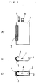
- Fig. 3 shows a conventional type nonaqueous electrolyte secondary battery.
- Fig. 3 (A) is a side view of a battery element for a rectangular type battery
- Fig. 3 (B) is a plan view of a battery element for a rectangular type battery
- Fig. 3 (C) is a plan view of a rectangular type battery case with the battery element accommodated in it as seen from above.
- a nickel-plated layer is formed, and this is used as a battery case of a nonaqueous electrolyte secondary battery 1.
- a battery element 3 is accommodated, which is produced by winding up a positive electrode with a positive electrode active component coated on it and a negative electrode with negative electrode active component coated on it with a separator interposed between them.
- a positive electrode tab 4 is mounted on the positive electrode, and a negative electrode tab 5 is mounted on the negative electrode.
- belt-like members are laminated on each other in the order of positive electrode - separator - negative electrode - separator.
- the negative electrode is wound up on outer side, and a separation-preventive tape 7 is used to fix the separator surface on the outermost periphery and to prevent partial separation of the battery element. Then, the battery element is accommodated in the battery case 2.
- the separator on the outermost periphery protects the battery element. It is also used for the purpose of improving the sliding performance between the battery element and inner surface of metal material such as aluminum, stainless steel, or nickel-plated soft steel used as the battery case. Further, it is used for the purpose of facilitating the insertion of the battery element or of preventing deformation of the wound-up battery element, just as the separation of outer shell of a bamboo shoot, due to the friction with the inner surface of the battery case.
- the separator on the outermost layer is originally not required, and, when it is used, it adds additional ineffective thickness to the battery element.
- the thickness of the separator on battery capacity gives increasingly more serious influence.
- a battery element of about 3.2 mm in thickness is used.
- the separators each of 0.05 mm in thickness arranged on each side on outer periphery occupy about 3% of the total volume of the battery element.
- the rectangular type lithium ion secondary batteries are also used in small-size devices, and there are now strong demands on the reduction of battery volume and on the increase of battery capacity. Therefore, the reduction-or elimination of the portions not contributing to the battery capacity in the battery is very important to increase the battery capacity.
- the present invention provides a nonaqueous electrolyte secondary battery, comprising a battery element produced by laminating and winding up a positive electrode and a negaive electrode with a separator interposed therebetween, a separator is not provided on the outermost periphery of the battery element, a current collector surface of one of the positive electrode or the negative electrode is exposed to outside, and a separation-preventive tape is attached on the battery element except a part of one of the longer sides on the outermost periphery.
- each of current collectors of an electrode of the same polarity as that of a battery case is exposed to outside on the outermost periphery, and a separator is not used on the outermost periphery.
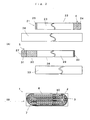
- Fig. 1 shows an example of a nonaqueous electrolyte secondary battery according to the present invention.
- Fig. 1 (A) is a side view of a rectangular type battery case with a part of a battery element accommodated in it
- Fig. 1 (B) is a plan view of a battery case of a battery with the battery element accommodated in it and with a top cover not mounted on it.
- a battery element 3 is accommodated.
- a positive electrode tab 4 and a negative electrode tab 5 for current collection are provided.
- a current collector surface 6 with electrode active component not coated on it is provided on the outermost periphery of the battery element 3.
- a separation-preventive tape 7 is attached on the current collector surface 6, except a part of one of the longer sides for preventing partial separation of the wound-up battery element and for reducing friction when the battery element is accommodated into the battery case. This makes it possible to prevent partial separation of the battery element, which occurs just like the separation of outer shell of a bamboo shoot, when the battery element is placed into the battery case. It is also possible to overcome the difficulty due to friction with the inner side of the battery case when the battery element is accommodated into the battery case and to prevent damage of the battery element caused by such friction.
- Fig. 2 shows another example of the battery of the present invention.
- Fig. 2 (A) represents development plans, each showing a positive electrode and a negative electrode each in belt-like shape, and a separator (the central portion is not shown in each case), and
- Fig. 2 (B) is a cross-sectional view of the battery.
- a positive electrode active component coated portion 23 where a positive electrode active component is coated is formed on each surface of a belt-like positive electrode current collector 22 made of a material such as aluminum.
- positive electrode active component non-coated portions 24 and 25 where positive electrode active component is not coated are provided respectively.
- the positive electrode active component non-coated portion 24 is positioned on a winding core when the positive and the negative electrodes are laminated on each other with a first separator 26 interposed between them and are wound up.
- a positive electrode tab 4 is provided, which is electrically connected to the positive electrode 21 and an external connecting terminal on the battery case.
- a negative electrode active component coated portion 29 to match the positive electrode active component coated portion 28 is arranged on a negative electrode current collector 28 made of a copper foil.
- a negative electrode current collector positioned on outer periphery a negative electrode active component one-side coated portion 30 where the negative electrode active component is coated only on one side and a negative electrode active component non-coated portion 31 where the negative electrode active component is not coated are provided.
- a negative electrode tab 5 is mounted on the negative electrode active component non-coated portion 31 on the negative electrode active component non-coated portion 31, a negative electrode tab 5 is mounted.
- a first separator 26 is arranged on an end 32 closer to the winding core of the negative electrode and is extended beyond the positive electrode active component coated portion 23.
- a second separator 33 is arranged on the negative electrode active component one-side coated portion 30 and the negative electrode active component non-coated portion 31 on the outermost periphery of the battery element in such a length that the negative electrode active component non-coated portion 31 is exposed to the outermost periphery of the battery element and it is extended beyond the positive electrode active component coated portion 23, and these are laminated on each other and are wound up.
- a separation-preventive tape 7 is attached on the current collector surface 6, which comprises the negative electrode active component one-side coated portion 30, except a part of one longer side of the battery element. Then, the battery element is accommodated in the battery case.
- the separation-preventive tape 7 can provide an effect to reduce the volume of the battery element compared with the case the separator is used on the outermost periphery when the battery element is attached on the entire surface.
- Fig. 1 or Fig. 2 (B) when the separation-preventive tape is attached except a part of one longer side of the battery element, i.e. except the central portion on the surface on the longer side, higher effect can be attained to reduce the volume of the battery element.
- the separation-preventive tape covers one of the longer sides and both of the two shorter sides, and it is possible to overcome and eliminate such problems that it is difficult to insert the battery element into the battery case due to friction on wall surface of the battery case, or that the battery element may be damaged.
- an adhesive tape made of polyimide or polypropyrene may be used for preventing the separation of a part of the battery element from the base material.
- the capacity of the battery can be improved by about 6% when a separator of 0.1 mm in thickness is not used on the outermost periphery.
- the separator is not provided on the outermost periphery of the battery element, which comprises belt-like positive electrode and negative electrode wound up with a separator interposed between them.
- battery capacity can be increased by an amount corresponding to the thickness of the separator, and battery capacity can be increased in a thin-walled type lithium ion secondary battery.
Landscapes
- Engineering & Computer Science (AREA)
- Chemical & Material Sciences (AREA)
- Manufacturing & Machinery (AREA)
- Chemical Kinetics & Catalysis (AREA)
- Electrochemistry (AREA)
- General Chemical & Material Sciences (AREA)
- Materials Engineering (AREA)
- Secondary Cells (AREA)
Abstract
The present invention provide a nonaqueous electrolyte
secondary battery (1), comprising a battery element produced by
laminating and winding up a positive electrode (23) and a
negative electrode (27) with a separator (26) interposed therebetween,
a separator is not provided on the outermost periphery of
the battery element, a current collector surface of one of
the positive electrode or the negative electrode is exposed
to outside, and a separation-preventive tape (7) is attached on
the battery element except a part of one of the longer
sides on the outermost periphery. This battery increases
battery capacity of a thin-walled type nonaqueous
electrolyte secondary battery.
Description
- The present invention relates to a nonaqueous electrolyte secondary battery, and in particular, to a nonaqueous electrolyte secondary battery using a rectangular type battery case.
- Various types of batteries are now used as power source for small-size electronic devices. As power source for the devices such as cellphone (handy phone), notebook-sized personal computer, cam-corder, etc., nonaqueous electrolyte secondary battery is used. As these nonaqueous electrolyte batteries, cylindrical type batteries or rectangular type batteries are used.
- To prepare a lithium ion battery used as power source for small-size electronic devices, a positive electrode and a negative electrode are produced by coating active components on a positive electrode current collector and a negative electrode current collector respectively. These electrodes are laminated on each other with a separator interposed between them, and these are wound up, and a battery element is prepared. This battery element is accommodated in a battery case and is sealed, and this is used as a sealed battery.
- As these batteries, cylindrical type battery and rectangular type battery are known. A cylindrical type battery is produced by accommodating a battery element wound up in cylindrical shape into a cylindrical battery case. The rectangular type battery is produced by accommodating the battery element into a battery case in the shape other than cylindrical shape, e.g. in form of rectangular parallelepiped.
- In the cylindrical type battery, the battery element is designed in cylindrical shape. When it is accommodated in the battery case, the force is evenly applied on the battery element, and battery reaction also occurs evenly without being deviated to a specific point.
- However, the devices such as notebook-size personal computer, cellphone, etc. where the batteries are used, are usually designed in form of rectangular parallelepiped. In this type of battery accommodating compartment, there is a problem in that ineffective or useless volume is increased in the cylindrical battery because the diameter of the cylindrical type battery is limited by the thickness of the battery accommodating compartment. Problem may arise in that it is not possible to use a cylindrical type battery of large capacity for a thin-walled type devices. In this respect, for small-size or thin-walled type devices, a rectangular type battery with smaller thickness is used instead of a cylindrical type battery.
- Fig. 3 shows a conventional type nonaqueous electrolyte secondary battery. Fig. 3 (A) is a side view of a battery element for a rectangular type battery, and Fig. 3 (B) is a plan view of a battery element for a rectangular type battery. Fig. 3 (C) is a plan view of a rectangular type battery case with the battery element accommodated in it as seen from above.
- On a material containing iron as main component, a nickel-plated layer is formed, and this is used as a battery case of a nonaqueous electrolyte
secondary battery 1. In thebattery case 2, abattery element 3 is accommodated, which is produced by winding up a positive electrode with a positive electrode active component coated on it and a negative electrode with negative electrode active component coated on it with a separator interposed between them. Apositive electrode tab 4 is mounted on the positive electrode, and anegative electrode tab 5 is mounted on the negative electrode. - In general, belt-like members are laminated on each other in the order of positive electrode - separator - negative electrode - separator. Using a winding device, the negative electrode is wound up on outer side, and a separation-
preventive tape 7 is used to fix the separator surface on the outermost periphery and to prevent partial separation of the battery element. Then, the battery element is accommodated in thebattery case 2. - The separator on the outermost periphery protects the battery element. It is also used for the purpose of improving the sliding performance between the battery element and inner surface of metal material such as aluminum, stainless steel, or nickel-plated soft steel used as the battery case. Further, it is used for the purpose of facilitating the insertion of the battery element or of preventing deformation of the wound-up battery element, just as the separation of outer shell of a bamboo shoot, due to the friction with the inner surface of the battery case.
- However, the separator on the outermost layer is originally not required, and, when it is used, it adds additional ineffective thickness to the battery element. In the thin-walled battery used in recent years, the thickness of the separator on battery capacity gives increasingly more serious influence.
- For instance, in case of a lithium ion secondary battery of 4 mm in thickness, a battery element of about 3.2 mm in thickness is used. The separators each of 0.05 mm in thickness arranged on each side on outer periphery occupy about 3% of the total volume of the battery element.
- The rectangular type lithium ion secondary batteries are also used in small-size devices, and there are now strong demands on the reduction of battery volume and on the increase of battery capacity. Therefore, the reduction-or elimination of the portions not contributing to the battery capacity in the battery is very important to increase the battery capacity.
- It is an object of the present invention to provide a rectangular type lithium ion secondary battery, by which it is possible to reduce or eliminate the portions not contributing to the battery reaction of the battery element, and to provide a rectangular type nonaqueous electrolyte secondary battery, which has smaller thickness and larger capacity and has a battery element stable in form and easy to assemble.
- The present invention provides a nonaqueous electrolyte secondary battery, comprising a battery element produced by laminating and winding up a positive electrode and a negaive electrode with a separator interposed therebetween, a separator is not provided on the outermost periphery of the battery element, a current collector surface of one of the positive electrode or the negative electrode is exposed to outside, and a separation-preventive tape is attached on the battery element except a part of one of the longer sides on the outermost periphery.
-
- Fig. 1 shows an example of a nonaqueous electrolyte secondary battery of the present invention;
- Fig. 2 shows another example of a nonaqueous electrolyte secondary battery of the present invention; and
- Fig. 3 shows an example of a conventional type nonaqueous electrolyte secondary battery.
-
- According to the present invention, when a battery element of a nonaqueous electrolyte secondary battery is produced, each of current collectors of an electrode of the same polarity as that of a battery case is exposed to outside on the outermost periphery, and a separator is not used on the outermost periphery.
- Then, a separation-preventive tape larger than the tape normally used for the battery element is wound, and this makes it possible to prevent the partial separation of the wound-up battery element and to smoothly insert the battery element into the battery case. As a result, it is possible to have a battery element with smaller thickness and to increase the capacity of a thin-walled type battery.
- In the following, description will be given on the present invention referring to the attached drawings. Fig. 1 shows an example of a nonaqueous electrolyte secondary battery according to the present invention. Fig. 1 (A) is a side view of a rectangular type battery case with a part of a battery element accommodated in it, and Fig. 1 (B) is a plan view of a battery case of a battery with the battery element accommodated in it and with a top cover not mounted on it.
- In a
battery case 2 of a sealedbattery 1 of the present invention, abattery element 3 is accommodated. On the top of thebattery element 3, apositive electrode tab 4 and anegative electrode tab 5 for current collection are provided. On the outermost periphery of thebattery element 3, acurrent collector surface 6 with electrode active component not coated on it is provided. On thecurrent collector surface 6, except a part of one of the longer sides, a separation-preventive tape 7 is attached for preventing partial separation of the wound-up battery element and for reducing friction when the battery element is accommodated into the battery case. This makes it possible to prevent partial separation of the battery element, which occurs just like the separation of outer shell of a bamboo shoot, when the battery element is placed into the battery case. It is also possible to overcome the difficulty due to friction with the inner side of the battery case when the battery element is accommodated into the battery case and to prevent damage of the battery element caused by such friction. - Fig. 2 shows another example of the battery of the present invention. Fig. 2 (A) represents development plans, each showing a positive electrode and a negative electrode each in belt-like shape, and a separator (the central portion is not shown in each case), and Fig. 2 (B) is a cross-sectional view of the battery.
- On a
positive electrode 21, a positive electrode active component coatedportion 23 where a positive electrode active component is coated is formed on each surface of a belt-like positive electrodecurrent collector 22 made of a material such as aluminum. On each end in longitudinal direction of the positive electrode, positive electrode active component non-coatedportions portion 24 is positioned on a winding core when the positive and the negative electrodes are laminated on each other with afirst separator 26 interposed between them and are wound up. Apositive electrode tab 4 is provided, which is electrically connected to thepositive electrode 21 and an external connecting terminal on the battery case. Also, on anegative electrode 27, a negative electrode active component coatedportion 29 to match the positive electrode active component coatedportion 28 is arranged on a negativeelectrode current collector 28 made of a copper foil. On a negative electrode current collector positioned on outer periphery, a negative electrode active component one-side coatedportion 30 where the negative electrode active component is coated only on one side and a negative electrode active component non-coatedportion 31 where the negative electrode active component is not coated are provided. On the negative electrode active component non-coatedportion 31, anegative electrode tab 5 is mounted. - In order to prevent the deposition of metal lithium to an end of the winding core of the
negative electrode 27, afirst separator 26 is arranged on anend 32 closer to the winding core of the negative electrode and is extended beyond the positive electrode active component coatedportion 23. On the negative electrode active component one-side coatedportion 30 and the negative electrode active component non-coatedportion 31 on the outermost periphery of the battery element, asecond separator 33 is arranged in such a length that the negative electrode active component non-coatedportion 31 is exposed to the outermost periphery of the battery element and it is extended beyond the positive electrode active component coatedportion 23, and these are laminated on each other and are wound up. - On the
battery element 3 thus wound up, as shown Fig. 2 (B), a separation-preventive tape 7 is attached on thecurrent collector surface 6, which comprises the negative electrode active component one-side coatedportion 30, except a part of one longer side of the battery element. Then, the battery element is accommodated in the battery case. The separation-preventive tape 7 can provide an effect to reduce the volume of the battery element compared with the case the separator is used on the outermost periphery when the battery element is attached on the entire surface. As shown in Fig. 1 or Fig. 2 (B), when the separation-preventive tape is attached except a part of one longer side of the battery element, i.e. except the central portion on the surface on the longer side, higher effect can be attained to reduce the volume of the battery element. - The separation-preventive tape covers one of the longer sides and both of the two shorter sides, and it is possible to overcome and eliminate such problems that it is difficult to insert the battery element into the battery case due to friction on wall surface of the battery case, or that the battery element may be damaged.
- In the battery of the present invention, as a material to be used for preventing partial separation of the battery element and for reducing the friction, an adhesive tape made of polyimide or polypropyrene may be used for preventing the separation of a part of the battery element from the base material.
- In case of a battery element with thickness of about 3.2 mm used in a thin-type lithium ion secondary battery of 4 mm in thickness, the capacity of the battery can be improved by about 6% when a separator of 0.1 mm in thickness is not used on the outermost periphery.
- The separator is not provided on the outermost periphery of the battery element, which comprises belt-like positive electrode and negative electrode wound up with a separator interposed between them. As a result, compared with the conventional type battery, battery capacity can be increased by an amount corresponding to the thickness of the separator, and battery capacity can be increased in a thin-walled type lithium ion secondary battery.
Claims (2)
- A nonaqueous electrolyte secondary battery, comprising a battery element produced by laminating and winding up a positive electrode and a negaive electrode with a separator interposed therebetween, a separator is not provided on the outermost periphery of the battery element, a current collector surface of one of the positive electrode or the negative electrode is exposed to outside, and a separation-preventive tape is attached on the battery element except a part of one of the longer sides on the outermost periphery.
- A nonaqueous electrolyte secondary battery according to claim 1, wherein said battery is a lithium ion battery.
Applications Claiming Priority (2)
| Application Number | Priority Date | Filing Date | Title |
|---|---|---|---|
| JP33364799A JP2001155774A (en) | 1999-11-25 | 1999-11-25 | Nonaqueous electrolyte secondary battery |
| JP33364799 | 1999-11-25 |
Publications (1)
| Publication Number | Publication Date |
|---|---|
| EP1104040A1 true EP1104040A1 (en) | 2001-05-30 |
Family
ID=18268404
Family Applications (1)
| Application Number | Title | Priority Date | Filing Date |
|---|---|---|---|
| EP00125817A Withdrawn EP1104040A1 (en) | 1999-11-25 | 2000-11-24 | Nonaqueous electrolyte secondary battery |
Country Status (5)
| Country | Link |
|---|---|
| US (1) | US6506514B1 (en) |
| EP (1) | EP1104040A1 (en) |
| JP (1) | JP2001155774A (en) |
| KR (1) | KR100644845B1 (en) |
| TW (1) | TW475280B (en) |
Cited By (4)
| Publication number | Priority date | Publication date | Assignee | Title |
|---|---|---|---|---|
| US6544684B2 (en) * | 2000-04-18 | 2003-04-08 | Matsushita Electric Industrial Co., Ltd. | Prismatic battery and method of manufacturing same |
| US6890687B2 (en) * | 2001-05-08 | 2005-05-10 | Sony Corporation | Solid electrolyte battery with porous members between exposed current collectors and method for manufacturing same |
| US7118824B2 (en) | 2001-11-06 | 2006-10-10 | Samsung Sdi Co., Ltd. | Secondary battery with improved finishing tape and method of making the secondary battery |
| US7410724B2 (en) * | 2001-09-04 | 2008-08-12 | Nec Corporation | Film packaged battery having a cupped portion |
Families Citing this family (17)
| Publication number | Priority date | Publication date | Assignee | Title |
|---|---|---|---|---|
| US6716554B2 (en) * | 1999-04-08 | 2004-04-06 | Quallion Llc | Battery case, cover, and feedthrough |
| JP4423699B2 (en) * | 1999-05-27 | 2010-03-03 | ソニー株式会社 | Semiconductor laser device and manufacturing method thereof |
| US6670071B2 (en) | 2002-01-15 | 2003-12-30 | Quallion Llc | Electric storage battery construction and method of manufacture |
| US6677076B2 (en) | 2002-01-15 | 2004-01-13 | Quallion Llc | Electric storage battery construction and method of manufacture |
| US20040062980A1 (en) * | 2002-09-30 | 2004-04-01 | Xiaoming Ren | Fluid management component for use in a fuel cell |
| WO2005091403A1 (en) * | 2003-01-15 | 2005-09-29 | Quallion Llc | Battery |
| KR100964216B1 (en) | 2003-06-24 | 2010-06-17 | 삼성에스디아이 주식회사 | Pouch Battery Pack |
| KR100530158B1 (en) * | 2003-10-15 | 2005-11-21 | 삼성에스디아이 주식회사 | Jelly Roll with Seprate Support Tape in Secondary Battery |
| US8080329B1 (en) | 2004-03-25 | 2011-12-20 | Quallion Llc | Uniformly wound battery |
| KR100601517B1 (en) * | 2004-09-24 | 2006-07-19 | 삼성에스디아이 주식회사 | Secondary battery |
| KR100686813B1 (en) * | 2005-04-26 | 2007-02-26 | 삼성에스디아이 주식회사 | Secondary battery |
| US8092936B2 (en) * | 2007-12-25 | 2012-01-10 | Byd Co. Ltd. | Electrochemical cell having a coiled core |
| US10249909B2 (en) | 2014-03-27 | 2019-04-02 | Sanyo Electric Co., Ltd. | Nonaqueous electrolyte secondary battery and method for manufacturing the same |
| KR102415884B1 (en) | 2015-11-02 | 2022-07-04 | 에스케이온 주식회사 | Secondary battery |
| EP3902047B1 (en) * | 2018-12-19 | 2026-02-04 | SANYO Electric Co., Ltd. | Rectangular secondary battery |
| CN113097572B (en) * | 2021-03-30 | 2023-02-03 | 宁德新能源科技有限公司 | Electrochemical devices and their electrical equipment |
| JP7672375B2 (en) * | 2022-10-21 | 2025-05-07 | プライムプラネットエナジー&ソリューションズ株式会社 | battery |
Citations (3)
| Publication number | Priority date | Publication date | Assignee | Title |
|---|---|---|---|---|
| JPH06150971A (en) * | 1992-10-30 | 1994-05-31 | Sony Corp | Cylindrical nonaqueous electrolyte secondary battery |
| JPH07142089A (en) * | 1993-11-17 | 1995-06-02 | Sanyo Electric Co Ltd | Lithium ion battery |
| JPH08339817A (en) * | 1995-06-12 | 1996-12-24 | Sanyo Electric Co Ltd | Non-circular spiral electrode body battery |
Family Cites Families (9)
| Publication number | Priority date | Publication date | Assignee | Title |
|---|---|---|---|---|
| JPS58218768A (en) * | 1982-06-11 | 1983-12-20 | Sanyo Electric Co Ltd | Battery |
| US4707421A (en) * | 1985-05-02 | 1987-11-17 | Duracell Inc. | Spirally wound electrochemical cells |
| US5288564A (en) * | 1992-09-30 | 1994-02-22 | Magnavox Electronic Systems Company | Compact, cylindrical, multi-cell seawater battery |
| US5370711A (en) * | 1993-07-21 | 1994-12-06 | Ev Energy Systems, Inc. | Method for making an electrical energy storage device |
| JP3536391B2 (en) * | 1994-12-19 | 2004-06-07 | ソニー株式会社 | Wound electrode element body, method of manufacturing the same, and method of manufacturing battery using wound electrode element body |
| US5603737A (en) * | 1995-06-02 | 1997-02-18 | Pacesetter, Inc. | Electrode structure for electrochemical cell having a rectangular housing |
| KR100405873B1 (en) * | 1995-07-28 | 2004-03-30 | 산요덴키가부시키가이샤 | Laser Sealed Battery |
| JP3831525B2 (en) * | 1998-06-30 | 2006-10-11 | 三洋電機株式会社 | battery |
| US6083640A (en) * | 1998-09-22 | 2000-07-04 | Samsung Display Device Co., Ltd. | Secondary battery with electrode assembly fixing device |
-
1999
- 1999-11-25 JP JP33364799A patent/JP2001155774A/en active Pending
-
2000
- 2000-11-21 TW TW089124640A patent/TW475280B/en not_active IP Right Cessation
- 2000-11-24 EP EP00125817A patent/EP1104040A1/en not_active Withdrawn
- 2000-11-25 KR KR1020000070662A patent/KR100644845B1/en not_active Expired - Fee Related
- 2000-11-27 US US09/721,712 patent/US6506514B1/en not_active Expired - Lifetime
Patent Citations (3)
| Publication number | Priority date | Publication date | Assignee | Title |
|---|---|---|---|---|
| JPH06150971A (en) * | 1992-10-30 | 1994-05-31 | Sony Corp | Cylindrical nonaqueous electrolyte secondary battery |
| JPH07142089A (en) * | 1993-11-17 | 1995-06-02 | Sanyo Electric Co Ltd | Lithium ion battery |
| JPH08339817A (en) * | 1995-06-12 | 1996-12-24 | Sanyo Electric Co Ltd | Non-circular spiral electrode body battery |
Non-Patent Citations (3)
| Title |
|---|
| PATENT ABSTRACTS OF JAPAN vol. 018, no. 458 (E - 1596) 25 August 1994 (1994-08-25) * |
| PATENT ABSTRACTS OF JAPAN vol. 1995, no. 09 31 October 1995 (1995-10-31) * |
| PATENT ABSTRACTS OF JAPAN vol. 1997, no. 04 30 April 1997 (1997-04-30) * |
Cited By (5)
| Publication number | Priority date | Publication date | Assignee | Title |
|---|---|---|---|---|
| US6544684B2 (en) * | 2000-04-18 | 2003-04-08 | Matsushita Electric Industrial Co., Ltd. | Prismatic battery and method of manufacturing same |
| US6890687B2 (en) * | 2001-05-08 | 2005-05-10 | Sony Corporation | Solid electrolyte battery with porous members between exposed current collectors and method for manufacturing same |
| US7410724B2 (en) * | 2001-09-04 | 2008-08-12 | Nec Corporation | Film packaged battery having a cupped portion |
| USRE43449E1 (en) * | 2001-09-04 | 2012-06-05 | Nec Corporation | Film packaged battery having a cupped portion |
| US7118824B2 (en) | 2001-11-06 | 2006-10-10 | Samsung Sdi Co., Ltd. | Secondary battery with improved finishing tape and method of making the secondary battery |
Also Published As
| Publication number | Publication date |
|---|---|
| JP2001155774A (en) | 2001-06-08 |
| KR100644845B1 (en) | 2006-11-10 |
| TW475280B (en) | 2002-02-01 |
| US6506514B1 (en) | 2003-01-14 |
| KR20010051959A (en) | 2001-06-25 |
Similar Documents
| Publication | Publication Date | Title |
|---|---|---|
| US6506514B1 (en) | Nonaqueous electrolyte secondary battery | |
| US12183931B2 (en) | Current collecting member, secondary battery, and method for manufacturing secondary battery | |
| US7201998B2 (en) | Pouch-type lithium secondary battery | |
| US20240243443A1 (en) | Battery and battery pack | |
| CN100483800C (en) | Electrode assembly and lithium ion secondary battery using the same | |
| US8999566B2 (en) | Pouch-type lithium secondary battery and fabrication method thereof | |
| US9269984B2 (en) | Electrode assembly and rechargeable battery using the same | |
| KR100496290B1 (en) | Pouch type secondary battery having high capacity | |
| US11611108B2 (en) | Composite electrode assembly and lithium-ion secondary battery including the same | |
| US6887616B2 (en) | Electrode unit and secondary battery using the same | |
| US8021781B2 (en) | Jelly-roll type electrode assembly and secondary battery employing the same | |
| EP2445048B1 (en) | Rechargeable battery | |
| US9263761B2 (en) | Electrode assembly and rechargeable battery having the same | |
| US20230307798A1 (en) | Battery | |
| US20230318151A1 (en) | Battery | |
| WO2025209173A1 (en) | Battery cell and electric device | |
| CN1479394B (en) | An electrode assembly of a lithium-ion battery and a lithium-ion battery using the same | |
| WO2025185402A1 (en) | Battery cell, battery cell preparation method, and electrical device | |
| US20040126648A1 (en) | Electrode unit and secondary battery using the same | |
| KR20040054113A (en) | Pouched-type case and lithium secondary battery applying the same | |
| CN216671865U (en) | Electrode plate, battery cell and battery | |
| US7927746B2 (en) | Systems and methods for internal short circuit protection in battery cells | |
| CN115498366B (en) | Electrochemical devices and electrical equipment | |
| US20110318620A1 (en) | Rechargeable battery | |
| CN118156731A (en) | Battery cells and electrical equipment |
Legal Events
| Date | Code | Title | Description |
|---|---|---|---|
| PUAI | Public reference made under article 153(3) epc to a published international application that has entered the european phase |
Free format text: ORIGINAL CODE: 0009012 |
|
| AK | Designated contracting states |
Kind code of ref document: A1 Designated state(s): DE FR GB |
|
| AX | Request for extension of the european patent |
Free format text: AL;LT;LV;MK;RO;SI |
|
| 17P | Request for examination filed |
Effective date: 20011130 |
|
| AKX | Designation fees paid |
Free format text: DE FR GB |
|
| RAP1 | Party data changed (applicant data changed or rights of an application transferred) |
Owner name: NEC TOKIN TOCHIGI, LTD. |
|
| STAA | Information on the status of an ep patent application or granted ep patent |
Free format text: STATUS: THE APPLICATION HAS BEEN WITHDRAWN |
|
| 18W | Application withdrawn |
Effective date: 20081103 |