EP1103971A2 - Disc cartridge - Google Patents
Disc cartridge Download PDFInfo
- Publication number
- EP1103971A2 EP1103971A2 EP00310155A EP00310155A EP1103971A2 EP 1103971 A2 EP1103971 A2 EP 1103971A2 EP 00310155 A EP00310155 A EP 00310155A EP 00310155 A EP00310155 A EP 00310155A EP 1103971 A2 EP1103971 A2 EP 1103971A2
- Authority
- EP
- European Patent Office
- Prior art keywords
- disc
- recording
- cartridge
- inside area
- molecular weight
- Prior art date
- Legal status (The legal status is an assumption and is not a legal conclusion. Google has not performed a legal analysis and makes no representation as to the accuracy of the status listed.)
- Withdrawn
Links
Images


Classifications
-
- G—PHYSICS
- G11—INFORMATION STORAGE
- G11B—INFORMATION STORAGE BASED ON RELATIVE MOVEMENT BETWEEN RECORD CARRIER AND TRANSDUCER
- G11B23/00—Record carriers not specific to the method of recording or reproducing; Accessories, e.g. containers, specially adapted for co-operation with the recording or reproducing apparatus ; Intermediate mediums; Apparatus or processes specially adapted for their manufacture
- G11B23/02—Containers; Storing means both adapted to cooperate with the recording or reproducing means
- G11B23/03—Containers for flat record carriers
- G11B23/0301—Details
- G11B23/0313—Container cases
- G11B23/0316—Constructional details, e.g. shape
-
- G—PHYSICS
- G11—INFORMATION STORAGE
- G11B—INFORMATION STORAGE BASED ON RELATIVE MOVEMENT BETWEEN RECORD CARRIER AND TRANSDUCER
- G11B23/00—Record carriers not specific to the method of recording or reproducing; Accessories, e.g. containers, specially adapted for co-operation with the recording or reproducing apparatus ; Intermediate mediums; Apparatus or processes specially adapted for their manufacture
- G11B23/02—Containers; Storing means both adapted to cooperate with the recording or reproducing means
- G11B23/03—Containers for flat record carriers
- G11B23/0301—Details
- G11B23/0307—Positioning or centering features
-
- G—PHYSICS
- G11—INFORMATION STORAGE
- G11B—INFORMATION STORAGE BASED ON RELATIVE MOVEMENT BETWEEN RECORD CARRIER AND TRANSDUCER
- G11B23/00—Record carriers not specific to the method of recording or reproducing; Accessories, e.g. containers, specially adapted for co-operation with the recording or reproducing apparatus ; Intermediate mediums; Apparatus or processes specially adapted for their manufacture
- G11B23/02—Containers; Storing means both adapted to cooperate with the recording or reproducing means
- G11B23/03—Containers for flat record carriers
- G11B23/0301—Details
- G11B23/0313—Container cases
- G11B23/0315—Materials
Definitions
- the present invention relates to a disc cartridge which comprises a cartridge body as a housing and a disc as a recording medium rotatably installed in the cartridge body.
- a recording disc an optical disc, optical-magnetic disc and the like are widely used.
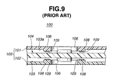
- the disc cartridge 100 comprises a plastic cartridge body 103 and a recording disc 104 rotatably installed in the cartridge body 103.
- the cartridge body 103 comprises upper and lower rectangular half members 101 and 102 that are put and coupled together.
- the recording disc 104 is constructed of a recording medium that can record information signals thereon.
- the cartridge body 103 is formed with a rectangular opening 105 and a semi-circular opening 106 which are mated with each other. That is, the semi-circular opening 106 is provided at a central portion of the cartridge body 103 and the rectangular opening 105 extends radially outward from a peripheral portion of the semi-circular opening 106.
- the rectangular opening 105 is used for exposing the recording disc 104 to a signal recording/reading head of a disc cartridge player, while the semi-circular opening 106 is used for receiving therein a disc table of the disc cartridge player.
- a shutter member 107 is provided to the cartridge body 103 to selectively close and open the two merged openings 105 and 106.
- upper and lower surfaces 103a and 103b of a flat interior of the cartridge body 103 are respectively formed with annular ridges or disc holding portions 108 that extend around the semi-circular opening 106.
- Each disc holding portion 108 has a flat top.
- annular disc bearing members 109 are made of a high polymer material, such as ultrahigh molecular weight polyethylene, polytetrafluoroethylene or the like, which has a high wear and abrasion resistance and a high slip characteristic. Due to usage of such disc bearing members 109, undesired abrasion of the non-recording annular inside area of the recording disc 104, which inevitably occurs when the recording disc 104 is rotated at a high speed, can be minimized.
- a disc cartridge which comprises a cartridge body including upper and lower half members which are put and coupled together; a recording disc rotatably received in the cartridge body, the recording disc including a signal recording annular major area and a non-recording annular inside area; a disc holding portion formed on at least one of inner surfaces of the upper and lower half members, the holding portion having a top that faces the non-recording annular inside area; and a disc bearing member attached to the top of the disc holding portion to bear the non-recording annular inside area, the disc bearing member being made of a porous material that has a high wear and abrasion resistance and a high slip characteristic.
- a disc cartridge which comprises a cartridge body including upper and lower half members which are put and coupled together; a recording disc rotatably received in the cartridge body, the recording disc including a signal recording annular major area and a non-recording annular inside area; upper and lower disc holding portions respectively formed on inner surfaces of the upper and lower half members, the upper and lower disc holding portions having tops face respectively upper and lower surfaces of the non-recording annular inside area of the recording disc; disc bearing members attached to the tops of the upper and lower disc holding portions to bear the upper and lower surfaces of the non-recording annular inside area of the recording disc, wherein each of the disc bearing members is made of a porous material that has a high wear and abrasion resistance and a high slip characteristic.
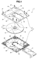
- FIG. 1 of the drawings there is shown an exploded view of a disc cartridge 1 according to a preferred embodiment of the present invention.
- the disc cartridge 1 comprises generally a rectangular cartridge body 4 which is made of a plastic and a recording disc 5 which is rotatably received in the cartridge body 4.
- the cartridge body 4 comprises upper and lower rectangular half members 2 and 3 which are put and coupled together. For the coupling, a plurality of screw bolts 31 are used, as shown.
- the upper and lower rectangular half members 2 and 3 are respectively formed with generally rectangular slots 7 and 8 each extending from a central portion of the half member 2 or 3 toward a front end of the same.
- Each generally rectangular slot 7 or 8 comprises a semi-circular opening 7b or 8b which is formed in the central portion of the half member 2 or 3 and a rectangular opening 7a or 8a which extends outward from a peripheral portion of the semi-circular opening 7b or 8b, as shown.
- the semi-circular openings 7b and 8b are used for receiving therein a disc table of a disc cartridge player (not shown), while the rectangular openings 7a and 8a are used for exposing upper and lower surfaces of the recording disc 5 to a signal recording/reading head of the disc cartridge player.
- the disc table Under operation of the disc cartridge player, the disc table supports a central portion of the recording disc 5 and the signal recording/reading head moves back and forth in the rectangular openings 7a and 7b for scanning the recording surface of the disc 5.
- the recording disc 5 generally comprises a disc proper 51 and a hub member 52 which is installed to a central portion of the disc proper 51.
- the disc proper 51 comprises a signal recording annular major area 5a and a non-recording annular inside area 5b that surrounds the hub member 52.
- a shutter member 9 is provided to the cartridge body 4 to selectively close and open the generally rectangular slots 7 and 8. Usually, the shutter member 9 assumes its close position due to work of a biasing spring installed therein. With this, the interior of the disc cartridge 1 is protected from surrounding dust. While, when the disc cartridge 1 is put into the disc cartridge player, the shutter member 9 is forced to move to its open position.
- the upper and lower rectangular half members 2 and 3 are molded from a thermoplastic resin, such as polycarbonate or the like, which has a sufficient moldability and a satisfied mechanical strength.
- Each half member 2 or 3 has a raised side wall 32 or 33 which extends along a periphery thereof. When these two half members 2 and 3 are properly coupled, these raised side walls 32 and 33 become mated to thereby to constitute a side wall of the produced disc cartridge 1.
- each half member 2 or 3 has an annular raised wall 34 or 35 whose diameter is slightly larger than that of the recording disc 5.
- these annular raised walls 34 and 35 become mated thereby to constitute an annular space in which the recording disc 5 is rotatably received.
- the periphery of the annular space is merged with the side wall of disc cartridge 1 at three points.
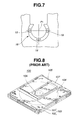
- each half member 2 or 3 is formed around the semi-circular opening 7b or 8b with a semi-circular or horseshoe-shaped disc holding portion 16 that is raised toward the interior of the cartridge body 4.
- each disc holding portion 16 faces the non-recording annular inside area 5b of the recording disc 5. That is, when the two half members 2 and 3 are properly coupled, the two disc holding portions 16 face to each other leaving therebetween a certain space for the recording disc 5.
- each disc holding portion 16 comprises two arcuate ribs 17 that extend in parallel around the semi-circular opening 8b or 7b. Between the two arcuate ribs 17, there is defined an arcuate groove 27. A plurality (five in the illustrated embodiment) of projections 18 are raised from the bottom of the arcuate groove 27, each having a flat top that is flush with the tops of the two arcuate ribs 17. As shown, the projections 18 are arranged at equally spaced intervals.
- a disc bearing member 19 which is circular in shape and has a high wear and abrasion resistance and a high slip characteristic.
- a first group of disc bearing members 19 are arranged in a manner to face the lower surface of the disc 5, and above the recording disc 5 in the cartridge body 4, a second group of disc bearing members 19 are arranged to face the upper surface of the disc 5.
- any adjacent two of the projections 18 formed on each half member 3 or 2 are spaced apart from each other by 60 degrees with respect to a center "P1" of the semi-circular opening 8b or 7b.
- This equally spaced arrangement of the projections 18 brings about easiness with which the disc bearing members 19 are bonded to the tops of the projections 18 automatically. That is, for such bonding, an automatic assembling device is used, that turns the half member 3 or 2 about the center "P1".
- the disc bearing members 19 are stamped out from an ultrahigh molecular weight polyethylene porous sheet.
- the porosity of the sheet is 30%, the average pore size of the same is 30um and the thickness of the same is 0.1 mm.
- the inventor carried out the following production steps, which are depicted in Figs. 4A to 4E.
- a female die 202 was prepared, which had a cylindrical bore. Then, powder 201 of high molecular weight polyethylene was filled into the bore of the female die 202 and heated at a certain temperature to adjust the packing density of the powder 201. Then, as is seen from Fig. 4B, the powder 201 was compacted by a male die 203 while being heated, and then the compacted powder was cooled. Then, the male die 203 was removed from the female die 202 to release the product, that is, a cylindrical compact 204 as is shown in Fig. 4C. The cylindrical compact 204 thus produced showed even porosity therethroughout and ultrahigh molecular weight.
- each disc bearing member 19 showed even porosity therethroughout and ultrahigh molecular weight.
- the disc bearing members 19 are arranged to face the non-recording annular inside area 5b of the recording disc 5. That is, the first and second groups of disc bearing members 19 are arranged to face and contact the lower and upper surfaces of the non-recording annular inside area 5b of the recording disc 5.
- the hub member 52 of the recording disc 5 is formed with a center opening 53.
- a center spindle of the disc table of the player is inserted into the center opening 53 and at the same time the hub member 52 of the recording disc 5 is magnetically fastened to the disc table.
- the conventional disc bearing member 109 was a circular member stamped out from a high molecular weight polyethylene sheet.
- the test device for the friction test is schematically shown in Fig. 5.
- the test device comprises generally a pushing bar having a convex head 301 and a sliding surface 302.
- Two types of sliding surface 302 were used, the first being the naked surface of a 5.25-inch MO disc made of polycarbonate (PC), and the other being a protection film of ultraviolet (UV) curing resin coated on the naked surface of the MO disc.
- each test piece 19 or 109 was bonded to the convex head 301 and pressed against the sliding surface 302 by a force of 50 grams and the sliding surface 302 was moved reciprocatively at a speed of 76mm/sec.
- a friction coefficient was measured on each test piece at the times of zero (start), 10,000, 50,000 and 100,000 reciprocation.
- Test Piece Contacting Surface Friction Coefficient Start 10,000 50,000 100,000 Invention PC Surface 0.16 0.24 0.32 0.4 Protection Film 0.12 0.16 0.16 0.2 Conventional Member PC Surface 0.32 0.32 0.42 0.5 Protection Film 0.16 0.48 0.96 0.64
- the disc bearing member 19 of the invention showed a smaller friction coefficient than the conventional one 109. That is, it was revealed that the disc bearing member 19 of the invention produced only a small friction force when supporting a rotating recording disc 5.
- each projection 18 has the disc bearing member 19 bonded thereto.
- the horseshoe-shaped disc holding portion 16 may have a flat top surface therethroughout onto which a plurality (three in the illustrated example) of disc bearing members 19 are bonded at spaced intervals.
- the disc bearing member 19 may be circular, rectangular or of any shape.
- other known measures, such as welding and the like, may be used for attaching the disc bearing member 19 to the flat top surface of the horseshoe-shaped disc holding portion 16.
- the porous material of the disc bearing member 19 is an ultrahigh molecular weight polyethylene.
- other materials may be also used for the porous material of the disc bearing member 19, which are for example polytetrafluoroethlene, sintered type of this plastic and the like.
- the porosity of the porous ultrahigh molecular weight material should be from 20% to 50%, preferably from 25% (1/4) to 35% (about 1/3), that corresponds to the porosity possessed by a compressed sheet having a half thickness.
- two disc holding portions 16 are provided for holding the recording disc 5.
- only one disc holding portion 16 may be provided depending on the atmosphere where the disc cartridge 1 is practically used.
Landscapes
- Optical Record Carriers And Manufacture Thereof (AREA)
Abstract
Description
| Test Piece | Contacting Surface | Friction Coefficient | |||
| Start | 10,000 | 50,000 | 100,000 | ||
| Invention | PC Surface | 0.16 | 0.24 | 0.32 | 0.4 |
| Protection Film | 0.12 | 0.16 | 0.16 | 0.2 | |
| Conventional Member | PC Surface | 0.32 | 0.32 | 0.42 | 0.5 |
| Protection Film | 0.16 | 0.48 | 0.96 | 0.64 |
Claims (8)
- A disc cartridge, comprising:a cartridge body comprising upper and lower half members;a recording disc rotatably received in said cartridge body, said recording disc including a signal recording annular major area and a non-recording annular inside area;a disc holding portion formed on at least one of the inner surfaces of said upper and lower half members, said disc holding portion having a surface which faces said non-recording annular inside area; anda disc bearing member attached to said surface of said disc holding portion to bear said non-recording annular inside area, said disc bearing member being formed of a porous material that has a high wear and abrasion resistance and a high slip characteristic.
- A disc cartridge as claimed in Claim 1, in which said porous material is a porous sheet of ultrahigh molecular weight polyethylene.
- A disc cartridge as claimed in Claim 1, in which said porous material is a porous sheet of polytetrafluoroethylene.
- A disc cartridge as claimed in Claim 1, in which the porosity of said porous material ranges from 20% to 50%.
- A disc cartridge as claimed in Claim 1, in which said non-recording annular inside area of said recording disc is covered with a protection film of ultraviolet curing resin.
- A disc cartridge, comprising:a cartridge body comprising upper and lower half members;a recording disc rotatably received in said cartridge body, said recording disc including a signal recording annular major area and a non-recording annular inside area;upper and lower disc holding portions respectively formed on the inner surfaces of said upper and lower half members, said upper and lower disc holding portions each having a surface which faces a respective one of the upper and lower surfaces of said non-recording annular inside area of said recording disc; anddisc bearing members attached to said surfaces of said upper and lower disc holding portions to bear said upper and lower surfaces of said non-recording annular inside area of said recording disc;wherein each of said disc bearing members is formed of a porous material that has a high wear and abrasion resistance and a high slip characteristic.
- A disc cartridge as claimed in Claim 6, in which each of said disc bearing members is a member stamped out from an ultrahigh molecular weight polyethylene porous sheet.
- A disc cartridge as claimed in Claim 7, in which said ultrahigh molecular weight polyethylene porous sheet is produced by the steps of:(a) heating and compacting a predetermined amount of powder of high molecular weight polyethylene to produce a shaped compact of porous ultrahigh molecular weight polyethylene; and(b) peeling said shaped compact to produce a long sheet of porous ultrahigh molecular weight polyethylene.
Applications Claiming Priority (2)
| Application Number | Priority Date | Filing Date | Title |
|---|---|---|---|
| JP33226399 | 1999-11-24 | ||
| JP33226399A JP2001148175A (en) | 1999-11-24 | 1999-11-24 | Disk cartridge |
Publications (2)
| Publication Number | Publication Date |
|---|---|
| EP1103971A2 true EP1103971A2 (en) | 2001-05-30 |
| EP1103971A3 EP1103971A3 (en) | 2002-01-02 |
Family
ID=18253000
Family Applications (1)
| Application Number | Title | Priority Date | Filing Date |
|---|---|---|---|
| EP00310155A Withdrawn EP1103971A3 (en) | 1999-11-24 | 2000-11-15 | Disc cartridge |
Country Status (2)
| Country | Link |
|---|---|
| EP (1) | EP1103971A3 (en) |
| JP (1) | JP2001148175A (en) |
Cited By (1)
| Publication number | Priority date | Publication date | Assignee | Title |
|---|---|---|---|---|
| EP1304699A3 (en) * | 2001-10-18 | 2003-08-27 | SAMSUNG ELECTRONICS Co. Ltd. | Disk cartridge |
Families Citing this family (3)
| Publication number | Priority date | Publication date | Assignee | Title |
|---|---|---|---|---|
| JP4549621B2 (en) | 2002-12-02 | 2010-09-22 | 日東電工株式会社 | Crosslinkable polymer-supported porous film for battery separator and battery manufacturing method using the same |
| JP2004310943A (en) | 2003-04-09 | 2004-11-04 | Nitto Denko Corp | Sliding member |
| JP4187751B2 (en) | 2006-03-29 | 2008-11-26 | 日東電工株式会社 | Protective member and optical pickup device using the same |
Family Cites Families (6)
| Publication number | Priority date | Publication date | Assignee | Title |
|---|---|---|---|---|
| JPS6344285U (en) * | 1986-09-09 | 1988-03-24 | ||
| JPS63187430A (en) * | 1987-01-30 | 1988-08-03 | Toshiba Corp | Information recording medium |
| JPH0250376A (en) * | 1988-08-11 | 1990-02-20 | Fujitsu Ltd | Magnetic disk device |
| US5717684A (en) * | 1990-01-29 | 1998-02-10 | Dai Nippon Insatsu Kabushiki Kaisha | Disk cartridge having chamfered wall portion |
| JPH03266274A (en) * | 1990-03-15 | 1991-11-27 | Daicel Chem Ind Ltd | Cartridge for disk |
| JPH09251748A (en) * | 1996-03-13 | 1997-09-22 | Sony Corp | Disk cartridge |
-
1999
- 1999-11-24 JP JP33226399A patent/JP2001148175A/en active Pending
-
2000
- 2000-11-15 EP EP00310155A patent/EP1103971A3/en not_active Withdrawn
Cited By (2)
| Publication number | Priority date | Publication date | Assignee | Title |
|---|---|---|---|---|
| EP1304699A3 (en) * | 2001-10-18 | 2003-08-27 | SAMSUNG ELECTRONICS Co. Ltd. | Disk cartridge |
| US7143427B2 (en) | 2001-10-18 | 2006-11-28 | Samsung Electronics Co., Ltd. | Disk cartridge having a support portion to support the disk |
Also Published As
| Publication number | Publication date |
|---|---|
| JP2001148175A (en) | 2001-05-29 |
| EP1103971A3 (en) | 2002-01-02 |
Similar Documents
| Publication | Publication Date | Title |
|---|---|---|
| NL194653C (en) | Flexible magnetic disk cassette. | |
| KR900004661B1 (en) | Information processing device | |
| US4743994A (en) | Arrangement for positioning a recording disc of a disc cartridge | |
| CN101373615A (en) | Optical data recording medium, reading device, recording device and manufacturing method thereof | |
| US5905606A (en) | High-performance disk drive limit stop employing encapsulated visco-elastic material | |
| EP1103971A2 (en) | Disc cartridge | |
| US20050028182A1 (en) | Turn table and optical disk using the turn table | |
| US6347070B1 (en) | Plastic clamp with hub and platter for use in disc drive | |
| EP0458477A2 (en) | Stabilisation of flexible optical media | |
| US3912282A (en) | Recording and reproducing apparatus using flexible recording media | |
| US6198598B1 (en) | Disc cartridge with slippery film to reduce friction and vent to discharge dust | |
| US5657311A (en) | Disc-shaped recording medium with hub structure | |
| KR100248481B1 (en) | Disk | |
| US6532205B2 (en) | Disk centering apparatus | |
| US6353591B1 (en) | Disk rotating device | |
| JPWO1996021224A1 (en) | disc cartridge | |
| KR100629732B1 (en) | Recording or reproducing apparatus having a holding and removing device for a disc shaped recording medium | |
| RU2007105145A (en) | CONTAINER FOR A DIGITAL RECORDING MEDIA HAVING A DISC FORM | |
| US6568452B1 (en) | Attachment apparatus for disc protective sheet and attachment method therefore | |
| KR0165297B1 (en) | Multi-layered Information Disc and Manufacturing Method Thereof | |
| US20020157579A1 (en) | Turntable for a disc-shaped information carrier and player provided with such a turntable | |
| EP1211684B1 (en) | Method of manufacturing a magnetic disc cartridge | |
| CN1236474A (en) | Disk case | |
| KR0140883B1 (en) | Center core of magnetic disk | |
| WO1998002884A1 (en) | Molded-in lifter for cleaning a flexible magnetic disc |
Legal Events
| Date | Code | Title | Description |
|---|---|---|---|
| PUAI | Public reference made under article 153(3) epc to a published international application that has entered the european phase |
Free format text: ORIGINAL CODE: 0009012 |
|
| AK | Designated contracting states |
Kind code of ref document: A2 Designated state(s): DE FR GB Kind code of ref document: A2 Designated state(s): AT BE CH CY DE DK ES FI FR GB GR IE IT LI LU MC NL PT SE TR |
|
| AX | Request for extension of the european patent |
Free format text: AL;LT;LV;MK;RO;SI |
|
| PUAL | Search report despatched |
Free format text: ORIGINAL CODE: 0009013 |
|
| AK | Designated contracting states |
Kind code of ref document: A3 Designated state(s): AT BE CH CY DE DK ES FI FR GB GR IE IT LI LU MC NL PT SE TR |
|
| AX | Request for extension of the european patent |
Free format text: AL;LT;LV;MK;RO;SI |
|
| 17P | Request for examination filed |
Effective date: 20020613 |
|
| AKX | Designation fees paid |
Free format text: DE FR GB |
|
| 17Q | First examination report despatched |
Effective date: 20040624 |
|
| GRAP | Despatch of communication of intention to grant a patent |
Free format text: ORIGINAL CODE: EPIDOSNIGR1 |
|
| STAA | Information on the status of an ep patent application or granted ep patent |
Free format text: STATUS: THE APPLICATION IS DEEMED TO BE WITHDRAWN |
|
| 18D | Application deemed to be withdrawn |
Effective date: 20060226 |