EP1103811A2 - Process for the continuous determination of the interaction between drilling fluids and shale formations - Google Patents
Process for the continuous determination of the interaction between drilling fluids and shale formations Download PDFInfo
- Publication number
- EP1103811A2 EP1103811A2 EP00204157A EP00204157A EP1103811A2 EP 1103811 A2 EP1103811 A2 EP 1103811A2 EP 00204157 A EP00204157 A EP 00204157A EP 00204157 A EP00204157 A EP 00204157A EP 1103811 A2 EP1103811 A2 EP 1103811A2
- Authority
- EP
- European Patent Office
- Prior art keywords
- shale
- interaction
- preparation
- process according
- drilling
- Prior art date
- Legal status (The legal status is an assumption and is not a legal conclusion. Google has not performed a legal analysis and makes no representation as to the accuracy of the status listed.)
- Withdrawn
Links
- 238000005553 drilling Methods 0.000 title claims abstract description 29
- 239000012530 fluid Substances 0.000 title claims abstract description 27
- 238000000034 method Methods 0.000 title claims abstract description 21
- 230000003993 interaction Effects 0.000 title claims abstract description 15
- 230000015572 biosynthetic process Effects 0.000 title claims abstract description 10
- 238000005755 formation reaction Methods 0.000 title claims abstract description 10
- 238000005259 measurement Methods 0.000 claims abstract description 11
- 238000002360 preparation method Methods 0.000 claims abstract description 11
- 239000000203 mixture Substances 0.000 claims abstract description 8
- 230000005540 biological transmission Effects 0.000 claims abstract description 7
- 230000008961 swelling Effects 0.000 claims abstract description 6
- 238000005520 cutting process Methods 0.000 claims description 21
- 239000011435 rock Substances 0.000 claims description 5
- XLYOFNOQVPJJNP-UHFFFAOYSA-N water Substances O XLYOFNOQVPJJNP-UHFFFAOYSA-N 0.000 claims description 3
- 239000004927 clay Substances 0.000 description 10
- WCUXLLCKKVVCTQ-UHFFFAOYSA-M Potassium chloride Chemical compound [Cl-].[K+] WCUXLLCKKVVCTQ-UHFFFAOYSA-M 0.000 description 7
- FAPWRFPIFSIZLT-UHFFFAOYSA-M Sodium chloride Chemical compound [Na+].[Cl-] FAPWRFPIFSIZLT-UHFFFAOYSA-M 0.000 description 4
- 239000000654 additive Substances 0.000 description 4
- 230000001066 destructive effect Effects 0.000 description 4
- 239000003129 oil well Substances 0.000 description 4
- 230000000694 effects Effects 0.000 description 3
- 238000007373 indentation Methods 0.000 description 3
- 239000001103 potassium chloride Substances 0.000 description 3
- 235000011164 potassium chloride Nutrition 0.000 description 3
- 239000011734 sodium Substances 0.000 description 3
- 239000000243 solution Substances 0.000 description 3
- ZFQCFWRSIBGRFL-UHFFFAOYSA-B 2-hydroxypropane-1,2,3-tricarboxylate;zirconium(4+) Chemical compound [Zr+4].[Zr+4].[Zr+4].[O-]C(=O)CC(O)(CC([O-])=O)C([O-])=O.[O-]C(=O)CC(O)(CC([O-])=O)C([O-])=O.[O-]C(=O)CC(O)(CC([O-])=O)C([O-])=O.[O-]C(=O)CC(O)(CC([O-])=O)C([O-])=O ZFQCFWRSIBGRFL-UHFFFAOYSA-B 0.000 description 2
- 235000015076 Shorea robusta Nutrition 0.000 description 2
- 244000166071 Shorea robusta Species 0.000 description 2
- 230000000052 comparative effect Effects 0.000 description 2
- 150000002148 esters Chemical class 0.000 description 2
- 238000009499 grossing Methods 0.000 description 2
- 239000011780 sodium chloride Substances 0.000 description 2
- 239000004115 Sodium Silicate Substances 0.000 description 1
- 229920006372 Soltex Polymers 0.000 description 1
- 239000008186 active pharmaceutical agent Substances 0.000 description 1
- 230000032683 aging Effects 0.000 description 1
- 239000007864 aqueous solution Substances 0.000 description 1
- 239000001913 cellulose Substances 0.000 description 1
- 229920002678 cellulose Polymers 0.000 description 1
- 238000012512 characterization method Methods 0.000 description 1
- 239000003638 chemical reducing agent Substances 0.000 description 1
- 238000012790 confirmation Methods 0.000 description 1
- 229910003460 diamond Inorganic materials 0.000 description 1
- 239000010432 diamond Substances 0.000 description 1
- 238000009792 diffusion process Methods 0.000 description 1
- 239000002270 dispersing agent Substances 0.000 description 1
- 239000006185 dispersion Substances 0.000 description 1
- 239000000706 filtrate Substances 0.000 description 1
- 238000009472 formulation Methods 0.000 description 1
- 238000005098 hot rolling Methods 0.000 description 1
- 239000003112 inhibitor Substances 0.000 description 1
- 230000002401 inhibitory effect Effects 0.000 description 1
- 230000001788 irregular Effects 0.000 description 1
- 239000000314 lubricant Substances 0.000 description 1
- NTHWMYGWWRZVTN-UHFFFAOYSA-N sodium silicate Chemical compound [Na+].[Na+].[O-][Si]([O-])=O NTHWMYGWWRZVTN-UHFFFAOYSA-N 0.000 description 1
- 229910052911 sodium silicate Inorganic materials 0.000 description 1
- 239000000126 substance Substances 0.000 description 1
- 238000002604 ultrasonography Methods 0.000 description 1
Images


Classifications
-
- G—PHYSICS
- G01—MEASURING; TESTING
- G01N—INVESTIGATING OR ANALYSING MATERIALS BY DETERMINING THEIR CHEMICAL OR PHYSICAL PROPERTIES
- G01N29/00—Investigating or analysing materials by the use of ultrasonic, sonic or infrasonic waves; Visualisation of the interior of objects by transmitting ultrasonic or sonic waves through the object
- G01N29/04—Analysing solids
- G01N29/07—Analysing solids by measuring propagation velocity or propagation time of acoustic waves
-
- G—PHYSICS
- G01—MEASURING; TESTING
- G01N—INVESTIGATING OR ANALYSING MATERIALS BY DETERMINING THEIR CHEMICAL OR PHYSICAL PROPERTIES
- G01N29/00—Investigating or analysing materials by the use of ultrasonic, sonic or infrasonic waves; Visualisation of the interior of objects by transmitting ultrasonic or sonic waves through the object
- G01N29/22—Details, e.g. general constructional or apparatus details
- G01N29/30—Arrangements for calibrating or comparing, e.g. with standard objects
-
- G—PHYSICS
- G01—MEASURING; TESTING
- G01N—INVESTIGATING OR ANALYSING MATERIALS BY DETERMINING THEIR CHEMICAL OR PHYSICAL PROPERTIES
- G01N2291/00—Indexing codes associated with group G01N29/00
- G01N2291/02—Indexing codes associated with the analysed material
- G01N2291/024—Mixtures
- G01N2291/02441—Liquids in porous solids
-
- G—PHYSICS
- G01—MEASURING; TESTING
- G01N—INVESTIGATING OR ANALYSING MATERIALS BY DETERMINING THEIR CHEMICAL OR PHYSICAL PROPERTIES
- G01N2291/00—Indexing codes associated with group G01N29/00
- G01N2291/02—Indexing codes associated with the analysed material
- G01N2291/028—Material parameters
- G01N2291/02827—Elastic parameters, strength or force
-
- G—PHYSICS
- G01—MEASURING; TESTING
- G01N—INVESTIGATING OR ANALYSING MATERIALS BY DETERMINING THEIR CHEMICAL OR PHYSICAL PROPERTIES
- G01N2291/00—Indexing codes associated with group G01N29/00
- G01N2291/04—Wave modes and trajectories
- G01N2291/042—Wave modes
- G01N2291/0421—Longitudinal waves
-
- G—PHYSICS
- G01—MEASURING; TESTING
- G01N—INVESTIGATING OR ANALYSING MATERIALS BY DETERMINING THEIR CHEMICAL OR PHYSICAL PROPERTIES
- G01N2291/00—Indexing codes associated with group G01N29/00
- G01N2291/04—Wave modes and trajectories
- G01N2291/048—Transmission, i.e. analysed material between transmitter and receiver
-
- G—PHYSICS
- G01—MEASURING; TESTING
- G01N—INVESTIGATING OR ANALYSING MATERIALS BY DETERMINING THEIR CHEMICAL OR PHYSICAL PROPERTIES
- G01N2291/00—Indexing codes associated with group G01N29/00
- G01N2291/10—Number of transducers
- G01N2291/102—Number of transducers one emitter, one receiver
Definitions
- the present invention relates to a process for the continuous determination of the interaction between drilling fluids and shale formations.
- the present invention relates to a process for continuously verifying the effect of drilling fluids on the stability of shale formations in oil wells drilling, by measuring the ultrasonic wave transmission velocity on clay cuttings subjected to aging in drilling fluids.
- drilling fluids are prepared with additives suitable for maintaining (or if possible improving) the mechanical properties of the shales and inhibiting swelling.
- the effectiveness of these additives is evaluated by tests which are specified in API procedures, for example, dispersion tests of clay cuttings in mud (hot-rolling test) or laboratory procedures (for example measuring the swelling of clay samples).
- tests which are specified in API procedures for example, dispersion tests of clay cuttings in mud (hot-rolling test) or laboratory procedures (for example measuring the swelling of clay samples).
- techniques for evaluating the mechanical characteristics have the great disadvantage of being destructive, costly and time-consuming.
- a process has now been found which overcomes the above disadvantages, as it allows the mechanical properties of shales to be evaluated in the presence of drilling fluids in relation to the interaction time.
- the process of the present invention also has the advantage of not being destructive.
- the present invention relates to a process for the continuous determination of the interaction between drilling fluids and shale formations, which comprises:
- the process of the present invention can be applied to cuttings produced during drilling, or to shale samples prepared by suitably cutting well or outcrop cores. Alternatively, it is possible to operate on reconstituted shale samples.
- step a The water- or oil-based drilling fluids and relative preparation (step a) are well-known to experts in the field (see for example Gray G.R. and Darley H.C.H.: “Composition and properties of oil well drilling fluids”; Gulf Publishing Company, fourth edition, Houston TX U.S.A., 1980).
- Step (b) of the process of the present invention consists in the preparation of the shale sample. This is carried out by cutting suitably-sized (at least 2 mm thick) test-samples. When cuttings are used, these can either derive from wells or be prepared from cores (well or outcrop). Cutting are normally prepared with an automatic slitter in demineralized water or oil to obtain the desired test-samples, which must have at least two flat, parallel surfaces. Those which have cracks are discharged. It is essential for them not to be exposed to the air as the response of the sample greatly depends on the degree of saturation. When well cuttings are used, owing to their irregular geometry, they must be subjected to smoothing or cutting until two flat, parallel surfaces are obtained. This can be achieved by smoothing each cutting by means of a diamond sandpaper disks lubricated with oil or demineralized water, until two flat, parallel surfaces are obtained.
- Step (c) consists in preparing the mixture of (a) + (b), preferably prepared by pouring (b) into (a), under the desired temperature conditions, indicatively from 5°C to 90°C, preferably from 20°C to 60°C.
- step (d) the continuous measurement of the compressional wave transmission velocity is carried out on clay cuttings immersed in a fluid (drilling mud or other).
- a fluid drilling mud or other.
- the clay cutting is placed inside the container filled with the fluid with which it interacts, and set on the signal emitter transducer.
- the other transducer (which acts as emitter and receiver) is placed near the other side of the cutting.
- Variations in these measurements indicate complete interaction between fluid and shale.
- the variation in the velocity in the clay cutting indicates a variation in its mechanical properties. This is confirmed by comparison with the mechanical indentation index values measured on the same shale cuttings subjected to interaction.
- a comparative example is provide to sustain this confirmation.
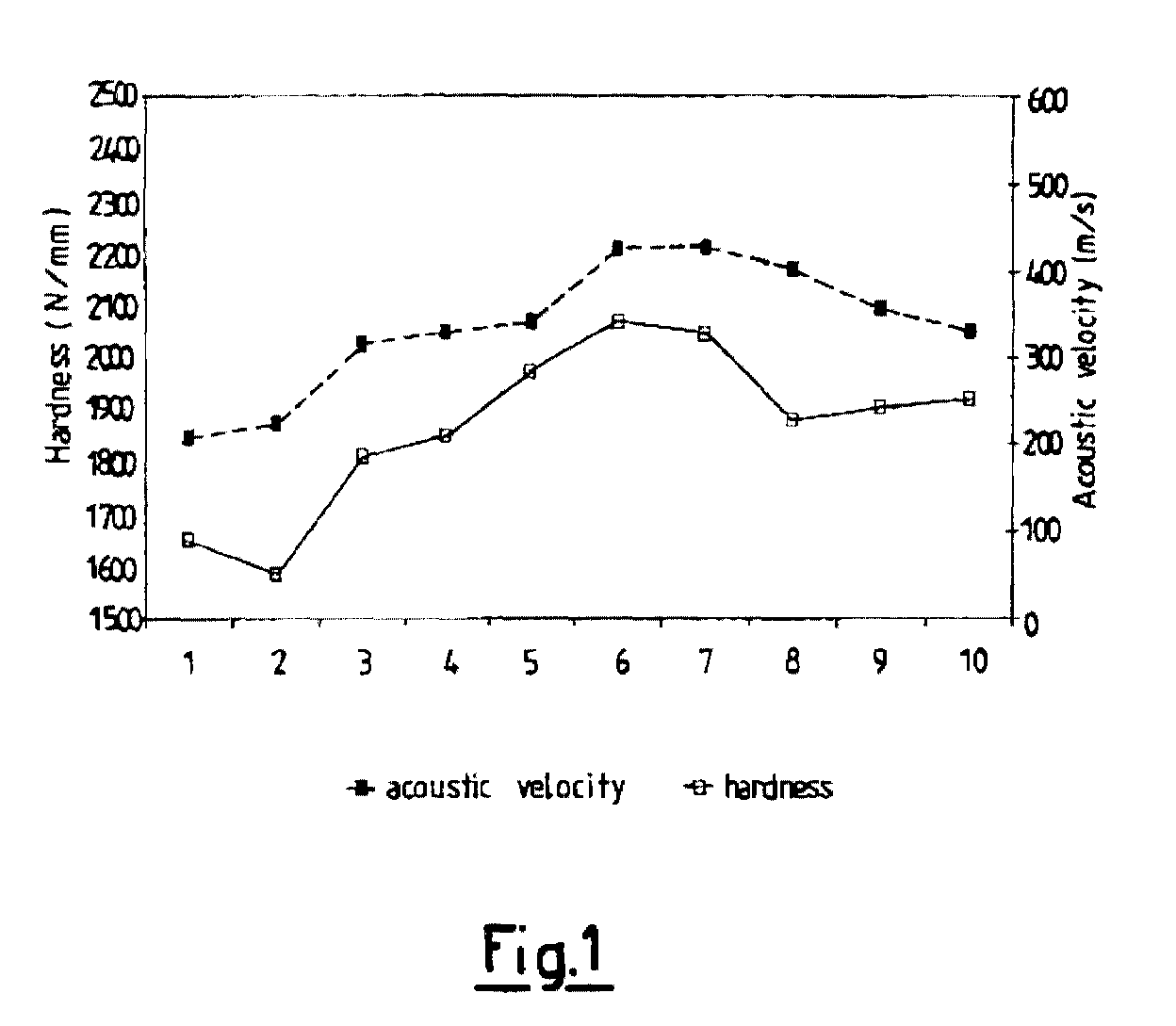
- Figure 1 indicates the acoustic velocity values obtained according to the process of the present invention, of samples of Pierre Shale 2 aged in the solutions specified in the table.
- the same figure indicates, for comparative purposes, the hardness values obtained with a destructive test, i.e. with the indentation test, on the same samples of Pierre Shale 2 on which acoustic measurements had been previously run [the indentation test is carried out by measuring the force applied to a point with a diameter of 1 mm to penetrate the shale by 0.3 mm at a rate of 0.01 mm/s and gives a direct indication of the hardness of the rock, and consequently of the mechanical stability of the shale formation].
- Sample # Composition (concentration additives in wt %) silicate- Na soltex-Na ZRC pac-lv ester KCl 1 0 0 0.6 1 0.4 0 2 0 6 0 0 0 0 3 0 6 0 1 0 10 4 0 6 0.6 0 0.4 10 5 10 0 0 0 0 0 6 10 0 0 1 0.4 10 7 10 0 0.6 0 0 10 8 10 6 0 0 0.4 10 9 10 6 0 1 0.4 0 10 10 6 0.6 0 0 0 0 0 0 0 0
- Figure 2 indicates the trend of the compressional wave transmission velocities through two cuttings of Pierre Shale 2 immersed in two different aqueous solutions, specifically 11% of Sodium Chloride solution (NaCl) and 10% of Potassium Chloride (KCl).
- NaCl Sodium Chloride solution
- KCl Potassium Chloride
- the trend shows how the interaction takes place during the first 5-6 hours, and is then stabilized. This result agrees with what is calculated by means of the diffusion coefficient of a fluid inside the Pierre Shale 2 clay (the size of the samples is a 5 mm-side cube).
- the trend of the velocity variation through samples of Pierre Shale 2 in contact with the two different fluids also indicates different effects (increase in the one case and decrease in the other) on the mechanical properties following said physico-chemical interactions.
Landscapes
- Physics & Mathematics (AREA)
- Health & Medical Sciences (AREA)
- Life Sciences & Earth Sciences (AREA)
- Chemical & Material Sciences (AREA)
- Analytical Chemistry (AREA)
- Biochemistry (AREA)
- General Health & Medical Sciences (AREA)
- General Physics & Mathematics (AREA)
- Immunology (AREA)
- Pathology (AREA)
- Acoustics & Sound (AREA)
- Investigating Or Analyzing Materials By The Use Of Ultrasonic Waves (AREA)
- Investigating Or Analysing Biological Materials (AREA)
- Investigating Or Analyzing Materials By The Use Of Electric Means (AREA)
Abstract
Description
- The present invention relates to a process for the continuous determination of the interaction between drilling fluids and shale formations.
- More specifically, the present invention relates to a process for continuously verifying the effect of drilling fluids on the stability of shale formations in oil wells drilling, by measuring the ultrasonic wave transmission velocity on clay cuttings subjected to aging in drilling fluids.
- During the drilling of an oil well, there is often the problem of instability of the well in shale formations. To prevent this instability, drilling fluids are prepared with additives suitable for maintaining (or if possible improving) the mechanical properties of the shales and inhibiting swelling. The effectiveness of these additives is evaluated by tests which are specified in API procedures, for example, dispersion tests of clay cuttings in mud (hot-rolling test) or laboratory procedures (for example measuring the swelling of clay samples). On the other hand, techniques for evaluating the mechanical characteristics (for example uniaxial or triaxial creep tests) have the great disadvantage of being destructive, costly and time-consuming.
- None of these techniques used in the prior art consider the possibility of analyzing the mechanical behaviour of shale interacting with a drilling fluid in relation to time, a fundamental factor in evaluating the arising of instability in shale formations during the drilling of oil wells.
- It is also known that the relative mechanical properties can be determined from the velocity of sound waves through rock samples. Although these acoustic techniques are not destructive, they have the drawback of being used at present only for the acoustic characterization of formations and although they detect the mechanical properties of the rock, they neglect, on the other hand, the effect due to rock-drilling fluid interaction.
- A process has now been found which overcomes the above disadvantages, as it allows the mechanical properties of shales to be evaluated in the presence of drilling fluids in relation to the interaction time. The process of the present invention also has the advantage of not being destructive.
- In accordance with this, the present invention relates to a process for the continuous determination of the interaction between drilling fluids and shale formations, which comprises:
- (a) preparation of a water- or oil-based drilling fluid;
- (b) preparation of a shale sample having at least two flat, parallel opposite surfaces;
- (c) preparation of the mixture of (b) and (a);
- (d) continuous measurement of the ultrasonic wave transmission velocity through the sample (c), and variations in thickness (swelling and shrinking) of the shale sample, due to interaction with the drilling fluid (a).
-
- The process of the present invention can be applied to cuttings produced during drilling, or to shale samples prepared by suitably cutting well or outcrop cores. Alternatively, it is possible to operate on reconstituted shale samples.
- The water- or oil-based drilling fluids and relative preparation (step a) are well-known to experts in the field (see for example Gray G.R. and Darley H.C.H.: "Composition and properties of oil well drilling fluids"; Gulf Publishing Company, fourth edition, Houston TX U.S.A., 1980).
- Step (b) of the process of the present invention consists in the preparation of the shale sample. This is carried out by cutting suitably-sized (at least 2 mm thick) test-samples. When cuttings are used, these can either derive from wells or be prepared from cores (well or outcrop). Cutting are normally prepared with an automatic slitter in demineralized water or oil to obtain the desired test-samples, which must have at least two flat, parallel surfaces. Those which have cracks are discharged. It is essential for them not to be exposed to the air as the response of the sample greatly depends on the degree of saturation. When well cuttings are used, owing to their irregular geometry, they must be subjected to smoothing or cutting until two flat, parallel surfaces are obtained. This can be achieved by smoothing each cutting by means of a diamond sandpaper disks lubricated with oil or demineralized water, until two flat, parallel surfaces are obtained.
- Step (c) consists in preparing the mixture of (a) + (b), preferably prepared by pouring (b) into (a), under the desired temperature conditions, indicatively from 5°C to 90°C, preferably from 20°C to 60°C.
- In step (d) the continuous measurement of the compressional wave transmission velocity is carried out on clay cuttings immersed in a fluid (drilling mud or other). The equipment used is indicated, for illustrative purposes but without limiting the scope of the invention, in Figure A.
- The clay cutting is placed inside the container filled with the fluid with which it interacts, and set on the signal emitter transducer. The other transducer (which acts as emitter and receiver) is placed near the other side of the cutting. With this configuration, it is possible to run two simultaneous measurements whose combined results enable two values to be determined:
- a) the transit time of the ultrasounds reflected by the surface of the cutting (in Figure A indicated by 1) from which the variations in the thickness of the cutting are continuously determined during the interaction test (possible swelling or shrinking measurement of the clay);
- b) the transit time through the clay cutting (in Figure A indicated by 2) from which the compressional wave transmission velocity measurement is continuously obtained.
-
- Variations in these measurements indicate complete interaction between fluid and shale. The variation in the velocity in the clay cutting indicates a variation in its mechanical properties. This is confirmed by comparison with the mechanical indentation index values measured on the same shale cuttings subjected to interaction. A comparative example is provide to sustain this confirmation.
- The following examples are provided for a better understanding of the present invention.
- Figure 1 indicates the acoustic velocity values obtained according to the process of the present invention, of samples of Pierre Shale 2 aged in the solutions specified in the table. The same figure indicates, for comparative purposes, the hardness values obtained with a destructive test, i.e. with the indentation test, on the same samples of Pierre Shale 2 on which acoustic measurements had been previously run [the indentation test is carried out by measuring the force applied to a point with a diameter of 1 mm to penetrate the shale by 0.3 mm at a rate of 0.01 mm/s and gives a direct indication of the hardness of the rock, and consequently of the mechanical stability of the shale formation].
- A good correspondence is observed between acoustic velocity and hardness of the cutting for the various samples aged in the solutions specified in the table. This indicates that the acoustic velocity measurements can be used to evaluate the mechanical characteristics of shale and consequently evaluate the impact of the drilling fluid on the stability of the drilling well walls.
Sample # Composition (concentration additives in wt %) silicate- Na soltex-Na ZRC pac- lv ester KCl 1 0 0 0.6 1 0.4 0 2 0 6 0 0 0 0 3 0 6 0 1 0 10 4 0 6 0.6 0 0.4 10 5 10 0 0 0 0 0 6 10 0 0 1 0.4 10 7 10 0 0.6 0 0 10 8 10 6 0 0 0.4 10 9 10 6 0 1 0.4 0 10 10 6 0.6 0 0 0 - The additives used in the formulation of the drilling fluid, indicated below, were subdivided into use classification.
-
- Avasilix® 22, AVA: sodium silicate (Silicate-Na);
- Soltex®, AVA: modified asphaltene (Soltex-Na);
- KCl
-
- Rheomate®, Lamberti: Zirconium citrate (ZRC)
-
- PAC-LV, Baroid: polyanionic cellulose
-
- Avagreen Biolube, AVA: ester.
- Figure 2 indicates the trend of the compressional wave transmission velocities through two cuttings of Pierre Shale 2 immersed in two different aqueous solutions, specifically 11% of Sodium Chloride solution (NaCl) and 10% of Potassium Chloride (KCl). The trend shows how the interaction takes place during the first 5-6 hours, and is then stabilized. This result agrees with what is calculated by means of the diffusion coefficient of a fluid inside the Pierre Shale 2 clay (the size of the samples is a 5 mm-side cube). The trend of the velocity variation through samples of Pierre Shale 2 in contact with the two different fluids also indicates different effects (increase in the one case and decrease in the other) on the mechanical properties following said physico-chemical interactions.
Claims (6)
- A process for the continuous determination of the interaction between drilling fluids and shale formations, which comprises:(a) preparation of a water- or oil-based drilling fluid;(b) preparation of a shale sample having at least two flat, parallel opposite surfaces;(c) preparation of the mixture of (b) and (a);(d) continuous measurement of the ultrasonic wave transmission velocity through the sample (c), and variations in thickness (swelling and shrinking) of the shale sample, due to interaction with the drilling fluid (a).
- The process according to claim 1, characterized in that the shale sample (b) is selected from cuttings produced during drilling, rock samples prepared from well or outcrop cores, reconstituted rock samples.
- The process according to claim 1, characterized in that the drilling fluids are water-based.
- The process according to claim 1, characterized in that it is carried out at a temperature ranging from 5°C to 90°C.
- The process according to claim 4, characterized in that the temperature ranges from 20°C to 60°C.
- The process according to claim 1, characterized in that the measurement (d) is effected using a container inside which the mixture of (a) + (b), an ultrasonic wave emitter and receiver, an ultrasonic wave emitter are placed, outside the above container, there being a signal generator and a wave analyzer.
Applications Claiming Priority (2)
| Application Number | Priority Date | Filing Date | Title |
|---|---|---|---|
| IT1999MI002476A IT1313693B1 (en) | 1999-11-26 | 1999-11-26 | PROCEDURE TO CONTINUOUSLY DETERMINE THE INTERACTION BETWEEN PERFORATION FLUIDS AND CLAY TRAINING. |
| ITMI992476 | 1999-11-26 |
Publications (2)
| Publication Number | Publication Date |
|---|---|
| EP1103811A2 true EP1103811A2 (en) | 2001-05-30 |
| EP1103811A3 EP1103811A3 (en) | 2005-01-12 |
Family
ID=11384033
Family Applications (1)
| Application Number | Title | Priority Date | Filing Date |
|---|---|---|---|
| EP00204157A Withdrawn EP1103811A3 (en) | 1999-11-26 | 2000-11-23 | Process for the continuous determination of the interaction between drilling fluids and shale formations |
Country Status (4)
| Country | Link |
|---|---|
| US (1) | US6430994B1 (en) |
| EP (1) | EP1103811A3 (en) |
| IT (1) | IT1313693B1 (en) |
| NO (1) | NO20005971L (en) |
Cited By (1)
| Publication number | Priority date | Publication date | Assignee | Title |
|---|---|---|---|---|
| CN109828032A (en) * | 2019-02-25 | 2019-05-31 | 山东科技大学 | Prestressing force rotation wetting acoustic sensitivity monitor |
Families Citing this family (6)
| Publication number | Priority date | Publication date | Assignee | Title |
|---|---|---|---|---|
| US7372507B2 (en) * | 2005-02-08 | 2008-05-13 | Texas Instruments Incorporated | Real-time content based gamma adjustment for digital video display |
| US9222350B2 (en) | 2011-06-21 | 2015-12-29 | Diamond Innovations, Inc. | Cutter tool insert having sensing device |
| US20140373619A1 (en) * | 2013-06-19 | 2014-12-25 | Weatherford/Lamb, Inc. | Method and apparatus for measuring deformation of elastomeric materials |
| CN104569149B (en) * | 2013-10-27 | 2017-06-06 | 中国石油化工集团公司 | A kind of drilling fluid inhibition evaluation method |
| CN103837598B (en) * | 2014-03-20 | 2016-05-18 | 西南石油大学 | Mud shale water suction forward position, a kind of down-hole testing arrangement |
| CN104101649B (en) * | 2014-06-17 | 2016-08-17 | 南京大学 | Utilize the method that the velocity of sound judges the content of organic matter in shale |
Family Cites Families (6)
| Publication number | Priority date | Publication date | Assignee | Title |
|---|---|---|---|---|
| FR2667155B1 (en) * | 1990-09-24 | 1993-05-21 | Centre Nat Rech Scient | METHOD AND DEVICE FOR MEASURING THE CONCENTRATION OF AT LEAST TWO FLUIDS IN A POROUS MEDIUM. |
| US5345819A (en) * | 1990-10-22 | 1994-09-13 | Chevron Research And Technology Company | Method and apparatus for wellbore stability analysis |
| US5265461A (en) * | 1991-03-19 | 1993-11-30 | Exxon Production Research Company | Apparatuses and methods for measuring ultrasonic velocities in materials |
| FR2708742B1 (en) * | 1993-07-29 | 1995-09-01 | Inst Francais Du Petrole | Method and device for measuring physical parameters of porous samples wettable by fluids. |
| US5511615A (en) * | 1994-11-07 | 1996-04-30 | Phillips Petroleum Company | Method and apparatus for in-situ borehole stress determination |
| US5741971A (en) * | 1996-01-17 | 1998-04-21 | Bj Services Company | Method for analyzing physical properties of materials |
-
1999
- 1999-11-26 IT IT1999MI002476A patent/IT1313693B1/en active
-
2000
- 2000-11-23 EP EP00204157A patent/EP1103811A3/en not_active Withdrawn
- 2000-11-24 NO NO20005971A patent/NO20005971L/en not_active Application Discontinuation
- 2000-11-27 US US09/721,649 patent/US6430994B1/en not_active Expired - Fee Related
Non-Patent Citations (1)
| Title |
|---|
| NES O.-M. ET AL: "Rig-site and laboratory use of CWT acoustic velocity measurements on cuttings", PROC EUR PET CONF, 1996, pages 349 - 356, XP002229036 * |
Cited By (2)
| Publication number | Priority date | Publication date | Assignee | Title |
|---|---|---|---|---|
| CN109828032A (en) * | 2019-02-25 | 2019-05-31 | 山东科技大学 | Prestressing force rotation wetting acoustic sensitivity monitor |
| CN109828032B (en) * | 2019-02-25 | 2021-07-09 | 山东科技大学 | Prestressed Rotary Wetting Acoustic Sensitivity Monitor |
Also Published As
| Publication number | Publication date |
|---|---|
| IT1313693B1 (en) | 2002-09-09 |
| NO20005971D0 (en) | 2000-11-24 |
| EP1103811A3 (en) | 2005-01-12 |
| ITMI992476A0 (en) | 1999-11-26 |
| US6430994B1 (en) | 2002-08-13 |
| ITMI992476A1 (en) | 2001-05-26 |
| NO20005971L (en) | 2001-05-28 |
Similar Documents
| Publication | Publication Date | Title |
|---|---|---|
| Zhang et al. | Factors determining Poisson’s ratio | |
| Winkler | Frequency dependent ultrasonic properties of high‐porosity sandstones | |
| Sayers et al. | Ultrasonic propagation through hydrating cements | |
| Van Kuijk et al. | A novel ultrasonic cased-hole imager for enhanced cement evaluation | |
| AU2021202822B2 (en) | A method of identifying a material and/or condition of a material in a borehole | |
| CA2529173C (en) | Determination of the impedance of a material behind a casing combining two sets of ultrasonic measurements | |
| US6430994B1 (en) | Process for the continuous determination of the interaction between drilling fluids and shale formations | |
| Nes et al. | Rig site and laboratory use of CWT acoustic velocity measurements on cuttings | |
| Hu et al. | Stress-associated intrinsic and scattering attenuation from laboratory ultrasonic measurements on shales | |
| Jutten et al. | Relationship between cement slurry composition, mechanical properties, and cement-bond-log output | |
| EP0717272B1 (en) | Method for measuring the propagation velocity of ultrasonic acoustic waves through rock fragments | |
| US6435021B1 (en) | Process for verifying the effectiveness of drilling fluids in stabilizing oil well walls | |
| Sothcott et al. | The influence of two different pore fluids on the acoustic properties of reservoir sandstones at sonic and ultrasonic frequencies | |
| Abbas et al. | Laboratory geomechanical characterization of the Zubair shale formation | |
| Abugharara et al. | Baseline Development of Rock Anisotropy Investigation Utilizing Empirical Relationships Between Oriented Physical and Mechanical Measurements and Drilling Performance | |
| Tang et al. | Logging while drilling acoustic measurement in unconsolidated slow formations | |
| Prasad | Drillability of a rock in terms of its physico-mechanical and micro-structural properties | |
| Robinson | Effect of hardness reducers on failure characteristics of rock | |
| New et al. | The transmission of compressional waves in jointed rock | |
| Abugharara et al. | Implementation of circular wave measurements and multiple drilling parameter analysis in rock anisotropy evaluation | |
| Siggins et al. | Stress path, pore pressure and microstructural influences on Q in Carnarvon Basin Sandstones | |
| Wan et al. | Study on the influence of drilling fluid soaking on rock acoustic and mechanical properties | |
| Khan et al. | A non-destructive method for mapping formation damage | |
| CN118815442A (en) | Rock drillability evaluation method based on well logging data | |
| Goueygou et al. | Measurement of ultrasonic attenuation and Rayleigh wave dispersion for testing concrete with subsurface damage |
Legal Events
| Date | Code | Title | Description |
|---|---|---|---|
| PUAI | Public reference made under article 153(3) epc to a published international application that has entered the european phase |
Free format text: ORIGINAL CODE: 0009012 |
|
| AK | Designated contracting states |
Kind code of ref document: A2 Designated state(s): AT BE CH CY DE DK ES FI FR GB GR IE IT LI LU MC NL PT SE TR |
|
| AX | Request for extension of the european patent |
Free format text: AL PAYMENT 20001123;LT PAYMENT 20001123;LV PAYMENT 20001123;MK PAYMENT 20001123;RO PAYMENT 20001123;SI PAYMENT 20001123 |
|
| PUAL | Search report despatched |
Free format text: ORIGINAL CODE: 0009013 |
|
| AK | Designated contracting states |
Kind code of ref document: A3 Designated state(s): AT BE CH CY DE DK ES FI FR GB GR IE IT LI LU MC NL PT SE TR |
|
| AX | Request for extension of the european patent |
Extension state: AL LT LV MK RO SI |
|
| 17P | Request for examination filed |
Effective date: 20050627 |
|
| AKX | Designation fees paid |
Designated state(s): AT BE CH CY DE DK ES FI FR GB GR IE IT LI LU MC NL PT SE TR |
|
| AXX | Extension fees paid |
Extension state: SI Payment date: 20001123 Extension state: RO Payment date: 20001123 Extension state: MK Payment date: 20001123 Extension state: LV Payment date: 20001123 Extension state: LT Payment date: 20001123 Extension state: AL Payment date: 20001123 |
|
| 17Q | First examination report despatched |
Effective date: 20060913 |
|
| STAA | Information on the status of an ep patent application or granted ep patent |
Free format text: STATUS: THE APPLICATION IS DEEMED TO BE WITHDRAWN |
|
| 18D | Application deemed to be withdrawn |
Effective date: 20070324 |