EP1103735A1 - Universal joint - Google Patents
Universal joint Download PDFInfo
- Publication number
- EP1103735A1 EP1103735A1 EP00309688A EP00309688A EP1103735A1 EP 1103735 A1 EP1103735 A1 EP 1103735A1 EP 00309688 A EP00309688 A EP 00309688A EP 00309688 A EP00309688 A EP 00309688A EP 1103735 A1 EP1103735 A1 EP 1103735A1
- Authority
- EP
- European Patent Office
- Prior art keywords
- guide means
- rotation guide
- universal joint
- bearing
- roller rolling
- Prior art date
- Legal status (The legal status is an assumption and is not a legal conclusion. Google has not performed a legal analysis and makes no representation as to the accuracy of the status listed.)
- Granted
Links
Images



Classifications
-
- F—MECHANICAL ENGINEERING; LIGHTING; HEATING; WEAPONS; BLASTING
- F16—ENGINEERING ELEMENTS AND UNITS; GENERAL MEASURES FOR PRODUCING AND MAINTAINING EFFECTIVE FUNCTIONING OF MACHINES OR INSTALLATIONS; THERMAL INSULATION IN GENERAL
- F16D—COUPLINGS FOR TRANSMITTING ROTATION; CLUTCHES; BRAKES
- F16D3/00—Yielding couplings, i.e. with means permitting movement between the connected parts during the drive
- F16D3/16—Universal joints in which flexibility is produced by means of pivots or sliding or rolling connecting parts
- F16D3/20—Universal joints in which flexibility is produced by means of pivots or sliding or rolling connecting parts one coupling part entering a sleeve of the other coupling part and connected thereto by sliding or rolling members
-
- F—MECHANICAL ENGINEERING; LIGHTING; HEATING; WEAPONS; BLASTING
- F16—ENGINEERING ELEMENTS AND UNITS; GENERAL MEASURES FOR PRODUCING AND MAINTAINING EFFECTIVE FUNCTIONING OF MACHINES OR INSTALLATIONS; THERMAL INSULATION IN GENERAL
- F16C—SHAFTS; FLEXIBLE SHAFTS; ELEMENTS OR CRANKSHAFT MECHANISMS; ROTARY BODIES OTHER THAN GEARING ELEMENTS; BEARINGS
- F16C11/00—Pivots; Pivotal connections
- F16C11/04—Pivotal connections
- F16C11/06—Ball-joints; Other joints having more than one degree of angular freedom, i.e. universal joints
-
- F—MECHANICAL ENGINEERING; LIGHTING; HEATING; WEAPONS; BLASTING
- F16—ENGINEERING ELEMENTS AND UNITS; GENERAL MEASURES FOR PRODUCING AND MAINTAINING EFFECTIVE FUNCTIONING OF MACHINES OR INSTALLATIONS; THERMAL INSULATION IN GENERAL
- F16M—FRAMES, CASINGS OR BEDS OF ENGINES, MACHINES OR APPARATUS, NOT SPECIFIC TO ENGINES, MACHINES OR APPARATUS PROVIDED FOR ELSEWHERE; STANDS; SUPPORTS
- F16M11/00—Stands or trestles as supports for apparatus or articles placed thereon ; Stands for scientific apparatus such as gravitational force meters
- F16M11/02—Heads
- F16M11/04—Means for attachment of apparatus; Means allowing adjustment of the apparatus relatively to the stand
- F16M11/06—Means for attachment of apparatus; Means allowing adjustment of the apparatus relatively to the stand allowing pivoting
- F16M11/12—Means for attachment of apparatus; Means allowing adjustment of the apparatus relatively to the stand allowing pivoting in more than one direction
- F16M11/121—Means for attachment of apparatus; Means allowing adjustment of the apparatus relatively to the stand allowing pivoting in more than one direction constituted of several dependent joints
- F16M11/123—Means for attachment of apparatus; Means allowing adjustment of the apparatus relatively to the stand allowing pivoting in more than one direction constituted of several dependent joints the axis of rotation intersecting in a single point, e.g. by using gimbals
-
- Y—GENERAL TAGGING OF NEW TECHNOLOGICAL DEVELOPMENTS; GENERAL TAGGING OF CROSS-SECTIONAL TECHNOLOGIES SPANNING OVER SEVERAL SECTIONS OF THE IPC; TECHNICAL SUBJECTS COVERED BY FORMER USPC CROSS-REFERENCE ART COLLECTIONS [XRACs] AND DIGESTS
- Y10—TECHNICAL SUBJECTS COVERED BY FORMER USPC
- Y10T—TECHNICAL SUBJECTS COVERED BY FORMER US CLASSIFICATION
- Y10T403/00—Joints and connections
- Y10T403/32—Articulated members
Definitions
- the present invention relates to a universal joint to be used for, for example, a parallel link mechanism.
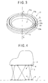
- FIG. 4 represents a driving simulation device utilizing such parallel link mechanism.
- a six actuators such as links 3 are disposed between the base 1 and the jolty table 2, and a jolt is imparted to the jolty table 2 by selectively expanding or contracting the respective actuators so as to control a cubic (i.e. three-dimensional) position and posture thereof.
- the jolty table 2 has three degrees of freedom to determine the position thereof and three degrees of freedom to determine the posture thereof.
- the jolty table has six degrees of freedom in total.
- a joint 4 interposed between both the end portions of the parallel link mechanism 3 and the base 1 or jolty table 2 there are known, as shown in FIGs. 5 and 6, a spherical bearing 5 allowing a spherical motion of the link 3 (FIG. 5) and a universal joint 6 allowing a variation of intersecting angle of the link 3 with respect to the base 1 or jolty table 2 (FIG. 6).
- the spherical bearing 5 is a bearing supporting a spherical journal provided for the end portion of the link 3 and has three degrees of rotational freedom, and because of this structure, the spherical bearing 5 can be smoothly operated at a time of determining the position and posture of the jolty table 2.
- the universal joint 6 is composed of a known structure including a joint body 9 having a yoke 8, a cross fitting 10 and a bearing member disposed between the yoke 8 and the joint body 9, and such universal joint 6 has two degrees of rotational freedom.
- the universal joint 6 it is possible to make large the sway angle ⁇ of the link 3.
- the universal joint 6 has only two degrees of rotational freedom, the number of the degree of the rotational freedom is insufficient for finely determining the position and posture of the jolty table 2, and accordingly, there may cause a case that smooth operation for determining the position and posture of the jolty table 2 cannot be expected.
- An object of the present invention is to substantially eliminate defects or drawbacks encountered in the prior art mentioned above and to provide a universal joint for a parallel link mechanism capable of making smooth operation thereof, allowing a link to have a large sway angle and having a high rigidity to bear an axial load of the link.
- a universal joint comprising:
- first, second and third rotation guide means have rotational center lines, respectively, which intersect each other at one point.
- the third rotation guide means guides a shaft member, of a mechanism to which the universal joint is applied, intersecting the rotational center line of the third rotation guide means at an acute angle, the rotational center lines of the second and third rotation guide means intersect each other at an acute angle, and a space is formed around the rotational center line of the third rotation guide means so that the shaft is allowed to turn full circle.
- the mechanism may preferably be a parallel link mechanism.
- At least one of the first, second and third rotation guide means comprises an outer ring having an inner peripheral surface to which a V-shaped roller rolling groove is formed, an inner ring fitted to the outer ring and having an outer peripheral surface to which a V-shaped groove roller rolling groove is formed and a number of rollers accommodated in a roller rolling passage formed in combination between the roller rolling grooves so that rotation axes of adjacent rollers are normal to each other.
- first connection member connecting the first and second rotation guide means and a second connection member connecting the second and third rotation guide means.
- the first connection member has a bowl shape having an edge portion to which the second rotation guide means is mounted, the edge portion having an inclined surface.
- the second connection member has a pair of connection pieces one of which has an inclined edge portion to which one surface of the third guide means is connected and another one of which has an inclined edge portion to which another surface of the third guide means is connected.
- each of the respective rotation guide means has one degree of rotational freedom, and for example, ball-and-roller bearing, thrust bearing, swiveling bearing, curvilinear guide means or the like may be utilized therefor.
- first, second and third rotation guide means have rotational center lines, respectively, which intersect each other at one point, the posture of such as link can be effectively changed in the three-dimensional direction about the intersecting point being the center thereof.
- the shaft of the link mechanism for example, connected to the universal joint can be rotated by 360° , and hence, the wide sway angle of the shaft member can be ensured.
- At least one of the first, second and third rotation guide means comprises an outer ring having an inner peripheral surface to which a V-shaped roller rolling groove is formed, an inner ring fitted to the outer ring and having an outer peripheral surface to which a V-shaped roller rolling groove is formed and a number of rollers accommodated in the roller rolling passage formed by these roller rolling grooves.
- rollers have rolling contact between the V-shaped roller rolling grooves, and the inner and outer rings does not have sliding contact, it is not necessary to form any play between the inner and outer rings. And friction resistance due to the rolling motion of rollers is small, so that wearing (friction), heat or the like hardly occur, thus being advantageous.
- a universal joint 11 shown in FIG. 1 is one usable for a parallel link mechanism having a structure, for example, that a plurality of links are disposed between a base and a jolty table. And both end portions of the links are connected to the base or jolty table by universal joints 11,11.
- the universal joint 11 is provided with a Pa axis swiveling (turning) bearing 20 as a first rotation guide means, a Pb axis swiveling (turning) bearing 21 as a second rotation guide means which is rotatably guided by the Pa axis swiveling bearing 20 and a PC axis swiveling (turning) bearing 22 as a third rotation guide means which is rotatably guided by the Pb axis swiveling bearing 21.
- the respective swiveling bearings 20, 21 and 22 have rotational center lines Pa, Pb and Pc, respectively, which intersect with each other at one point P.
- the universal joint 11 having such bearings have three degrees of rotational freedom as a whole.
- the Pa axis swiveling bearing 20 has an outer ring 20b fixed, for example, to the base of the parallel link mechanism and also has an inner ring 20a performs a rotation motion inside the outer ring 20b. Structures of the other members or elements of the Pa axis swiveling bearing 20 will be described hereinlater.
- the inner ring 20a of the Pa axis swiveling bearing 20 is mounted with a connection member 12 which connects this inner ring 20a and an outer ring 21b of the Pb axis swiveling bearing 21.
- This connection member 12 has a bowl shape having an upper edge portion 12a to which an inclination is formed.
- the Pb axis swiveling bearing 21 is mounted to the upper edge portion 12a of the connection member 12 so that the rotational center lines Pa and Pb intersect each other above the Pa axis swiveling bearing 20.
- the center P of the Pb axis swiveling bearing 21 is positioned on the rotational center line Pa of the Pa axis swiveling bearing 20.
- the intersecting angle ⁇ between the center lines Pa and Pb is set to an acute angle, for example 20° .
- An inner ring 21a of the Pb axis swiveling bearing 21 is mounted with a pair of connection members 13a and 13b which connect this inner ring 21a and an outer ring 22b of the Pc axis swiveling bearing 22.
- One of the connection members 13a is mounted to an upper surface side of the inner ring 21a and the other one thereof 13b is mounted to a lower surface side thereof as viewed in FIG. 1.
- Inclinations are formed to an upper edge portion 14a of the connection member 13a and a lower edge portion 14b of the connection member 13b.
- the inner ring 21a has a central space so as to arrange therein the Pc axis swiveling bearing 22.
- the Pc axis swiveling bearing 22 is mounted to the upper edge portion 14a of the connection member 13a and the lower edge portion 14b of the connection member 13b so that rotational centers Pb and Pc of the Pb and Pc axis swiveling bearings 21 and 22 intersect each other inside the Pb axis swiveling bearing 21.
- the center P of the Pc axis swiveling bearing 22 accords with the center P of the Pb axis swiveling bearing 21.
- An intersecting angle ⁇ between the center lines Pc and Pb is set, for example, to be 40° .
- a shaft member 15 of such as link in the parallel link mechanism is connected to an inner ring 22a of the Pc axis swiveling bearing 22, for example, and the shaft member 15 has a center line coincident with the center line Pa of the Pa axis swiveling bearing 20 and intersects the center line Pc of the Pc axis swiveling bearing 22 at an acute angle ⁇ , for example 20° .
- ⁇ for example 20°
- the rotational center lines Pb and Pc of the Pb and Pc axis swiveling bearings 21 and 22 intersect each other at an acute angle, and a space is formed around the rotational center line Pc of the Pc axis swiveling bearing so that the shaft member 15 is rotatable by 360° .
- FIG. 2 shows a comparative example of a universal joint in which an intersecting angle between the rotational center lines Pb and Pc of the Pb and Pc axis swiveling bearings 21 and 22 is set to be 90° .
- the shaft member 15 moves from a position shown with solid line in FIG. 2 to a position shown with two-dot line and it then abuts against the connection member 12 or 13 or Pb axis swiveling bearing 21, thus being not rotated by 360° .
- FIG. 3 shows the Pb axis swiveling bearing 21. Further, the respective swiveling bearings 20, 21 and 22 have substantially the same structures, so that the Pb axis swiveling bearing 21 is representatively explained hereunder.
- the Pb axis swiveling bearing 21 is provided with an outer ring 21 b formed with a roller rolling groove 32 having approximately V-shape in an opening angle 90° -section on an inner peripheral side, an inner ring 21 a which is formed with a roller rolling groove 31 having approximately V-shape in an opening angle 90° -section on an outer peripheral side and which is fitted into the outer ring 21b, and a number of cylindrical rollers 33 arranged and accommodated between these roller rolling grooves 31 and 32 (see FIG. 1).
- the V-shaped roller rolling grooves 31 and 32 formed respectively to the inner and outer rings 2 la and 21b forms a roller rolling passage having substantially a rectangular section.
- the number of rollers 33 are arranged in the roller rolling passage so that the rotation axes of the adjacent ones thereof constitute a right angle (90° ).
- a number of spacers 34 are disposed between the adjacent rollers 33 respectively. That is, the rollers 33 and the spacers 34 are alternately arranged in the roller rolling passage so as to hold the predetermined posture of the rollers33.
- the rollers 33 disposed on both sides of the spacer 34 have axial lines (axes) normal to each other to thereby classify these rollers as outward roller 33a and inward roller 33b.
- the outward roller 33a has its axis C so that its posture is maintained to be directed to the swivel center B positioned on the rotational center line of the outer and inner rings 21b and 2 la. Further, the inward roller 33b has its axis D so that its posture is maintained to be directed to the swivel center A positioned on this rotational center line.
- the rollers 33a and 33b roll in the roller rolling passage with load being applied, the axes of the rollers 33a and 33b always maintain right angle with respect to the ring-shaped roller rolling passage, and hence, the rollers 33a and 33b can roll smoothly and uniformly with rolling contact and sliding contact against the outer and inner rings 21b and 21a.
- the adjacent cylindrical rollers 33 are alternately arranged, so that the rotational axes thereof intersect each other at a right angle (90° ), in the V-shaped (90° ) roller rolling grooves 31 and 32. Accordingly, the bearing can bear all directional loads including radial load, thrust load, moment load and the like.
- the shaft member 15 rotates by 360° and changes its posture while describing a conical locus starting from the initial posture positioned on the Pa axis.
- the locus on a plane of the point Q on the center line of the shaft member 15 shows an elliptical shape I shown in FIG. 1, and as viewed from the side surface direction, the shaft member 15 is swayed by an angle of 2 ⁇ in the clockwise direction from its initial position with the point P being the center of swiveling.
- a movable operation (motion) range S of the point Q is shown with oblique lines in FIG. 1. Further, in the case where only both the Pc and Pb axis swiveling bearings 22 and 21 are rotated, there exists a blank space 16 (white portion) in the operation range S in which the point Q is not moved. However, when the Pa axis swiveling bearing Pa is also rotated, the point Q is rotated about the point R being the center of rotation, so that the blank space 16 is included in the operation range, and thus, a wide operation range can be realized.
- This operation range of the point Q can be optionally changed in accordance with a use condition of the universal joint 11 by changing the angles of Pa , Pb and Pc axis. Furthermore, since the shaft member 15 is swayed always about the point P, in the case of no blank space in the operation range S of the Q point, the posture of the shaft member 15 can be optionally changed in three-dimensional direction.
- the universal joint has the structure that the first to third swiveling bearings are connected through the connection members, the structure thereof is not limited to the described one and many other changes or modifications may be made.
- a universal joint which is composed of a conventionally known universal joint having, in order to apply two degrees of rotational freedom, a pair of joint bodies provided with yokes, a cross fitting and bearings disposed between the yokes and the cross fitting, and an additional one swiveling bearing is further arranged so as to attain three degrees of rotational freedom. That is, such universal joint comprises a pair of joint bodies having forked yokes and a cross-shaped member having shaft (shank) portions to be connected to the yokes.
- second swiveling bearings are disposed between the yokes of one of the joint bodies and the shaft portions of the cross-shaped member.
- third swiveling bearings are disposed between the yokes of the other one of the joint bodies and shaft (shank) portions intersecting the first mentioned shaft portions of the cross-shaped member.
- a first swiveling bearing is provided for either one of the paired joint bodies.
- the universal joint 11 is applied to the parallel link mechanism
- the universal joint 11 of the present invention will be applicable to other various mechanisms without being limited to the parallel link mechanism as far as an axial load is applied to the universal joint and the mechanism requires for the universal joint to have a plurality of degrees of rotational freedom.
Landscapes
- Engineering & Computer Science (AREA)
- General Engineering & Computer Science (AREA)
- Mechanical Engineering (AREA)
- Pivots And Pivotal Connections (AREA)
Abstract
Description
- The present invention relates to a universal joint to be used for, for example, a parallel link mechanism.
- In prior art, there is known a parallel link mechanism in which a plurality of links are interposed between a base and an jolty table so as to allow the jolty table to perform a spatial motion.
- FIG. 4 represents a driving simulation device utilizing such parallel link mechanism.
- With reference to FIG. 4, a six actuators such as
links 3 are disposed between the base 1 and the jolty table 2, and a jolt is imparted to the jolty table 2 by selectively expanding or contracting the respective actuators so as to control a cubic (i.e. three-dimensional) position and posture thereof. In this operation, the jolty table 2 has three degrees of freedom to determine the position thereof and three degrees of freedom to determine the posture thereof. And the jolty table has six degrees of freedom in total. - As a
joint 4 interposed between both the end portions of theparallel link mechanism 3 and the base 1 or jolty table 2, there are known, as shown in FIGs. 5 and 6, aspherical bearing 5 allowing a spherical motion of the link 3 (FIG. 5) and auniversal joint 6 allowing a variation of intersecting angle of thelink 3 with respect to the base 1 or jolty table 2 (FIG. 6). - The
spherical bearing 5 is a bearing supporting a spherical journal provided for the end portion of thelink 3 and has three degrees of rotational freedom, and because of this structure, thespherical bearing 5 can be smoothly operated at a time of determining the position and posture of the jolty table 2. - On the other hand, the
universal joint 6 is composed of a known structure including ajoint body 9 having ayoke 8, a cross fitting 10 and a bearing member disposed between theyoke 8 and thejoint body 9, and suchuniversal joint 6 has two degrees of rotational freedom. - Incidentally, in the parallel link mechanism, according to its own structure, an axial load of the
link 3 is applied to thejoint 4. With thespherical bearing 5 has a rigidity insufficient for supporting this axial load of thelink 3. Moreover, in order to largely change the position and posture of the jolty table 2, it is necessary to make large an sway angle α of the link. However, in the spherical bearing 5, because thelink 3 abuts against the bearing, it is difficult to make large this sway angle α. - On the other hand, with the
universal joint 6, it is possible to make large the sway angle α of thelink 3. However, because theuniversal joint 6 has only two degrees of rotational freedom, the number of the degree of the rotational freedom is insufficient for finely determining the position and posture of the jolty table 2, and accordingly, there may cause a case that smooth operation for determining the position and posture of the jolty table 2 cannot be expected. - An object of the present invention is to substantially eliminate defects or drawbacks encountered in the prior art mentioned above and to provide a universal joint for a parallel link mechanism capable of making smooth operation thereof, allowing a link to have a large sway angle and having a high rigidity to bear an axial load of the link.
- This and other objects can be achieved according to the present invention by providing a universal joint comprising:
- a first rotation guide means;
- a second rotation guide means guided by the first rotation guide means to be rotatable; and
- a third rotation guide means guided by the second rotation guide means to be rotatable, the first, second and third rotation guide means being operatively connected so as to provide three degrees of rotational freedom.
-
- In a preferred embodiment, the first, second and third rotation guide means have rotational center lines, respectively, which intersect each other at one point.
- The third rotation guide means guides a shaft member, of a mechanism to which the universal joint is applied, intersecting the rotational center line of the third rotation guide means at an acute angle, the rotational center lines of the second and third rotation guide means intersect each other at an acute angle, and a space is formed around the rotational center line of the third rotation guide means so that the shaft is allowed to turn full circle. In such case, the mechanism may preferably be a parallel link mechanism.
- At least one of the first, second and third rotation guide means comprises an outer ring having an inner peripheral surface to which a V-shaped roller rolling groove is formed, an inner ring fitted to the outer ring and having an outer peripheral surface to which a V-shaped groove roller rolling groove is formed and a number of rollers accommodated in a roller rolling passage formed in combination between the roller rolling grooves so that rotation axes of adjacent rollers are normal to each other.
- Furthermore, the operative connection of these rotation guide means is performed by a first connection member connecting the first and second rotation guide means and a second connection member connecting the second and third rotation guide means. The first connection member has a bowl shape having an edge portion to which the second rotation guide means is mounted, the edge portion having an inclined surface. The second connection member has a pair of connection pieces one of which has an inclined edge portion to which one surface of the third guide means is connected and another one of which has an inclined edge portion to which another surface of the third guide means is connected.
- According to the structures and characters of the present invention mentioned above, since the universal joint has three degrees of rotational freedom, for example, when the universal joint is applied to a parallel link mechanism to determine posture and position of an jolty table of the mechanism, the universal joint can be smoothly and finely operated so that the link takes an optional three-dimensional position. Further, in this embodiment, each of the respective rotation guide means has one degree of rotational freedom, and for example, ball-and-roller bearing, thrust bearing, swiveling bearing, curvilinear guide means or the like may be utilized therefor.
- In the preferred embodiment, since the first, second and third rotation guide means have rotational center lines, respectively, which intersect each other at one point, the posture of such as link can be effectively changed in the three-dimensional direction about the intersecting point being the center thereof.
- Furthermore, in the preferred embodiment, the shaft of the link mechanism, for example, connected to the universal joint can be rotated by 360° , and hence, the wide sway angle of the shaft member can be ensured.
- Still furthermore, according to the preferred embodiment, at least one of the first, second and third rotation guide means comprises an outer ring having an inner peripheral surface to which a V-shaped roller rolling groove is formed, an inner ring fitted to the outer ring and having an outer peripheral surface to which a V-shaped roller rolling groove is formed and a number of rollers accommodated in the roller rolling passage formed by these roller rolling grooves. When such example is applied to the parallel link mechanism, a mixed load of radial load, thrust load and moment load can be supported, thus providing high rigid structure of the universal joint.
- Furthermore, since rollers have rolling contact between the V-shaped roller rolling grooves, and the inner and outer rings does not have sliding contact, it is not necessary to form any play between the inner and outer rings. And friction resistance due to the rolling motion of rollers is small, so that wearing (friction), heat or the like hardly occur, thus being advantageous.
- The nature and further characteristic features of the present invention will be made more clear from the following descriptions made with reference to the accompanying drawings.
- In the accompanying drawings:
- FIG. 1 is a sectional view showing a universal joint according to one embodiment of the present invention and showing an operation (motion) area of a Q point on an axis;
- FIG. 2 shows a universal joint as a comparative example in which an intersecting angle between a Pc axis swiveling (turning) bearing and a Pb axis swiveling (turning) bearing;
- FIG. 3 is a perspective view, partially including a sectional view, showing a swiveling bearing incorporated in the universal joint mentioned above;
- FIG. 4 is a schematic view showing parallel link mechanism;
- FIG. 5 is a sectional view showing one example of a conventional spherical bearing; and
- FIG. 6 is a perspective view showing another example of a conventional universal joint.
-
- A preferred embodiment of the present invention will be described hereunder with reference to FIG. 1, and a
universal joint 11 shown in FIG. 1 is one usable for a parallel link mechanism having a structure, for example, that a plurality of links are disposed between a base and a jolty table. And both end portions of the links are connected to the base or jolty table byuniversal joints - With reference to FIGs. 1 and 2, the
universal joint 11 is provided with a Pa axis swiveling (turning) bearing 20 as a first rotation guide means, a Pb axis swiveling (turning) bearing 21 as a second rotation guide means which is rotatably guided by the Pa axis swiveling bearing 20 and a PC axis swiveling (turning) bearing 22 as a third rotation guide means which is rotatably guided by the Pb axis swiveling bearing 21. Therespective swiveling bearings universal joint 11 having such bearings have three degrees of rotational freedom as a whole. - The Pa axis swiveling bearing 20 has an
outer ring 20b fixed, for example, to the base of the parallel link mechanism and also has aninner ring 20a performs a rotation motion inside theouter ring 20b. Structures of the other members or elements of the Pa axis swiveling bearing 20 will be described hereinlater. Theinner ring 20a of the Pa axis swiveling bearing 20 is mounted with aconnection member 12 which connects thisinner ring 20a and anouter ring 21b of the Pb axis swiveling bearing 21. Thisconnection member 12 has a bowl shape having an upper edge portion 12a to which an inclination is formed. - The Pb axis swiveling bearing 21 is mounted to the upper edge portion 12a of the
connection member 12 so that the rotational center lines Pa and Pb intersect each other above the Pa axis swiveling bearing 20. The center P of the Pb axis swiveling bearing 21 is positioned on the rotational center line Pa of the Pa axis swiveling bearing 20. The intersecting angle α between the center lines Pa and Pb is set to an acute angle, for example 20° . - When the
inner ring 20a is rotated, the Pb axis swiveling bearing 21 is rotated so that the center line Pb thereof describes a conical locus with the intersecting angle α being maintained with respect to the Pa axis swiveling bearing 20. - An
inner ring 21a of the Pb axis swiveling bearing 21 is mounted with a pair ofconnection members inner ring 21a and anouter ring 22b of the Pc axis swiveling bearing 22. One of theconnection members 13a is mounted to an upper surface side of theinner ring 21a and the other one thereof 13b is mounted to a lower surface side thereof as viewed in FIG. 1. Inclinations are formed to an upper edge portion 14a of theconnection member 13a and alower edge portion 14b of theconnection member 13b. Theinner ring 21a has a central space so as to arrange therein the Pc axis swiveling bearing 22. - The Pc axis swiveling bearing 22 is mounted to the upper edge portion 14a of the
connection member 13a and thelower edge portion 14b of theconnection member 13b so that rotational centers Pb and Pc of the Pb and Pcaxis swiveling bearings inner ring 2 la is rotated, the Pc axis swiveling bearing 22 is rotated so that the center line Pc thereof describes a conical locus with the intersecting angle β being maintained with respect to the Pb axis swiveling bearing 21. - To an
inner ring 22a of the Pcaxis swiveling bearing 22, for example, is connected ashaft member 15 of such as link in the parallel link mechanism, and theshaft member 15 has a center line coincident with the center line Pa of the Paaxis swiveling bearing 20 and intersects the center line Pc of the Pcaxis swiveling bearing 22 at an acute angle α, for example 20° . When theinner ring 22a of the Pcaxis swiveling bearing 22 is rotated, theshaft member 15 describes a conical locus. - As mentioned hereinbefore, the rotational center lines Pb and Pc of the Pb and Pc
axis swiveling bearings shaft member 15 is rotatable by 360° . - FIG. 2 shows a comparative example of a universal joint in which an intersecting angle between the rotational center lines Pb and Pc of the Pb and Pc
axis swiveling bearings inner ring 22a of the Pcaxis swiveling bearing 22 is rotated, theshaft member 15 moves from a position shown with solid line in FIG. 2 to a position shown with two-dot line and it then abuts against theconnection member axis swiveling bearing 21, thus being not rotated by 360° . - FIG. 3 shows the Pb
axis swiveling bearing 21. Further, therespective swiveling bearings axis swiveling bearing 21 is representatively explained hereunder. - The Pb
axis swiveling bearing 21 is provided with anouter ring 21 b formed with aroller rolling groove 32 having approximately V-shape in an opening angle 90° -section on an inner peripheral side, aninner ring 21 a which is formed with aroller rolling groove 31 having approximately V-shape in an opening angle 90° -section on an outer peripheral side and which is fitted into theouter ring 21b, and a number ofcylindrical rollers 33 arranged and accommodated between theseroller rolling grooves 31 and 32 (see FIG. 1). - The V-shaped
roller rolling grooves outer rings 2 la and 21b forms a roller rolling passage having substantially a rectangular section. The number ofrollers 33 are arranged in the roller rolling passage so that the rotation axes of the adjacent ones thereof constitute a right angle (90° ). Furthermore, a number ofspacers 34 are disposed between theadjacent rollers 33 respectively. That is, therollers 33 and thespacers 34 are alternately arranged in the roller rolling passage so as to hold the predetermined posture of the rollers33. In the roller rolling passage, therollers 33 disposed on both sides of thespacer 34 have axial lines (axes) normal to each other to thereby classify these rollers asoutward roller 33a andinward roller 33b. Theoutward roller 33a has its axis C so that its posture is maintained to be directed to the swivel center B positioned on the rotational center line of the outer andinner rings inward roller 33b has its axis D so that its posture is maintained to be directed to the swivel center A positioned on this rotational center line. When therollers rollers rollers inner rings - In the Pb
axis swiveling bearing 21, as mentioned above, the adjacentcylindrical rollers 33 are alternately arranged, so that the rotational axes thereof intersect each other at a right angle (90° ), in the V-shaped (90° )roller rolling grooves - Next, with reference to FIG. 1, the variation (changing) of posture of the
shaft member 15 due to the rotation of therespective swiveling bearings - First, there will be explained a case that the
inner ring 22a of the Pcaxis swiveling bearing 22 is rotated. When theinner ring 22a is rotated, as mentioned above, theshaft member 15 rotates by 360° and changes its posture while describing a conical locus starting from the initial posture positioned on the Pa axis. The locus on a plane of the point Q on the center line of theshaft member 15 shows an elliptical shape I shown in FIG. 1, and as viewed from the side surface direction, theshaft member 15 is swayed by an angle of 2 α in the clockwise direction from its initial position with the point P being the center of swiveling. - In the next step, these will be explained a case that the
inner ring 21a of the Pbaxis swiveling bearing 21 is rotated. When theinner ring 21a is rotated with theshaft member 15 taking its initial posture position, theshaft member 15 rotates by 360° and changes its posture while describing a conical locus starting from the initial posture positioned on the Pa axis. The locus on a plane of the point Q shows an elliptical shape II shown in FIG. 1, and as viewed from the side surface direction, theshaft member 15 is swayed by an angle of 2 α in the counter clockwise direction from its initial position with the point P being the center of swiveling. Further, under the state that theshaft member 15 is rotated by the angle of 2 α in the counter clockwise direction, when theinner ring 22a of the Pcaxis swiveling bearing 22 is rotated, the locus on a plane of thepoint Q member 15 shows an elliptical shape III shown in FIG. 1. - Then, in a case where the Pc and Pb
axis swiveling bearings axis swiveling bearings blank space 16 is included in the operation range, and thus, a wide operation range can be realized. This operation range of the point Q can be optionally changed in accordance with a use condition of the universal joint 11 by changing the angles of Pa , Pb and Pc axis. Furthermore, since theshaft member 15 is swayed always about the point P, in the case of no blank space in the operation range S of the Q point, the posture of theshaft member 15 can be optionally changed in three-dimensional direction. - In the described embodiment, although the universal joint has the structure that the first to third swiveling bearings are connected through the connection members, the structure thereof is not limited to the described one and many other changes or modifications may be made. For example, there may be provided a universal joint which is composed of a conventionally known universal joint having, in order to apply two degrees of rotational freedom, a pair of joint bodies provided with yokes, a cross fitting and bearings disposed between the yokes and the cross fitting, and an additional one swiveling bearing is further arranged so as to attain three degrees of rotational freedom. That is, such universal joint comprises a pair of joint bodies having forked yokes and a cross-shaped member having shaft (shank) portions to be connected to the yokes. In this universal joint, second swiveling bearings are disposed between the yokes of one of the joint bodies and the shaft portions of the cross-shaped member. And third swiveling bearings are disposed between the yokes of the other one of the joint bodies and shaft (shank) portions intersecting the first mentioned shaft portions of the cross-shaped member. In the universal joint a first swiveling bearing is provided for either one of the paired joint bodies.
- Furthermore, in the described embodiment, although the
universal joint 11 is applied to the parallel link mechanism, theuniversal joint 11 of the present invention will be applicable to other various mechanisms without being limited to the parallel link mechanism as far as an axial load is applied to the universal joint and the mechanism requires for the universal joint to have a plurality of degrees of rotational freedom. - It is also to be noted that the present invention is not limited to the described embodiments and modified examples and many other changes and alternations may be made without departing from the scopes of the appended claims.
Claims (7)
- A universal joint comprising:a first rotation guide means;a second rotation guide means guided by the first rotation guide means to be rotatable; anda third rotation guide means guided by the second rotation guide means to be rotatable, said first, second and third rotation guide means being operatively connected so as to provide three degrees of rotational freedom.
- A universal joint according to claim 1, wherein said first, second and third rotation guide means have rotational center lines, respectively, which intersect each other at one point.
- A universal joint according to claim 2, wherein said third rotation guide means guides a shaft member, of a mechanism to which the universal joint is applied, intersecting the rotational center line of said third rotation guide means at an acute angle, the rotational center lines of the second and third rotation guide means intersect each other at an acute angle, and a space is formed around the rotational center line of the third rotation guide means so that said shaft is allowed to turn full circle.
- A universal joint according to claim 1, wherein at least one of said first, second and third rotation guide means comprises an outer ring having an inner peripheral surface to which a V-shaped roller rolling groove is formed, an inner ring fitted to said outer ring and having an outer peripheral surface to which a V-shaped groove roller rolling groove is formed and a number of rollers accommodated in a roller rolling passage formed in combination between said roller rolling grooves so that rotation axes of adjacent rollers are normal to each other.
- A universal joint according to claim 1, further comprising a first connection member connecting said first and second rotation guide means and a second connection member connecting said second and third rotation guide means.
- A universal joint according to claim 5, wherein said first connection member has a bowl shape having an edge portion to which said second rotation guide means is mounted, said edge portion having an inclined surface.
- A universal joint according to claim 6, wherein said second connection member has a pair of connection pieces one of which has an inclined edge portion to which one surface of said third guide means is connected and another one of which has an inclined edge portion to which another surface of said third guide means is connected.
Applications Claiming Priority (2)
| Application Number | Priority Date | Filing Date | Title |
|---|---|---|---|
| JP33405499 | 1999-11-25 | ||
| JP33405499A JP4493767B2 (en) | 1999-11-25 | 1999-11-25 | Universal joint |
Publications (2)
| Publication Number | Publication Date |
|---|---|
| EP1103735A1 true EP1103735A1 (en) | 2001-05-30 |
| EP1103735B1 EP1103735B1 (en) | 2004-10-06 |
Family
ID=18273004
Family Applications (1)
| Application Number | Title | Priority Date | Filing Date |
|---|---|---|---|
| EP00309688A Expired - Lifetime EP1103735B1 (en) | 1999-11-25 | 2000-11-02 | Universal joint |
Country Status (5)
| Country | Link |
|---|---|
| US (1) | US6398656B1 (en) |
| EP (1) | EP1103735B1 (en) |
| JP (1) | JP4493767B2 (en) |
| KR (1) | KR100690490B1 (en) |
| DE (1) | DE60014555T2 (en) |
Families Citing this family (6)
| Publication number | Priority date | Publication date | Assignee | Title |
|---|---|---|---|---|
| US7241070B2 (en) * | 2001-07-13 | 2007-07-10 | Renishaw Plc | Pivot joint |
| DE102008009678A1 (en) * | 2008-02-18 | 2009-08-20 | Carl Zeiss Surgical Gmbh | Holding device and microscope arrangement |
| CN103557240B (en) * | 2013-11-04 | 2015-08-19 | 沈阳工业大学 | Ball pin dial type ball joint three-dimensional shaft |
| CN105485189A (en) * | 2014-10-01 | 2016-04-13 | 碧阁系统株式会社 | Apparatus for maintaining horizontal with open visual field |
| CN110410414B (en) * | 2019-07-26 | 2021-04-27 | 深圳联合创达科技有限公司 | Two-degree-of-freedom and three-degree-of-freedom convertible ball joint structure |
| US12577701B2 (en) | 2023-05-22 | 2026-03-17 | Siemens Medical Solutions Usa, Inc. | Crystal growth station including adjustable crystal pulling assembly to facilitate rapid production |
Citations (3)
| Publication number | Priority date | Publication date | Assignee | Title |
|---|---|---|---|---|
| GB1487935A (en) * | 1973-11-17 | 1977-10-05 | Magirus Deutz Ag | Apparatus comprising a rescue appliance |
| US5575565A (en) * | 1993-11-08 | 1996-11-19 | Nippon Thompson Co., Ltd. | Rolling guide unit |
| DE19950358A1 (en) * | 1998-10-19 | 2000-04-20 | Okuma Machinery Works Ltd | Universal joint has two bearing parts, circle arc guide bearings and rotates in two or three axial directions |
Family Cites Families (14)
| Publication number | Priority date | Publication date | Assignee | Title |
|---|---|---|---|---|
| US289180A (en) * | 1883-11-27 | Iiomodeu x | ||
| FR768579A (en) * | 1934-02-13 | 1934-08-08 | Syndicat D Etudes Secoer | Automatic clutch |
| BE495486A (en) * | 1949-05-07 | |||
| CH369971A (en) * | 1957-05-27 | 1963-06-15 | Wiggermann Georg | Drive pulley arrangement of axial piston machines with a cylinder drum axis inclined to the drive pulley |
| US3288421A (en) * | 1965-03-29 | 1966-11-29 | Everett R Peterson | Movable and rotatable top |
| US3960413A (en) * | 1972-11-17 | 1976-06-01 | Hydrel A.G. | Series roll body conveyance |
| US4318522A (en) * | 1979-05-01 | 1982-03-09 | Rockwell International Corporation | Gimbal mechanism |
| EP0127895B1 (en) * | 1983-06-02 | 1990-03-21 | Sumitomo Electric Industries Limited | Positioning mechanism |
| JPS60260720A (en) * | 1984-06-08 | 1985-12-23 | Nec Corp | Joint |
| US4629185A (en) * | 1985-07-11 | 1986-12-16 | Amann Michael J | Universal hydraulic exerciser |
| US5036724A (en) * | 1987-11-30 | 1991-08-06 | Rosheim Mark E | Robot wrist |
| JPH0536088Y2 (en) * | 1988-03-01 | 1993-09-13 | ||
| NL9201609A (en) * | 1992-09-17 | 1994-04-18 | Hollandse Signaalapparaten Bv | Device for spatially orienting an object. |
| JPH11210740A (en) * | 1998-01-28 | 1999-08-03 | Aisin Seiki Co Ltd | Universal joint |
-
1999
- 1999-11-25 JP JP33405499A patent/JP4493767B2/en not_active Expired - Fee Related
-
2000
- 2000-11-02 EP EP00309688A patent/EP1103735B1/en not_active Expired - Lifetime
- 2000-11-02 DE DE60014555T patent/DE60014555T2/en not_active Expired - Lifetime
- 2000-11-15 US US09/712,160 patent/US6398656B1/en not_active Expired - Lifetime
- 2000-11-24 KR KR1020000070162A patent/KR100690490B1/en not_active Expired - Fee Related
Patent Citations (3)
| Publication number | Priority date | Publication date | Assignee | Title |
|---|---|---|---|---|
| GB1487935A (en) * | 1973-11-17 | 1977-10-05 | Magirus Deutz Ag | Apparatus comprising a rescue appliance |
| US5575565A (en) * | 1993-11-08 | 1996-11-19 | Nippon Thompson Co., Ltd. | Rolling guide unit |
| DE19950358A1 (en) * | 1998-10-19 | 2000-04-20 | Okuma Machinery Works Ltd | Universal joint has two bearing parts, circle arc guide bearings and rotates in two or three axial directions |
Also Published As
| Publication number | Publication date |
|---|---|
| EP1103735B1 (en) | 2004-10-06 |
| KR100690490B1 (en) | 2007-03-08 |
| DE60014555D1 (en) | 2004-11-11 |
| JP2001153129A (en) | 2001-06-08 |
| KR20010051907A (en) | 2001-06-25 |
| JP4493767B2 (en) | 2010-06-30 |
| DE60014555T2 (en) | 2005-02-24 |
| US6398656B1 (en) | 2002-06-04 |
Similar Documents
| Publication | Publication Date | Title |
|---|---|---|
| US5199925A (en) | Tripod universal joint with intermediate roller elements | |
| US5507693A (en) | Constant velocity universal joint | |
| KR102237568B1 (en) | Roll Joint | |
| KR20190004112A (en) | Ball joint unit movable along guide groove | |
| EP1103735B1 (en) | Universal joint | |
| US5658199A (en) | Tripod joint with mechanism for securing the rollers | |
| US7121950B2 (en) | Tripod type constant velocity universal joint | |
| US8251828B2 (en) | Constant velocity joint | |
| EP1146998B1 (en) | Robot device | |
| US4954120A (en) | Slidable constant velocity joint | |
| JP7546670B2 (en) | Fault-tolerant load-bearing pivot connections for motion simulators. | |
| US4036032A (en) | Universal joint | |
| JP2001153130A (en) | Universal joint | |
| US6368222B1 (en) | Universal joint and parallel mechanism machine incorporating the universal joint | |
| US7455470B2 (en) | Swivel ball bearing | |
| JPS58106225A (en) | Isochronous joint | |
| JPS6331006B2 (en) | ||
| JP4207670B2 (en) | Constant velocity joint | |
| JPH05172152A (en) | Constant velocity universal joint | |
| JPH11210740A (en) | Universal joint | |
| JP2006183718A (en) | Rolling bearing | |
| JP4715417B2 (en) | Universal joint | |
| JPS61248918A (en) | Constant velocity rotating joint | |
| JP2589276B2 (en) | Three degrees of freedom rolling bearing | |
| JP2005098451A (en) | Tripod type constant velocity universal joint |
Legal Events
| Date | Code | Title | Description |
|---|---|---|---|
| PUAI | Public reference made under article 153(3) epc to a published international application that has entered the european phase |
Free format text: ORIGINAL CODE: 0009012 |
|
| AK | Designated contracting states |
Kind code of ref document: A1 Designated state(s): DE FR GB IT |
|
| AX | Request for extension of the european patent |
Free format text: AL;LT;LV;MK;RO;SI |
|
| 17P | Request for examination filed |
Effective date: 20011112 |
|
| AKX | Designation fees paid |
Free format text: DE FR GB IT |
|
| 17Q | First examination report despatched |
Effective date: 20031202 |
|
| GRAP | Despatch of communication of intention to grant a patent |
Free format text: ORIGINAL CODE: EPIDOSNIGR1 |
|
| GRAS | Grant fee paid |
Free format text: ORIGINAL CODE: EPIDOSNIGR3 |
|
| GRAA | (expected) grant |
Free format text: ORIGINAL CODE: 0009210 |
|
| AK | Designated contracting states |
Kind code of ref document: B1 Designated state(s): DE FR GB IT |
|
| REG | Reference to a national code |
Ref country code: GB Ref legal event code: FG4D |
|
| REF | Corresponds to: |
Ref document number: 60014555 Country of ref document: DE Date of ref document: 20041111 Kind code of ref document: P |
|
| PLBE | No opposition filed within time limit |
Free format text: ORIGINAL CODE: 0009261 |
|
| STAA | Information on the status of an ep patent application or granted ep patent |
Free format text: STATUS: NO OPPOSITION FILED WITHIN TIME LIMIT |
|
| ET | Fr: translation filed | ||
| 26N | No opposition filed |
Effective date: 20050707 |
|
| REG | Reference to a national code |
Ref country code: FR Ref legal event code: PLFP Year of fee payment: 16 |
|
| REG | Reference to a national code |
Ref country code: FR Ref legal event code: PLFP Year of fee payment: 17 |
|
| PGFP | Annual fee paid to national office [announced via postgrant information from national office to epo] |
Ref country code: GB Payment date: 20161102 Year of fee payment: 17 Ref country code: DE Payment date: 20161025 Year of fee payment: 17 Ref country code: FR Payment date: 20161014 Year of fee payment: 17 |
|
| PGFP | Annual fee paid to national office [announced via postgrant information from national office to epo] |
Ref country code: IT Payment date: 20161122 Year of fee payment: 17 |
|
| REG | Reference to a national code |
Ref country code: DE Ref legal event code: R119 Ref document number: 60014555 Country of ref document: DE |
|
| GBPC | Gb: european patent ceased through non-payment of renewal fee |
Effective date: 20171102 |
|
| REG | Reference to a national code |
Ref country code: FR Ref legal event code: ST Effective date: 20180731 |
|
| PG25 | Lapsed in a contracting state [announced via postgrant information from national office to epo] |
Ref country code: FR Free format text: LAPSE BECAUSE OF NON-PAYMENT OF DUE FEES Effective date: 20171130 Ref country code: IT Free format text: LAPSE BECAUSE OF NON-PAYMENT OF DUE FEES Effective date: 20171102 Ref country code: DE Free format text: LAPSE BECAUSE OF NON-PAYMENT OF DUE FEES Effective date: 20180602 |
|
| PG25 | Lapsed in a contracting state [announced via postgrant information from national office to epo] |
Ref country code: GB Free format text: LAPSE BECAUSE OF NON-PAYMENT OF DUE FEES Effective date: 20171102 |