EP1103722A2 - Plunger type pump - Google Patents
Plunger type pump Download PDFInfo
- Publication number
- EP1103722A2 EP1103722A2 EP00125242A EP00125242A EP1103722A2 EP 1103722 A2 EP1103722 A2 EP 1103722A2 EP 00125242 A EP00125242 A EP 00125242A EP 00125242 A EP00125242 A EP 00125242A EP 1103722 A2 EP1103722 A2 EP 1103722A2
- Authority
- EP
- European Patent Office
- Prior art keywords
- fuel
- passage
- plug
- cylinder
- pump body
- Prior art date
- Legal status (The legal status is an assumption and is not a legal conclusion. Google has not performed a legal analysis and makes no representation as to the accuracy of the status listed.)
- Granted
Links
Images



Classifications
-
- F—MECHANICAL ENGINEERING; LIGHTING; HEATING; WEAPONS; BLASTING
- F04—POSITIVE - DISPLACEMENT MACHINES FOR LIQUIDS; PUMPS FOR LIQUIDS OR ELASTIC FLUIDS
- F04B—POSITIVE-DISPLACEMENT MACHINES FOR LIQUIDS; PUMPS
- F04B53/00—Component parts, details or accessories not provided for in, or of interest apart from, groups F04B1/00 - F04B23/00 or F04B39/00 - F04B47/00
- F04B53/16—Casings; Cylinders; Cylinder liners or heads; Fluid connections
- F04B53/162—Adaptations of cylinders
- F04B53/166—Cylinder liners
-
- F—MECHANICAL ENGINEERING; LIGHTING; HEATING; WEAPONS; BLASTING
- F04—POSITIVE - DISPLACEMENT MACHINES FOR LIQUIDS; PUMPS FOR LIQUIDS OR ELASTIC FLUIDS
- F04B—POSITIVE-DISPLACEMENT MACHINES FOR LIQUIDS; PUMPS
- F04B53/00—Component parts, details or accessories not provided for in, or of interest apart from, groups F04B1/00 - F04B23/00 or F04B39/00 - F04B47/00
- F04B53/10—Valves; Arrangement of valves
- F04B53/12—Valves; Arrangement of valves arranged in or on pistons
- F04B53/125—Reciprocating valves
- F04B53/127—Disc valves
Definitions
- the present invention relates to a plunger type pump, and particularly relates to the plunger type pump in which a pump body can be made by a resin material.
- the plunger type pump is conventionally known as a fuel pump used in a two wheeler, etc.
- a cylinder storing hole is formed within the pump body (housing), and a cylinder is arranged within this cylinder storing hole.
- a plunger, an inlet valve and an outlet valve forming a fuel passage are arranged within this cylinder.
- a cam member is further arranged within the pump body (housing), and is rotated in association with the rotation of an engine and comes in contact with the above cylinder at any time. The plunger is slid within the cylinder by rotating this cam member, and a fuel introduced from a fuel tank is discharged to the engine.
- the cylinder storing hole formed within the pump body is closed by a plug.
- An insertion tip of this plug comes in contact with an insertion rear end of the cylinder (or a member fixed to the cylinder), and the cylinder is fixedly arranged in a predetermined position within the pump body.
- the plug is inserted into the cylinder storing hole of the pump body, and the plug is fixed to the pump body by caulking the insertion rear end of the plug so as to cover this insertion rear end with the pump body itself as shown in Japanese Laid-Open (Kokai) Patent Nos. 10-30575 and 10-30576.
- a female screw portion is formed in the inner wall of an opening portion of the cylinder storing hole of the pump body, and a male screw portion is formed in an outer wall of the plug.
- the plug is fixed to the pump body by screwing the male screw portion of the plug into the female screw portion of the cylinder storing hole.
- a metallic material In the method for caulking the plug by the pump body, a metallic material must be used for the caulking in a raw material of the pump body.
- a fuel passage extending through the interior of the plug is formed in the plug, and the female screw portion is formed in an opening portion of this fuel passage, and an outlet connector forming the male screw portion in the outer wall is screwed into the female screw portion of the plug, and the fuel is discharged from this outlet connector.
- the plug is generally formed by resin in view of light weight and cost.
- the outlet connector is screwed into the plug and is detached from the plug, there are defects in that the plug is excessively fastened to the pump body and unfastening of the plug from the pump body is caused. Further, there is a defect of generation of pressure leakage due to insufficiency of strength of the plug.
- the metallic material In each of the conventional fixing methods, the metallic material must be used in the pump body to fix the plug to the pump body. In contrast to this, if the raw material of the pump body is formed by resin, it is considered that the pump can be made light in weight and its cost can be reduced and the generation of vapor can be prevented. However, there is a case in which an internal fuel pressure is abnormally increased in the plunger type pump. Accordingly, a problem exists in that no pump body made of resin can bear the internal fuel pressure in strength. Hence, no pump body made of resin can be adopted. Therefore, the metallic material must be conventionally used in the pump body so as to bear the high pressure so that no pump body can be made light in weight, and no cost can be reduced and no vapor generation can be prevented.
- a fuel is introduced from a fuel tank 96 to a plunger type pump 94, and is discharged from an injector 98 to an engine 100.
- a pressure regulator 102 for returning this high pressure fuel to the fuel tank 96 is arranged in an intermediate portion communicated with the plunger type pump 94 and the injector 98. Cost can be reduced if this pressure regulator 102 can be omitted.
- an object of the present invention is to provide a plunger type pump in which the pump can be made light in weight and cost can be reduced by making a pump body of resin, and no fuel pressure within the pump body is abnormally increased so that fuel leakage is prevented.
- a plunger type pump comprising a cylinder storing hole formed within a pump body; a cylinder stored into this cylinder storing hole; a plunger able to be reciprocated within this cylinder and forming a fuel passage within the plunger; an inlet valve and an outlet valve for opening and closing said fuel passage; a plug attached to said pump body to close said cylinder storing hole; and a cam member arranged within said pump body and rotated by a driving shaft; wherein said plunger is reciprocated and the fuel within said fuel passage is moved by rotating this cam member; said plunger type pump being characterized in that said plug can be moved with respect to said cylinder; a spring for biasing said plug in a predetermined direction is arranged within said pump body; a communication passage communicated with said fuel passage is arranged in said plug; a fuel escape passage communicated with a communication position of said fuel passage and said communication passage is arranged; shield
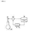
- Fig. 1 is a constructional view showing the flow of a fuel via a plunger type pump of the present invention.
- the plunger type pump 10 in the present invention has an escape valve 12 (its construction will be described later) therein.
- a fuel introduced from a fuel tank 96 to the plunger type pump 10 is discharged from an injector 98 to an engine 100 via a pressure regulator 102.
- the escape valve 12 performs the same operation as the pressure regulator 102 conventionally used.
- the pressure regulator 102 is shown, but can be omitted.
- Fig. 2 is a cross-sectional view showing one embodiment mode of the plunger type pump of the present invention.
- Fig. 3 is an exploded sectional view of a main portion of Fig. 2.
- a raw material of the pump body 14 is set to a resin material of a low coefficient of thermal conductivity such as phenol resin, etc.
- a longitudinal cylinder storing hole 16 and a cam chamber 18 communicated with a lower portion of this cylinder storing hole 16 are formed within this pump body 14.
- a first step difference 20 having a small diameter and located relatively downward and a second step difference 22 having a large diameter and located relatively upward are formed in an inner wall of the cylinder storing hole 16.
- a cylinder assembly 24 is inserted into the cylinder storing hole 16, and its insertion tip abuts on the first step difference 20.
- an upper end of the cylinder assembly 24 is located within the cylinder storing hole 16.
- An O-ring 26 coming in contact with the pump body 14 is arranged in an outer circumference of the cylinder assembly 24 in its position near the first step difference 20.
- the cylinder storing hole 16 and the cam chamber 18 are partitioned by this O-ring 26.
- the cylinder assembly 24 has a cylinder 28 having the above O-ring 26 on its outside face, and a plunger 30 slidably arranged within this cylinder 28 and formed in a sleeve shape in which one end of the plunger 30 is closed.
- An internal space of the sleeve shape of the plunger 30 is set to a fuel passage 32.
- An inlet valve 34 and a valve member 36 for the inlet valve, and an outlet valve 38 and a valve member 40 for the outlet valve are sequentially arranged upward within the cylinder 28 in positions communicated with an upper portion side opening portion of the fuel passage 32 of the plunger 30.
- Fig. 4 shows a plan view of the inlet valve 34 and the outlet valve 38.
- the valve member 40 is an opening portion closing member for closing an upper end of the cylinder 28.
- the valve member 40 is press-fitted to an opening portion of the cylinder 28.
- a fuel passage outlet 42 communicated with the fuel passage 32 of the plunger 30 is formed in this valve member 40.
- the cylinder assembly 24 further has a pin 44 and a spring 46.
- the pin 44 extends through the cylinder assembly 24 in a direction perpendicular to an axial direction of the cylinder 28 and the plunger 30.
- the spring 46 is arranged in the internal space (fuel passage 32) of the sleeve shape of the plunger 30. One end of the spring 46 comes in contact with the pin 44, and the other end comes in contact with a closing face of the plunger 30.
- the pin 44 is fixed to the cylinder 28, but is not fixed to the plunger 30.
- An elongated hole 48 is formed in the plunger 30 such that the plunger 30 can be freely moved in the axial direction in a predetermined range with respect to the pin 44.
- the pin 44 is inserted into this elongated hole 48. This elongated hole 48 communicates the interior and exterior of a sleeve-shaped portion of the plunger 30.
- the plunger 30, the pin 44, the spring 46, the inlet valve 34, the valve member 36 for the inlet valve, the outlet valve 38, the valve member 40 for the outlet valve, etc. are assembled into the cylinder 28.
- the cylinder assembly 24 can be set to an independent assembly body.
- the cylinder 28, the plunger 30, the valve member 40, etc. as main constructional members exposed to the exterior are constructed by metallic materials. Accordingly, when the fuel pressure within the fuel passage 32 becomes high, this high pressure fuel is stored into the cylinder assembly 24 so that no pump body 14 is directly influenced by this high pressure.
- the cylinder assembly 24 is mounted into the cylinder storing hole 16 of the pump body 14.
- a longitudinal clearance of a ring shape is formed between an inner wall of the cylinder storing hole 16 of the pump body 14 and an outer wall of the cylinder 28 on an upper side from a position slightly upward from a position of the O-ring 26.
- a longitudinal narrow width clearance 50 of a ring shape is formed near the cylinder 28 in a fixing position of the pin 44.
- a longitudinal wide width clearance 52 of a ring shape is formed near an upper end of the cylinder 28.
- a nipple 54 for introducing the fuel and communicated with a lower portion of the fuel tank 96 is attached to the pump body 14. This nipple 54 for introducing the fuel is communicated with the above narrow width clearance 50.
- a fuel introducing passage 58 for communicating the interior and exterior of the cylinder 28 is formed in the cylinder 28 near the fixing position of the pin 44.
- This fuel introducing passage 58 is set such that an outer side of the fuel introducing passage 58 is located near the nipple 54 for introducing the fuel, and an inner side of the fuel introducing passage 58 is located near the elongated hole 48 formed in the plunger 30.
- the fuel introduced from the nipple 54 for introducing the fuel is transmitted from the narrow width clearance 50 to the fuel passage 32 formed within the plunger 30 via the fuel introducing passage 58 of the cylinder 28 and the elongated hole 48 of the plunger 30.
- a tip of a driving shaft 60 directly connected to the unillustrated engine is inserted into the cam chamber 18, and a cam member 62 is attached to this tip of the driving shaft 60.
- An axial center of this cam member 62 and an axial center of the driving shaft 60 are offset.
- the center of rotation of the driving shaft 60 is set to P
- the center of rotation of the cam member 62 is set to Q.
- a lower end of the plunger 30 on its close end face comes in contact with an upper portion surface of this cam member 62 by the spring 46.
- the plunger 30 coming in contact with the cam member 62 is reciprocated upward and downward within the cylinder 28.
- the fuel introduced to the fuel passage 32 within the plunger 30 is discharged to the exterior via the fuel passage outlet 42 by operations of the inlet valve 34 and the outlet valve 48 by the upward and downward reciprocating movement of this plunger 30.
- the operations of the inlet valve 34 and the outlet valve 38 using the reciprocating movement of the plunger 30 are conventionally known in technique. Accordingly, an explanation of these operations is omitted here.
- the construction of the cylinder assembly 24 is not limited to the above construction if the plunger 30 is reciprocated by rotating the driving shaft 60 and the fuel is discharged to the exterior after the fuel is introduced into the cylinder assembly 24.
- a plug 64 is mounted into the wide width clearance 52 so as to cover an upper end of the above cylinder assembly 24.
- the plug 64 is constructed by a base portion 66 of a plate shape, a first sleeve-shaped portion 68 having a relatively large diameter, and a second sleeve-shaped portion 70 having a relatively small diameter.
- the first sleeve-shaped portion 68 is used to cover an outer side of the above cylinder 28 (is mounted into the above wide width clearance 52), and is formed integrally with a one-face side of the base portion 66.
- the second sleeve-shaped portion 70 is formed integrally with a face side opposed to this base portion 66.
- the plug 64 is desirably formed by resin of a low coefficient of thermal conductivity such as phenol resin, etc.
- a communication passage 72 extending through the base portion 66 is formed at a center of the base portion 66 of a plate shape. Namely, this communication passage 72 formed in the base portion 66 communicates an internal space of the first sleeve-shaped portion 68 and an internal space of the second sleeve-shaped portion 70.
- An O-ring 74 as a shield member is attached to a surface of the base portion 66 on its side of the first sleeve-shaped portion 68 so as to surround the communication passage 72.
- a flange 76 is formed outside the first sleeve-shaped portion 68 near its free tip.
- An O-ring 78 is attached to an outer face of this flange 76.
- a spring 80 is arranged outside the first sleeve-shaped portion 68 such that one end of the spring 80 comes in contact with a shoulder of the flange 76. This spring 80 is used to bias the plug 64 on a downward side in Fig. 2.
- the above escape valve 12 is constructed by the spring 80 for biasing the plug 64 in a predetermined direction, the plug 64 movable in the axial direction, and the O-ring 74 attached to the plug 64 or the cylinder assembly 24.
- a fuel escape passage 79 is formed between an inner wall of the first sleeve-shaped portion 68 of the plug 64 and an outer wall of the cylinder 28.
- the fuel escape passage 79 is formed in the exterior of the cylinder 28, and is communicated with the fuel passage 32. However, this communication is open-interrupted by the O-ring 74.
- this fuel escape passage 79 is communicated with a communication portion of the fuel passage outlet 42 of the valve member 40 for the outlet valve and the communication passage 72 of the plug 64.
- the other side of the fuel escape passage 79 is communicated with the narrow width clearance 50.
- the fuel escape passage 79 is communicated with an inlet side of the fuel passage 28 through the narrow width clearance 50, the fuel introducing passage 58 of the cylinder 28 and the elongated hole 48 of the plunger 30.
- the shape of an outer wall of the second sleeve-shaped portion 70 seen from a plane is set to an oval shape or an elliptical shape having parallel lines on both sides of this second sleeve-shaped portion 70.
- a plate 82 having a hole 81 fitted to the second sleeve-shaped portion 70 is fitted to the second sleeve-shaped portion 70.
- This plate 82 comes in contact with an upper face of the pump body 14, and is fixed to the pump body 14 by using a screw 84.
- the plug 64 is attached to the pump body 14 (plate 82) in an unrotating state.
- the fixing state of the plate 82 to the pump body 14 is set to a normal state (shown in Figs. 2 and 3).
- a normal state the spring 80 arranged outside the first sleeve-shaped portion 68 is compressed by a shoulder portion of the flange 76 and a bottom face of the plate 82, and a downward biasing force is applied to the plug 64 by the spring 80 in Fig. 2.
- the O-ring 74 attached to the base portion 66 of the plug 64 comes in contact with an upper face of the cylinder assembly 24 by this biasing force of this spring 80 to the plug 64 (in Fig. 2, the O-ring 74 comes in contact with the valve member 40, but may also come in contact with the cylinder 28).
- a clearance C is set to be located between an upper face 67 (a position outside the second sleeve-shaped portion 70) of the base portion 66 of the plug 64 and a lower face of the plate 82.
- the plug 64 is movably arranged upward by a distance of the clearance C in Figs. 2 and 3.
- the O-ring 74 attached to the base portion 66 is set such that no O-ring 74 comes in contact with the upper face of the cylinder assembly 24 (valve member 40).
- a female screw portion 86 is formed in the inner wall of the second sleeve-shaped portion 70 of the plug 64.
- a male screw portion 90 is formed in the outer wall of a discharge connector 88. This male screw portion 90 of the discharge connector 88 is screwed into the female screw portion 86 of the second sleeve-shaped portion 70.
- a packing 91 is nipped when this discharge connector 88 is screwed into the second sleeve-shaped portion 70.
- a discharge passage 92 is formed in the discharge connector 88. One side of this discharge passage 92 is communicated with the communication passage 72 of the plug 64, and the other side is communicated with the injector 98 (Fig. 1).
- one portion of the fuel discharged from the fuel passage outlet 42 of the valve member 40 passes between an inner wall face of the first sleeve-shaped portion 68 of the plug 64 and an outer face of the cylinder assembly 24, and reaches the narrow width clearance 50 from the fuel escape passage 79.
- the fuel reaching this narrow width clearance 50 is again returned from an inlet of the fuel passage 32 into the fuel passage 32 via the fuel introducing passage 58 of the cylinder 28 and the elongated hole 48 of the plunger 30.
- the fuel pressure within the plunger type pump 10 when the fuel pressure within the plunger type pump 10 is increased, one portion of the fuel discharged from the fuel passage 32 to the discharge passage 92 is escaped to the fuel escape passage 79 within the plunger type pump 10 so that no fuel pressure of the fuel passage 32 becomes a high pressure equal to or higher than the predetermined pressure.
- the fuel escaped from the fuel escape passage 79 to the narrow width space 50 comes in contact with the pump body 14, but the fuel pressure in this contact position is reduced. Accordingly, no unbearable problem in strength is caused even when the pump body 14 is formed by a resin material.
- the plug 64 is fitted to the plate 82 in an unrotating state, and is pressed against a valve case 16 by the spring 80 and is fixed to this valve case 16. Since there is thus no screw fastening of the plug 64 to the pump body 14, the discharge connector 88 is easily mounted to the plug 64.
- the O-ring 74 as a shield member is attached to the plug 64.
- the O-ring 74 may be also attached to the cylinder assembly 24 (the valve member 40 or the cylinder 28).
- the elongated direction is set to a longitudinal direction, but may be also set to a transversal direction.
- the fuel entering the fuel escape passage 79 is again returned to the fuel passage 32.
- the fuel entering the fuel escape passage 79 may be also returned to the fuel tank 96 by communicating the fuel escape passage 79 with a passage for returning the fuel from the pressure regulator 102 to the fuel tank 96.
- the plunger type pump in the present invention when the internal fuel pressure becomes a high pressure, a shielded portion is opened by moving the plug and the high pressure fuel is automatically discharged from the fuel passage to the fuel escape passage. Accordingly, no internal pressure of the plunger type pump becomes a high pressure equal to or higher than a predetermined pressure so that durability of the plunger type pump can be improved.
- a raw material of the pump body can be constructed by a resin material of a low coefficient of thermal conductivity instead of a metal as in the conventional case.
- the pump body can be made light in weight and its cost can be reduced.
- vapor countermeasure can be improved by restraining a rise in fuel temperature of the pump body.
- an escape valve for escaping the high pressure fuel to the exterior is constructed by the movable plug and the shield member. Accordingly, it is also possible to omit the pressure regulator conventionally required.
- the plug is fixed to the pump body without screw fastening in an unrotatable state.
- the plunger type pump is easily assembled, and no plug is excessively fastened at a fastening time of a connector to the plug. Further, no plug is unfastened at a detaching time of the connector. Accordingly, fuel leakage due to the high pressure can be improved.
- the cylinder assembly can be assembled as an integral object in a separate process from the pump body so that a pump body assembly work of the cylinder assembly is easily made.
Landscapes
- Engineering & Computer Science (AREA)
- Mechanical Engineering (AREA)
- General Engineering & Computer Science (AREA)
- Fuel-Injection Apparatus (AREA)
- Details Of Reciprocating Pumps (AREA)
- Reciprocating Pumps (AREA)
Abstract
Description
- The present invention relates to a plunger type pump, and particularly relates to the plunger type pump in which a pump body can be made by a resin material.
- The plunger type pump is conventionally known as a fuel pump used in a two wheeler, etc. In the plunger type pump, a cylinder storing hole is formed within the pump body (housing), and a cylinder is arranged within this cylinder storing hole. A plunger, an inlet valve and an outlet valve forming a fuel passage are arranged within this cylinder. A cam member is further arranged within the pump body (housing), and is rotated in association with the rotation of an engine and comes in contact with the above cylinder at any time. The plunger is slid within the cylinder by rotating this cam member, and a fuel introduced from a fuel tank is discharged to the engine.
- The cylinder storing hole formed within the pump body is closed by a plug. An insertion tip of this plug comes in contact with an insertion rear end of the cylinder (or a member fixed to the cylinder), and the cylinder is fixedly arranged in a predetermined position within the pump body. In a method for blocking the cylinder storing hole of the pump body by the plug, the plug is inserted into the cylinder storing hole of the pump body, and the plug is fixed to the pump body by caulking the insertion rear end of the plug so as to cover this insertion rear end with the pump body itself as shown in Japanese Laid-Open (Kokai) Patent Nos. 10-30575 and 10-30576.
- In another method for fixing the plug to the pump body, a female screw portion is formed in the inner wall of an opening portion of the cylinder storing hole of the pump body, and a male screw portion is formed in an outer wall of the plug. The plug is fixed to the pump body by screwing the male screw portion of the plug into the female screw portion of the cylinder storing hole.
- In the method for caulking the plug by the pump body, a metallic material must be used for the caulking in a raw material of the pump body.
- In the method for screwing the plug into the pump body, there is a case in which a fuel passage extending through the interior of the plug is formed in the plug, and the female screw portion is formed in an opening portion of this fuel passage, and an outlet connector forming the male screw portion in the outer wall is screwed into the female screw portion of the plug, and the fuel is discharged from this outlet connector. The plug is generally formed by resin in view of light weight and cost. In this case, when the outlet connector is screwed into the plug and is detached from the plug, there are defects in that the plug is excessively fastened to the pump body and unfastening of the plug from the pump body is caused. Further, there is a defect of generation of pressure leakage due to insufficiency of strength of the plug.
- In each of the conventional fixing methods, the metallic material must be used in the pump body to fix the plug to the pump body. In contrast to this, if the raw material of the pump body is formed by resin, it is considered that the pump can be made light in weight and its cost can be reduced and the generation of vapor can be prevented. However, there is a case in which an internal fuel pressure is abnormally increased in the plunger type pump. Accordingly, a problem exists in that no pump body made of resin can bear the internal fuel pressure in strength. Hence, no pump body made of resin can be adopted. Therefore, the metallic material must be conventionally used in the pump body so as to bear the high pressure so that no pump body can be made light in weight, and no cost can be reduced and no vapor generation can be prevented.
- As shown in Fig. 7, a fuel is introduced from a
fuel tank 96 to aplunger type pump 94, and is discharged from aninjector 98 to anengine 100. In the conventionalplunger type pump 94, when the fuel pressure within theplunger type pump 94 is high, apressure regulator 102 for returning this high pressure fuel to thefuel tank 96 is arranged in an intermediate portion communicated with theplunger type pump 94 and theinjector 98. Cost can be reduced if thispressure regulator 102 can be omitted. - In consideration of the above problem points, an object of the present invention is to provide a plunger type pump in which the pump can be made light in weight and cost can be reduced by making a pump body of resin, and no fuel pressure within the pump body is abnormally increased so that fuel leakage is prevented.
- The object of the present invention can be achieved by the features defined in the claims. Particularly,
to achieve the above object, the present invention resides in a plunger type pump comprising a cylinder storing hole formed within a pump body; a cylinder stored into this cylinder storing hole; a plunger able to be reciprocated within this cylinder and forming a fuel passage within the plunger; an inlet valve and an outlet valve for opening and closing said fuel passage; a plug attached to said pump body to close said cylinder storing hole; and a cam member arranged within said pump body and rotated by a driving shaft; wherein said plunger is reciprocated and the fuel within said fuel passage is moved by rotating this cam member; said plunger type pump being characterized in that said plug can be moved with respect to said cylinder; a spring for biasing said plug in a predetermined direction is arranged within said pump body; a communication passage communicated with said fuel passage is arranged in said plug; a fuel escape passage communicated with a communication position of said fuel passage and said communication passage is arranged; shield means is arranged in said cylinder or its opening portion closing member located in said plug or a position opposed to the plug; said shield means comes in contact with said cylinder, its opening portion closing member or said plug by said spring, and no leakage of the fuel from the communication position of said fuel passage and said communication passage to said fuel escape passage is caused by said shield means when the fuel pressure within said pump body is equal to lower than a predetermined pressure; and no shield means comes in contact with said cylinder, its opening portion closing member or said plug by the fuel pressure against biasing force of said spring, and one portion of the fuel of said fuel passage is leaked to said fuel escape passage by communicating said fuel escape passage and the communication position of said fuel passage and said communication passage when the fuel pressure within said pump body is equal to or higher than the predetermined pressure. - The invention is described in more detail in connection with the drawings, in which;
- Fig. 1 is a constructional view showing the flow of a fuel via a plunger type pump of the present invention,
- Fig. 2 is a cross-sectional view showing one embodiment mode of the plunger type pump in the present invention,
- Fig. 3 is an exploded sectional view of a main portion of Fig. 2,
- Fig. 4 is a plan view of an inlet valve and an outlet valve used in the plunger type pump in the present invention,
- Fig. 5 is a plan view seen from an A-direction of Fig. 3.
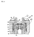
- Fig. 6 is a cross-sectional view of a main portion showing a state in which a plug is moved upward from a state of Fig. 2, and
- Fig. 7 is a constructional view showing the flow of a fuel via a conventional plunger type pump.
-
- Fig. 1 is a constructional view showing the flow of a fuel via a plunger type pump of the present invention. The
plunger type pump 10 in the present invention has an escape valve 12 (its construction will be described later) therein. A fuel introduced from afuel tank 96 to theplunger type pump 10 is discharged from aninjector 98 to anengine 100 via apressure regulator 102. In the present invention, when a fuel pressure is increased within theplunger type pump 10, the fuel is escaped by theescape valve 12 to another portion within theplunger type pump 10 so that the fuel pressure is reduced. Theescape valve 12 performs the same operation as thepressure regulator 102 conventionally used. In Fig. 1, thepressure regulator 102 is shown, but can be omitted. - Fig. 2 is a cross-sectional view showing one embodiment mode of the plunger type pump of the present invention. Fig. 3 is an exploded sectional view of a main portion of Fig. 2. A raw material of the
pump body 14 is set to a resin material of a low coefficient of thermal conductivity such as phenol resin, etc. A longitudinalcylinder storing hole 16 and acam chamber 18 communicated with a lower portion of thiscylinder storing hole 16 are formed within thispump body 14. Afirst step difference 20 having a small diameter and located relatively downward and a second step difference 22 having a large diameter and located relatively upward are formed in an inner wall of thecylinder storing hole 16. Acylinder assembly 24 is inserted into thecylinder storing hole 16, and its insertion tip abuts on thefirst step difference 20. In a mounting state of thecylinder assembly 24 into thecylinder storing hole 16, an upper end of thecylinder assembly 24 is located within thecylinder storing hole 16. An O-ring 26 coming in contact with thepump body 14 is arranged in an outer circumference of thecylinder assembly 24 in its position near thefirst step difference 20. Thecylinder storing hole 16 and thecam chamber 18 are partitioned by this O-ring 26. - The
cylinder assembly 24 has acylinder 28 having the above O-ring 26 on its outside face, and aplunger 30 slidably arranged within thiscylinder 28 and formed in a sleeve shape in which one end of theplunger 30 is closed. An internal space of the sleeve shape of theplunger 30 is set to afuel passage 32. Aninlet valve 34 and avalve member 36 for the inlet valve, and anoutlet valve 38 and avalve member 40 for the outlet valve are sequentially arranged upward within thecylinder 28 in positions communicated with an upper portion side opening portion of thefuel passage 32 of theplunger 30. Fig. 4 shows a plan view of theinlet valve 34 and theoutlet valve 38. Thevalve member 40 is an opening portion closing member for closing an upper end of thecylinder 28. For example, thevalve member 40 is press-fitted to an opening portion of thecylinder 28. Afuel passage outlet 42 communicated with thefuel passage 32 of theplunger 30 is formed in thisvalve member 40. - The
cylinder assembly 24 further has apin 44 and aspring 46. Thepin 44 extends through thecylinder assembly 24 in a direction perpendicular to an axial direction of thecylinder 28 and theplunger 30. Thespring 46 is arranged in the internal space (fuel passage 32) of the sleeve shape of theplunger 30. One end of thespring 46 comes in contact with thepin 44, and the other end comes in contact with a closing face of theplunger 30. Thepin 44 is fixed to thecylinder 28, but is not fixed to theplunger 30. Anelongated hole 48 is formed in theplunger 30 such that theplunger 30 can be freely moved in the axial direction in a predetermined range with respect to thepin 44. Thepin 44 is inserted into thiselongated hole 48. Thiselongated hole 48 communicates the interior and exterior of a sleeve-shaped portion of theplunger 30. - In the
cylinder assembly 24, theplunger 30, thepin 44, thespring 46, theinlet valve 34, thevalve member 36 for the inlet valve, theoutlet valve 38, thevalve member 40 for the outlet valve, etc. are assembled into thecylinder 28. Thus, thecylinder assembly 24 can be set to an independent assembly body. In thiscylinder assembly 24, thecylinder 28, theplunger 30, thevalve member 40, etc. as main constructional members exposed to the exterior are constructed by metallic materials. Accordingly, when the fuel pressure within thefuel passage 32 becomes high, this high pressure fuel is stored into thecylinder assembly 24 so that nopump body 14 is directly influenced by this high pressure. - The
cylinder assembly 24 is mounted into thecylinder storing hole 16 of thepump body 14. In a mounting state of thecylinder assembly 24 into thecylinder storing hole 16, a longitudinal clearance of a ring shape is formed between an inner wall of thecylinder storing hole 16 of thepump body 14 and an outer wall of thecylinder 28 on an upper side from a position slightly upward from a position of the O-ring 26. A longitudinalnarrow width clearance 50 of a ring shape is formed near thecylinder 28 in a fixing position of thepin 44. A longitudinalwide width clearance 52 of a ring shape is formed near an upper end of thecylinder 28. Anipple 54 for introducing the fuel and communicated with a lower portion of thefuel tank 96 is attached to thepump body 14. Thisnipple 54 for introducing the fuel is communicated with the abovenarrow width clearance 50. - A
fuel introducing passage 58 for communicating the interior and exterior of thecylinder 28 is formed in thecylinder 28 near the fixing position of thepin 44. Thisfuel introducing passage 58 is set such that an outer side of thefuel introducing passage 58 is located near thenipple 54 for introducing the fuel, and an inner side of thefuel introducing passage 58 is located near theelongated hole 48 formed in theplunger 30. Namely, the fuel introduced from thenipple 54 for introducing the fuel is transmitted from thenarrow width clearance 50 to thefuel passage 32 formed within theplunger 30 via thefuel introducing passage 58 of thecylinder 28 and theelongated hole 48 of theplunger 30. - A tip of a driving
shaft 60 directly connected to the unillustrated engine is inserted into thecam chamber 18, and acam member 62 is attached to this tip of the drivingshaft 60. An axial center of thiscam member 62 and an axial center of the drivingshaft 60 are offset. In Fig. 2, the center of rotation of the drivingshaft 60 is set to P, and the center of rotation of thecam member 62 is set to Q. A lower end of theplunger 30 on its close end face comes in contact with an upper portion surface of thiscam member 62 by thespring 46. - When the driving
shaft 60 is rotated, theplunger 30 coming in contact with thecam member 62 is reciprocated upward and downward within thecylinder 28. The fuel introduced to thefuel passage 32 within theplunger 30 is discharged to the exterior via thefuel passage outlet 42 by operations of theinlet valve 34 and theoutlet valve 48 by the upward and downward reciprocating movement of thisplunger 30. The operations of theinlet valve 34 and theoutlet valve 38 using the reciprocating movement of theplunger 30 are conventionally known in technique. Accordingly, an explanation of these operations is omitted here. - The construction of the
cylinder assembly 24 is not limited to the above construction if theplunger 30 is reciprocated by rotating the drivingshaft 60 and the fuel is discharged to the exterior after the fuel is introduced into thecylinder assembly 24. - A
plug 64 is mounted into thewide width clearance 52 so as to cover an upper end of theabove cylinder assembly 24. Theplug 64 is constructed by abase portion 66 of a plate shape, a first sleeve-shapedportion 68 having a relatively large diameter, and a second sleeve-shapedportion 70 having a relatively small diameter. The first sleeve-shapedportion 68 is used to cover an outer side of the above cylinder 28 (is mounted into the above wide width clearance 52), and is formed integrally with a one-face side of thebase portion 66. The second sleeve-shapedportion 70 is formed integrally with a face side opposed to thisbase portion 66. Theplug 64 is desirably formed by resin of a low coefficient of thermal conductivity such as phenol resin, etc. Acommunication passage 72 extending through thebase portion 66 is formed at a center of thebase portion 66 of a plate shape. Namely, thiscommunication passage 72 formed in thebase portion 66 communicates an internal space of the first sleeve-shapedportion 68 and an internal space of the second sleeve-shapedportion 70. An O-ring 74 as a shield member is attached to a surface of thebase portion 66 on its side of the first sleeve-shapedportion 68 so as to surround thecommunication passage 72. - A
flange 76 is formed outside the first sleeve-shapedportion 68 near its free tip. An O-ring 78 is attached to an outer face of thisflange 76. Aspring 80 is arranged outside the first sleeve-shapedportion 68 such that one end of thespring 80 comes in contact with a shoulder of theflange 76. Thisspring 80 is used to bias theplug 64 on a downward side in Fig. 2. Theabove escape valve 12 is constructed by thespring 80 for biasing theplug 64 in a predetermined direction, theplug 64 movable in the axial direction, and the O-ring 74 attached to theplug 64 or thecylinder assembly 24. - In a mounting state of the first sleeve-shaped
portion 68 of theplug 64 into the wide width clearance 52 (in Figs. 2 and 3), the O-ring 78 comes in contact with an inner wall of thecylinder storing hole 16, and the fuel leakage between the inner wall of thecylinder storing hole 16 of thepump body 14 and an outer wall of theplug 64 is prevented by the O-ring 78. In the mounting state of the first sleeve-shapedportion 68 of theplug 64 into the wide width clearance 52 (in Figs. 2 and 3), afuel escape passage 79 is formed between an inner wall of the first sleeve-shapedportion 68 of theplug 64 and an outer wall of thecylinder 28. Thefuel escape passage 79 is formed in the exterior of thecylinder 28, and is communicated with thefuel passage 32. However, this communication is open-interrupted by the O-ring 74. - One side of this
fuel escape passage 79 is communicated with a communication portion of thefuel passage outlet 42 of thevalve member 40 for the outlet valve and thecommunication passage 72 of theplug 64. The other side of thefuel escape passage 79 is communicated with thenarrow width clearance 50. Thefuel escape passage 79 is communicated with an inlet side of thefuel passage 28 through thenarrow width clearance 50, thefuel introducing passage 58 of thecylinder 28 and theelongated hole 48 of theplunger 30. - As shown in Fig. 5, the shape of an outer wall of the second sleeve-shaped
portion 70 seen from a plane is set to an oval shape or an elliptical shape having parallel lines on both sides of this second sleeve-shapedportion 70. Aplate 82 having ahole 81 fitted to the second sleeve-shapedportion 70 is fitted to the second sleeve-shapedportion 70. Thisplate 82 comes in contact with an upper face of thepump body 14, and is fixed to thepump body 14 by using ascrew 84. In a fixing state of theplate 82 to thepump body 14, theplug 64 is attached to the pump body 14 (plate 82) in an unrotating state. - The fixing state of the
plate 82 to thepump body 14 is set to a normal state (shown in Figs. 2 and 3). In this normal state, thespring 80 arranged outside the first sleeve-shapedportion 68 is compressed by a shoulder portion of theflange 76 and a bottom face of theplate 82, and a downward biasing force is applied to theplug 64 by thespring 80 in Fig. 2. The O-ring 74 attached to thebase portion 66 of theplug 64 comes in contact with an upper face of thecylinder assembly 24 by this biasing force of thisspring 80 to the plug 64 (in Fig. 2, the O-ring 74 comes in contact with thevalve member 40, but may also come in contact with the cylinder 28). Thus, leakage of the fuel from a communication portion of the abovefuel passage outlet 42 and theabove communication passage 72 to the abovefuel escape passage 79 is prevented by the O-ring 74. In this normal state, a clearance C is set to be located between an upper face 67 (a position outside the second sleeve-shaped portion 70) of thebase portion 66 of theplug 64 and a lower face of theplate 82. Theplug 64 is movably arranged upward by a distance of the clearance C in Figs. 2 and 3. - When the
plug 64 is moved upward by the distance of the clearance C from the state of each of Figs. 2 and 3 and the upper face of thebase portion 66 and the lower face of theplate 82 come in contact with each other, the O-ring 74 attached to thebase portion 66 is set such that no O-ring 74 comes in contact with the upper face of the cylinder assembly 24 (valve member 40). - A
female screw portion 86 is formed in the inner wall of the second sleeve-shapedportion 70 of theplug 64. Amale screw portion 90 is formed in the outer wall of adischarge connector 88. Thismale screw portion 90 of thedischarge connector 88 is screwed into thefemale screw portion 86 of the second sleeve-shapedportion 70. A packing 91 is nipped when thisdischarge connector 88 is screwed into the second sleeve-shapedportion 70. Adischarge passage 92 is formed in thedischarge connector 88. One side of thisdischarge passage 92 is communicated with thecommunication passage 72 of theplug 64, and the other side is communicated with the injector 98 (Fig. 1). - In the
plunger type pump 10 constructed above, when the pressure of thefuel passage 32 within theplunger 30 is a pressure within a predetermined value, the O-ring 74 comes in contact with the upper face (valve member 40) of thecylinder assembly 24 as shown in Figs. 2 and 3. The fuel within thefuel passage 32 of theplunger 30 is discharged from thefuel passage outlet 42 of thevalve member 40 to thedischarge passage 92 of thedischarge connector 88 via thecommunication passage 72 of theplug 64. In this case, no fuel is leaked by the O-ring 74 from the communication portion of thefuel passage outlet 42 and thecommunication passage 72 to thefuel escape passage 79. - When the fuel pressure within the
fuel passage 32 of theplunger 30 reaches a high pressure equal to or higher than a predetermined pressure, this high pressure fuel enters between the upper face of thecylinder assembly 24, theplug 64 and the bottom face of thebase portion 66, and moves theplug 64 upward in Figs. 2 and 3 against the biasing force of thespring 46. Thus, theupper face 67 of thebase portion 66 of theplug 64 comes in contact with the lower face of the plate 82 (Fig. 6). In this state of Fig. 6, no O-ring 74 attached to a lower side of thebase portion 66 comes in contact with the upper face of the cylinder assembly 24 (valve member 40). Thus, the shield between the upper face of the cylinder assembly 24 (valve member 40) and a lower face of thebase portion 66 of theplug 64 is dissolved. - As a result, one portion of the fuel discharged from the
fuel passage outlet 42 of thevalve member 40 passes between an inner wall face of the first sleeve-shapedportion 68 of theplug 64 and an outer face of thecylinder assembly 24, and reaches thenarrow width clearance 50 from thefuel escape passage 79. The fuel reaching thisnarrow width clearance 50 is again returned from an inlet of thefuel passage 32 into thefuel passage 32 via thefuel introducing passage 58 of thecylinder 28 and theelongated hole 48 of theplunger 30. Namely, in the present invention, when the fuel pressure within theplunger type pump 10 is increased, one portion of the fuel discharged from thefuel passage 32 to thedischarge passage 92 is escaped to thefuel escape passage 79 within theplunger type pump 10 so that no fuel pressure of thefuel passage 32 becomes a high pressure equal to or higher than the predetermined pressure. In this case, the fuel escaped from thefuel escape passage 79 to thenarrow width space 50 comes in contact with thepump body 14, but the fuel pressure in this contact position is reduced. Accordingly, no unbearable problem in strength is caused even when thepump body 14 is formed by a resin material. - In the present invention, the
plug 64 is fitted to theplate 82 in an unrotating state, and is pressed against avalve case 16 by thespring 80 and is fixed to thisvalve case 16. Since there is thus no screw fastening of theplug 64 to thepump body 14, thedischarge connector 88 is easily mounted to theplug 64. - In the drawings and the above explanation, the O-
ring 74 as a shield member is attached to theplug 64. However, instead of this, the O-ring 74 may be also attached to the cylinder assembly 24 (thevalve member 40 or the cylinder 28). - In the above explanation of the
plunger type pump 10, the elongated direction is set to a longitudinal direction, but may be also set to a transversal direction. - Further, in the above explanation, the fuel entering the
fuel escape passage 79 is again returned to thefuel passage 32. However, the fuel entering thefuel escape passage 79 may be also returned to thefuel tank 96 by communicating thefuel escape passage 79 with a passage for returning the fuel from thepressure regulator 102 to thefuel tank 96. - As mentioned above, in accordance with the plunger type pump in the present invention, when the internal fuel pressure becomes a high pressure, a shielded portion is opened by moving the plug and the high pressure fuel is automatically discharged from the fuel passage to the fuel escape passage. Accordingly, no internal pressure of the plunger type pump becomes a high pressure equal to or higher than a predetermined pressure so that durability of the plunger type pump can be improved.
- In the present invention, it is possible to prevent the internal pressure of the plunger type pump from becoming a high pressure. Accordingly, a raw material of the pump body can be constructed by a resin material of a low coefficient of thermal conductivity instead of a metal as in the conventional case. As a result, the pump body can be made light in weight and its cost can be reduced. Further, vapor countermeasure can be improved by restraining a rise in fuel temperature of the pump body.
- In the plunger type pump in the present invention, an escape valve for escaping the high pressure fuel to the exterior is constructed by the movable plug and the shield member. Accordingly, it is also possible to omit the pressure regulator conventionally required.
- In the present invention, the plug is fixed to the pump body without screw fastening in an unrotatable state. As a result, the plunger type pump is easily assembled, and no plug is excessively fastened at a fastening time of a connector to the plug. Further, no plug is unfastened at a detaching time of the connector. Accordingly, fuel leakage due to the high pressure can be improved.
- Further, in the present invention, the cylinder assembly can be assembled as an integral object in a separate process from the pump body so that a pump body assembly work of the cylinder assembly is easily made.
Claims (7)
- A plunger type pump comprising a cylinder storing hole (16) formed within a pump body (14); a cylinder (28) stored into this cylinder storing hole; a plunger (30) able to be reciprocated within this cylinder and forming a fuel passage (32) within the plunger; an inlet valve (34) and an outlet valve (38) for opening and closing said fuel passage; a plug attached to said pump body to close said cylinder storing hole; and a cam member (62) arranged within said pump body and rotated by a driving shaft (60); wherein said plunger is reciprocated and the fuel within said fuel passage is moved by rotating this cam member; said plunger type pump being characterized in that said plug can be moved with respect to said cylinder; a spring (80) for biasing said plug in a predetermined direction is arranged within said pump body; a communication passage (72) communicated with said fuel passage is arranged in said plug; a fuel escape passage (79) communicated with a communication position of said fuel passage and said communication passage is arranged; shield means (74) is arranged in said cylinder or its opening portion closing member located in said plug or a position opposed to the plug; said shield means comes in contact with said cylinder, its opening portion closing member or said plug by said spring, and no leakage of the fuel from the communication position of said fuel passage and said communication passage to said fuel escape passage is caused by said shield means when the fuel pressure within said pump body is equal to lower than a predetermined pressure; and no shield means comes in contact with said cylinder, its opening portion closing member or said plug by the fuel pressure against biasing force of said spring, and one portion of the fuel of said fuel passage is leaked to said fuel escape passage by communicating said fuel escape passage and the communication position of said fuel passage and said communication passage when the fuel pressure within said pump body is equal to or higher than the predetermined pressure.
- The plunger type pump as defined in claim 1, wherein said fuel escape passage is communicated with an inlet side of said fuel passage.
- The plunger type pump as defined in claim 1 or 2, wherein a raw material of said pump body is resin.
- The plunger type pump as defined in any one of claims 1 to 3, wherein said plug is constructed by a base portion (66) forming said communication passage and having said shield member arranged around this communication passage, a first sleeve-shaped portion (68) arranged on a shield member side of this base portion and covering an outer side of said cylinder, and a second sleeve-shaped portion (70) arranged on a side opposed to the first sleeve-shaped portion in the base portion, and a discharge connector having a discharge passage communicated with said communication passage is fixed to the second sleeve-shaped portion.
- The plunger type pump as defined in any one of claims 1 to 4, wherein no plug can be rotated with respect to the pump body.
- The plunger type pump as defined in any one of claims 1 to 5, wherein a cylinder assembly is formed by arranging said plunger, said inlet valve, said outlet valve and said opening portion closing member in said cylinder, and is assembled into said pump body.
- The plunger type pump as defined in claim 6, wherein a main member constituting an outer wall of said cylinder assembly is constructed by a metal.
Applications Claiming Priority (2)
| Application Number | Priority Date | Filing Date | Title |
|---|---|---|---|
| JP33391999A JP2001153033A (en) | 1999-11-25 | 1999-11-25 | Plunger pump |
| JP33391999 | 1999-11-25 |
Publications (4)
| Publication Number | Publication Date |
|---|---|
| EP1103722A2 true EP1103722A2 (en) | 2001-05-30 |
| EP1103722A3 EP1103722A3 (en) | 2003-02-05 |
| EP1103722B1 EP1103722B1 (en) | 2006-05-10 |
| EP1103722B8 EP1103722B8 (en) | 2006-12-13 |
Family
ID=18271444
Family Applications (1)
| Application Number | Title | Priority Date | Filing Date |
|---|---|---|---|
| EP20000125242 Expired - Lifetime EP1103722B8 (en) | 1999-11-25 | 2000-11-23 | Plunger type pump |
Country Status (3)
| Country | Link |
|---|---|
| EP (1) | EP1103722B8 (en) |
| JP (1) | JP2001153033A (en) |
| DE (1) | DE60027841D1 (en) |
Cited By (17)
| Publication number | Priority date | Publication date | Assignee | Title |
|---|---|---|---|---|
| DE102008013473A1 (en) * | 2008-03-10 | 2009-09-17 | Wilo Ag | Pump housing with rotatable mounting flanges |
| DE10361573B4 (en) * | 2003-12-23 | 2012-08-16 | Robert Bosch Gmbh | Pumping device, in particular high-pressure fuel pump |
| US10947967B1 (en) | 2020-03-11 | 2021-03-16 | Halliburton Energy Services, Inc. | Discharge valve disabler and pressure pulse generator therefrom |
| US10989188B2 (en) | 2019-07-26 | 2021-04-27 | Halliburton Energy Services, Inc. | Oil field pumps with reduced maintenance |
| US11002120B1 (en) | 2020-02-28 | 2021-05-11 | Halliburton Energy Services, Inc. | Dynamic packing seal compression system for pumps |
| US11073144B1 (en) | 2020-02-14 | 2021-07-27 | Halliburton Energy Services, Inc. | Pump valve assembly |
| US11105327B2 (en) | 2019-05-14 | 2021-08-31 | Halliburton Energy Services, Inc. | Valve assembly for a fluid end with limited access |
| US11231111B2 (en) | 2019-05-14 | 2022-01-25 | Halliburton Energy Services, Inc. | Pump valve seat with supplemental retention |
| US11261863B2 (en) | 2019-05-14 | 2022-03-01 | Halliburton Energy Services, Inc. | Flexible manifold for reciprocating pump |
| US11280326B2 (en) | 2019-06-10 | 2022-03-22 | Halliburton Energy Services, Inc. | Pump fluid end with suction valve closure assist |
| US11441687B2 (en) | 2019-05-14 | 2022-09-13 | Halliburton Energy Services, Inc. | Pump fluid end with positional indifference for maintenance |
| US11530750B2 (en) | 2019-12-24 | 2022-12-20 | Halliburton Energy Services, Inc. | Horizontal balanced guided valve |
| US11560888B2 (en) | 2019-05-14 | 2023-01-24 | Halliburton Energy Services, Inc. | Easy change pump plunger |
| US11739748B2 (en) | 2019-05-14 | 2023-08-29 | Halliburton Energy Services, Inc. | Pump fluid end with easy access suction valve |
| US11952986B2 (en) | 2019-05-02 | 2024-04-09 | Kerr Machine Co. | Fracturing pump arrangement using a plunger with an internal fluid passage |
| US11965503B2 (en) | 2019-05-14 | 2024-04-23 | Halliburton Energy Services, Inc. | Flexible manifold for reciprocating pump |
| US12404942B2 (en) | 2020-02-14 | 2025-09-02 | Halliburton Energy Services, Inc. | Plunger or piston with hardened insert |
Families Citing this family (2)
| Publication number | Priority date | Publication date | Assignee | Title |
|---|---|---|---|---|
| JP5178676B2 (en) * | 2009-09-29 | 2013-04-10 | 日立オートモティブシステムズ株式会社 | High pressure fuel supply pump |
| JP7151457B2 (en) * | 2018-12-20 | 2022-10-12 | 株式会社Ihi | Piston pump, boost liquid supply system and liquid injection device |
Citations (2)
| Publication number | Priority date | Publication date | Assignee | Title |
|---|---|---|---|---|
| JPH1030576A (en) | 1996-07-18 | 1998-02-03 | Unisia Jecs Corp | Plunger pump |
| JPH1030575A (en) | 1996-07-18 | 1998-02-03 | Unisia Jecs Corp | Plunger pump |
Family Cites Families (3)
| Publication number | Priority date | Publication date | Assignee | Title |
|---|---|---|---|---|
| US2731917A (en) * | 1956-01-24 | evans | ||
| US4737086A (en) * | 1986-05-27 | 1988-04-12 | Diesel Kiki Co., Ltd. | Fuel injection pump having variable prestroke mechanism |
| DE19800500A1 (en) * | 1998-01-09 | 1999-07-15 | Bosch Gmbh Robert | Piston pump |
-
1999
- 1999-11-25 JP JP33391999A patent/JP2001153033A/en active Pending
-
2000
- 2000-11-23 EP EP20000125242 patent/EP1103722B8/en not_active Expired - Lifetime
- 2000-11-23 DE DE60027841T patent/DE60027841D1/en not_active Expired - Lifetime
Patent Citations (2)
| Publication number | Priority date | Publication date | Assignee | Title |
|---|---|---|---|---|
| JPH1030576A (en) | 1996-07-18 | 1998-02-03 | Unisia Jecs Corp | Plunger pump |
| JPH1030575A (en) | 1996-07-18 | 1998-02-03 | Unisia Jecs Corp | Plunger pump |
Cited By (20)
| Publication number | Priority date | Publication date | Assignee | Title |
|---|---|---|---|---|
| DE10361573B4 (en) * | 2003-12-23 | 2012-08-16 | Robert Bosch Gmbh | Pumping device, in particular high-pressure fuel pump |
| DE102008013473A1 (en) * | 2008-03-10 | 2009-09-17 | Wilo Ag | Pump housing with rotatable mounting flanges |
| US11952986B2 (en) | 2019-05-02 | 2024-04-09 | Kerr Machine Co. | Fracturing pump arrangement using a plunger with an internal fluid passage |
| US11441687B2 (en) | 2019-05-14 | 2022-09-13 | Halliburton Energy Services, Inc. | Pump fluid end with positional indifference for maintenance |
| US11560888B2 (en) | 2019-05-14 | 2023-01-24 | Halliburton Energy Services, Inc. | Easy change pump plunger |
| US12247563B2 (en) | 2019-05-14 | 2025-03-11 | Halliburton Energy Services, Inc. | Flexible manifold for reciprocating pump |
| US11105327B2 (en) | 2019-05-14 | 2021-08-31 | Halliburton Energy Services, Inc. | Valve assembly for a fluid end with limited access |
| US11231111B2 (en) | 2019-05-14 | 2022-01-25 | Halliburton Energy Services, Inc. | Pump valve seat with supplemental retention |
| US11261863B2 (en) | 2019-05-14 | 2022-03-01 | Halliburton Energy Services, Inc. | Flexible manifold for reciprocating pump |
| US11965503B2 (en) | 2019-05-14 | 2024-04-23 | Halliburton Energy Services, Inc. | Flexible manifold for reciprocating pump |
| US11739748B2 (en) | 2019-05-14 | 2023-08-29 | Halliburton Energy Services, Inc. | Pump fluid end with easy access suction valve |
| US11885316B2 (en) | 2019-06-10 | 2024-01-30 | Halliburton Energy Services, Inc. | Pump fluid end with suction valve closure assist |
| US11280326B2 (en) | 2019-06-10 | 2022-03-22 | Halliburton Energy Services, Inc. | Pump fluid end with suction valve closure assist |
| US12228127B2 (en) | 2019-06-10 | 2025-02-18 | Halliburton Energy Services, Inc. | Pump fluid end with suction valve closure assist |
| US10989188B2 (en) | 2019-07-26 | 2021-04-27 | Halliburton Energy Services, Inc. | Oil field pumps with reduced maintenance |
| US11530750B2 (en) | 2019-12-24 | 2022-12-20 | Halliburton Energy Services, Inc. | Horizontal balanced guided valve |
| US11073144B1 (en) | 2020-02-14 | 2021-07-27 | Halliburton Energy Services, Inc. | Pump valve assembly |
| US12404942B2 (en) | 2020-02-14 | 2025-09-02 | Halliburton Energy Services, Inc. | Plunger or piston with hardened insert |
| US11002120B1 (en) | 2020-02-28 | 2021-05-11 | Halliburton Energy Services, Inc. | Dynamic packing seal compression system for pumps |
| US10947967B1 (en) | 2020-03-11 | 2021-03-16 | Halliburton Energy Services, Inc. | Discharge valve disabler and pressure pulse generator therefrom |
Also Published As
| Publication number | Publication date |
|---|---|
| JP2001153033A (en) | 2001-06-05 |
| EP1103722B8 (en) | 2006-12-13 |
| EP1103722A3 (en) | 2003-02-05 |
| DE60027841D1 (en) | 2006-06-14 |
| EP1103722B1 (en) | 2006-05-10 |
Similar Documents
| Publication | Publication Date | Title |
|---|---|---|
| EP1103722B1 (en) | Plunger type pump | |
| US5209204A (en) | Fuel distributor for a fuel injection valve | |
| US6332761B1 (en) | Radial piston pump for high pressure fuel delivery | |
| US6554590B2 (en) | High pressure pump | |
| EP0325211B1 (en) | Pressure equalizer valve device | |
| KR20000068117A (en) | Fuel injection system | |
| EP0933524B1 (en) | High-pressure fuel supply pump | |
| KR20080094016A (en) | High-pressure pump for feeding fuel to an internal combustion engine | |
| EP1172551B1 (en) | Fuel supply system of diesel engine | |
| US9303535B2 (en) | Oil control valve mounting arrangement | |
| JPS60119366A (en) | Pressure valve for fuel jet pump | |
| EP1512867B1 (en) | A fuel system with integrated fuel injector and common rail and manufacturing method thereof | |
| EP1277950B1 (en) | High-pressure pump | |
| US7195464B2 (en) | Hydraulic axial piston pump | |
| KR19990014928A (en) | Bottom feed injector with top calibration feed | |
| EP0672826B1 (en) | Fuel injection nozzle | |
| US5517973A (en) | Fuel pump | |
| CN118896037A (en) | Fuel injector for internal combustion engine and combustion engine | |
| US4228960A (en) | Liquid fuel injectors | |
| EP0639713B1 (en) | Plunger pump | |
| JP4597908B2 (en) | Fuel injection valve | |
| KR102434355B1 (en) | Pressure regulating apparatus | |
| KR19980080726A (en) | Timer device for distributed fuel injection device | |
| JP4104271B2 (en) | Mounting structure for screw fastening parts | |
| JP3221033B2 (en) | Constant residual pressure valve for fuel injection pump |
Legal Events
| Date | Code | Title | Description |
|---|---|---|---|
| PUAI | Public reference made under article 153(3) epc to a published international application that has entered the european phase |
Free format text: ORIGINAL CODE: 0009012 |
|
| AK | Designated contracting states |
Kind code of ref document: A2 Designated state(s): AT BE CH CY DE DK ES FI FR GB GR IE IT LI LU MC NL PT SE TR |
|
| AX | Request for extension of the european patent |
Free format text: AL;LT;LV;MK;RO;SI |
|
| PUAL | Search report despatched |
Free format text: ORIGINAL CODE: 0009013 |
|
| AK | Designated contracting states |
Designated state(s): AT BE CH CY DE DK ES FI FR GB GR IE IT LI LU MC NL PT SE TR |
|
| AX | Request for extension of the european patent |
Extension state: AL LT LV MK RO SI |
|
| 17P | Request for examination filed |
Effective date: 20030409 |
|
| AKX | Designation fees paid |
Designated state(s): DE FR GB IT |
|
| 17Q | First examination report despatched |
Effective date: 20040426 |
|
| GRAP | Despatch of communication of intention to grant a patent |
Free format text: ORIGINAL CODE: EPIDOSNIGR1 |
|
| GRAS | Grant fee paid |
Free format text: ORIGINAL CODE: EPIDOSNIGR3 |
|
| GRAA | (expected) grant |
Free format text: ORIGINAL CODE: 0009210 |
|
| AK | Designated contracting states |
Kind code of ref document: B1 Designated state(s): DE FR GB IT |
|
| PG25 | Lapsed in a contracting state [announced via postgrant information from national office to epo] |
Ref country code: IT Free format text: LAPSE BECAUSE OF FAILURE TO SUBMIT A TRANSLATION OF THE DESCRIPTION OR TO PAY THE FEE WITHIN THE PRESCRIBED TIME-LIMIT;WARNING: LAPSES OF ITALIAN PATENTS WITH EFFECTIVE DATE BEFORE 2007 MAY HAVE OCCURRED AT ANY TIME BEFORE 2007. THE CORRECT EFFECTIVE DATE MAY BE DIFFERENT FROM THE ONE RECORDED. Effective date: 20060510 |
|
| REG | Reference to a national code |
Ref country code: GB Ref legal event code: FG4D |
|
| REF | Corresponds to: |
Ref document number: 60027841 Country of ref document: DE Date of ref document: 20060614 Kind code of ref document: P |
|
| RAP2 | Party data changed (patent owner data changed or rights of a patent transferred) |
Owner name: MIKUNI CORPORATION |
|
| PG25 | Lapsed in a contracting state [announced via postgrant information from national office to epo] |
Ref country code: DE Free format text: LAPSE BECAUSE OF FAILURE TO SUBMIT A TRANSLATION OF THE DESCRIPTION OR TO PAY THE FEE WITHIN THE PRESCRIBED TIME-LIMIT Effective date: 20060811 |
|
| PGFP | Annual fee paid to national office [announced via postgrant information from national office to epo] |
Ref country code: IT Payment date: 20061130 Year of fee payment: 7 |
|
| PLBE | No opposition filed within time limit |
Free format text: ORIGINAL CODE: 0009261 |
|
| STAA | Information on the status of an ep patent application or granted ep patent |
Free format text: STATUS: NO OPPOSITION FILED WITHIN TIME LIMIT |
|
| 26N | No opposition filed |
Effective date: 20070213 |
|
| EN | Fr: translation not filed | ||
| GBPC | Gb: european patent ceased through non-payment of renewal fee |
Effective date: 20061123 |
|
| PG25 | Lapsed in a contracting state [announced via postgrant information from national office to epo] |
Ref country code: GB Free format text: LAPSE BECAUSE OF NON-PAYMENT OF DUE FEES Effective date: 20061123 |
|
| PG25 | Lapsed in a contracting state [announced via postgrant information from national office to epo] |
Ref country code: FR Free format text: LAPSE BECAUSE OF FAILURE TO SUBMIT A TRANSLATION OF THE DESCRIPTION OR TO PAY THE FEE WITHIN THE PRESCRIBED TIME-LIMIT Effective date: 20070309 |
|
| PG25 | Lapsed in a contracting state [announced via postgrant information from national office to epo] |
Ref country code: FR Free format text: LAPSE BECAUSE OF FAILURE TO SUBMIT A TRANSLATION OF THE DESCRIPTION OR TO PAY THE FEE WITHIN THE PRESCRIBED TIME-LIMIT Effective date: 20060510 |
|
| PG25 | Lapsed in a contracting state [announced via postgrant information from national office to epo] |
Ref country code: IT Free format text: LAPSE BECAUSE OF NON-PAYMENT OF DUE FEES Effective date: 20071123 |