EP1103708A2 - Predicting cylinder pressure for on-vehicle control - Google Patents
Predicting cylinder pressure for on-vehicle control Download PDFInfo
- Publication number
- EP1103708A2 EP1103708A2 EP00309344A EP00309344A EP1103708A2 EP 1103708 A2 EP1103708 A2 EP 1103708A2 EP 00309344 A EP00309344 A EP 00309344A EP 00309344 A EP00309344 A EP 00309344A EP 1103708 A2 EP1103708 A2 EP 1103708A2
- Authority
- EP
- European Patent Office
- Prior art keywords
- cylinder pressure
- piston
- predicting
- combustion event
- undesirable
- Prior art date
- Legal status (The legal status is an assumption and is not a legal conclusion. Google has not performed a legal analysis and makes no representation as to the accuracy of the status listed.)
- Withdrawn
Links
- 238000002485 combustion reaction Methods 0.000 claims abstract description 62
- 238000013528 artificial neural network Methods 0.000 claims abstract description 16
- 230000004044 response Effects 0.000 claims abstract description 10
- 239000000446 fuel Substances 0.000 claims description 15
- 238000000034 method Methods 0.000 claims description 2
- 230000002596 correlated effect Effects 0.000 claims 2
- 230000000875 corresponding effect Effects 0.000 claims 1
- 238000010586 diagram Methods 0.000 description 4
- 125000004122 cyclic group Chemical group 0.000 description 3
- 230000000694 effects Effects 0.000 description 3
- 230000007246 mechanism Effects 0.000 description 3
- 230000000739 chaotic effect Effects 0.000 description 2
- 230000007704 transition Effects 0.000 description 2
- OKTJSMMVPCPJKN-UHFFFAOYSA-N Carbon Chemical compound [C] OKTJSMMVPCPJKN-UHFFFAOYSA-N 0.000 description 1
- 229910052799 carbon Inorganic materials 0.000 description 1
- 230000001747 exhibiting effect Effects 0.000 description 1
- 238000010304 firing Methods 0.000 description 1
- 239000012530 fluid Substances 0.000 description 1
- 229930195733 hydrocarbon Natural products 0.000 description 1
- 150000002430 hydrocarbons Chemical class 0.000 description 1
- 239000000203 mixture Substances 0.000 description 1
- 238000005381 potential energy Methods 0.000 description 1
- 230000009467 reduction Effects 0.000 description 1
- 239000000126 substance Substances 0.000 description 1
Images

Classifications
-
- F—MECHANICAL ENGINEERING; LIGHTING; HEATING; WEAPONS; BLASTING
- F02—COMBUSTION ENGINES; HOT-GAS OR COMBUSTION-PRODUCT ENGINE PLANTS
- F02D—CONTROLLING COMBUSTION ENGINES
- F02D35/00—Controlling engines, dependent on conditions exterior or interior to engines, not otherwise provided for
- F02D35/02—Controlling engines, dependent on conditions exterior or interior to engines, not otherwise provided for on interior conditions
- F02D35/023—Controlling engines, dependent on conditions exterior or interior to engines, not otherwise provided for on interior conditions by determining the cylinder pressure
-
- F—MECHANICAL ENGINEERING; LIGHTING; HEATING; WEAPONS; BLASTING
- F02—COMBUSTION ENGINES; HOT-GAS OR COMBUSTION-PRODUCT ENGINE PLANTS
- F02D—CONTROLLING COMBUSTION ENGINES
- F02D35/00—Controlling engines, dependent on conditions exterior or interior to engines, not otherwise provided for
- F02D35/02—Controlling engines, dependent on conditions exterior or interior to engines, not otherwise provided for on interior conditions
- F02D35/023—Controlling engines, dependent on conditions exterior or interior to engines, not otherwise provided for on interior conditions by determining the cylinder pressure
- F02D35/024—Controlling engines, dependent on conditions exterior or interior to engines, not otherwise provided for on interior conditions by determining the cylinder pressure using an estimation
-
- F—MECHANICAL ENGINEERING; LIGHTING; HEATING; WEAPONS; BLASTING
- F02—COMBUSTION ENGINES; HOT-GAS OR COMBUSTION-PRODUCT ENGINE PLANTS
- F02D—CONTROLLING COMBUSTION ENGINES
- F02D41/00—Electrical control of supply of combustible mixture or its constituents
- F02D41/02—Circuit arrangements for generating control signals
- F02D41/14—Introducing closed-loop corrections
- F02D41/1401—Introducing closed-loop corrections characterised by the control or regulation method
- F02D2041/1412—Introducing closed-loop corrections characterised by the control or regulation method using a predictive controller
-
- F—MECHANICAL ENGINEERING; LIGHTING; HEATING; WEAPONS; BLASTING
- F02—COMBUSTION ENGINES; HOT-GAS OR COMBUSTION-PRODUCT ENGINE PLANTS
- F02D—CONTROLLING COMBUSTION ENGINES
- F02D41/00—Electrical control of supply of combustible mixture or its constituents
- F02D41/02—Circuit arrangements for generating control signals
- F02D41/14—Introducing closed-loop corrections
- F02D41/1401—Introducing closed-loop corrections characterised by the control or regulation method
- F02D41/1405—Neural network control
Definitions
- the present invention relates generally to engine controls and, more particularly, to predicting cylinder pressure for on-vehicle control.
- deterministic chaos is a candidate for exhibiting the complex behaviour called deterministic chaos, or just chaos for short. If chaotic behaviour takes place in a system with many important state variables (e.g., more than ten), it is termed high-dimensional chaos. While high dimensional chaos is in principle deterministic, it is usually so complex that as a practical matter (at least with current understanding), it can only be treated with methods applicable to stochastic (random) systems. Hence to be of present practical importance, e.g., for better fundamental understanding or real-time control of a physical system, it is necessary for the identified chaotic behaviour to be low-dimensional, (e.g., have a number of important state variables that is less than ten).
- an apparatus for predicting cylinder pressure for on-vehicle control of an internal combustion engine includes a piston sensor, a cylinder pressure sensor, and a controller.
- the piston sensor is coupled to a piston located in the engine.
- the piston sensor detects the piston position and generates a piston position signal.
- the cylinder pressure sensor is coupled to a cylinder located in the engine.
- the cylinder pressure sensor detects the cylinder pressure and generates a cylinder pressure signal.
- the controller receives both the piston position signal and the cylinder pressure signal.
- a neural network located in the controller, uses this data to predict an undesirable cylinder pressure during a future combustion event.
- the controller modifies the future combustion event in response to the predicted undesirable cylinder pressure.
- the present invention achieves an improved and reliable means for predicting undesirable cylinder pressures of future combustion events. Also, the present invention is advantageous in that it allows engine operation with very lean air to fuel ratios, being extremely flexible.
- the present invention improves air-fuel control during intake control device transitions by compensating for fuel transport dynamics and the actual fuel injected into each cylinder.
- FIG. 1 a block diagram of an automotive system 10 for predicting cylinder pressure for on-vehicle control in accordance with one embodiment of the present invention is illustrated.
- the automotive system 10 is comprised of an internal combustion engine 12 located in a vehicle 14.
- Vehicle 14 also includes an apparatus for predicting cylinder pressure for on-vehicle control 16 that is coupled to internal combustion engine 12.
- Apparatus 16 includes a piston sensor 18, a cylinder pressure sensor 20, and a controller 16.
- Piston sensor 18 is located in engine 12 and detects the position of piston 24. Piston sensor 18 measures the location of the piston and generates a piston position signal whenever a combustion event occurs. Piston sensor 18 may be any sensor capable of measuring piston position during a combustion event. In the present example, piston sensor 18 is a crankshaft sensor coupled to a crankshaft located in engine 12 that generates a crankshaft angle signal. Piston position is then interpolated from the crankshaft angle. Other piston sensors can include, but are not limited to, a cam shaft position sensor, a timing gear position sensor, a flywheel position sensor, or any other sensor from which piston position may be derived.
- Cylinder pressure sensor 20 is located in engine 12 and detects the pressure in the cylinder. Cylinder pressure sensor 20 measures the pressure in the cylinder and generates a cylinder pressure signal whenever a combustion event occurs. Cylinder pressure sensor 18 may be any sensor capable of measuring piston position during a combustion event. In the present example, cylinder pressure sensor 18 is an analogue pressure sensor mounted in a combustion chamber of engine 12. Other means for determining cylinder pressure during a combustion event may include, a strain / stress gauge mounted on the rod 26 or rod journal, or any other sensor from which cylinder pressure may be derived.
- Controller 16 is located in vehicle 14 and is coupled to piston sensor 18 and cylinder pressure sensor 20. Controller 16 includes a neural network or other trained classifier that uses the piston position signal and/or cylinder pressure signal to predict the cylinder pressure of future combustion events. In the present example, a radial basis function neural network is used, but one skilled in the art would recognise that other neural networks could perform the same function.
- controller 16 determines (predicts) that an undesirable pressure is going to occur in a future combustion event, steps may be taken to prevent this undesirable pressure from happening. These steps include, but are not limited to, modifying spark ignition timing or modifying an injected fuel amount to in anticipation of a future undesirable pressure.
- An undesirable pressure includes misfires, knocks, pre-ignitions, or slow burns.
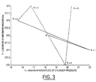
- FIG. 3 a graph representing the trajectories of five prior combustion events leading to a non-outlier is illustrated.
- Data sets (x and y) used for modelling and control are mostly deterministic data with a smaller percentage of noise included.
- the unique challenge of this particular data is that the desired state is one that is uniformly noisy, in the shape of an extended gaussian. When the system begins to exhibit undesirable behaviour, the path followed by the variables in time actually becomes more deterministic.
- controller 22 may use only cylinder pressure (x), only piston position (y), only angle, derivatives or integrals. The most successful combination, however, is five steps of x, y, and angle.
- FIG. 3 a graph representing the trajectories of five prior combustion events leading to a non-outlier in accordance with one embodiment of the present invention is illustrated. Beginning with the combustion event that occurred five cycles ago, k+5, and continuing through the present combustion event k; Event x y k+5 20.4 374 k+4 19.8 370 k+3 16.7 374 k+2 15.5 373 k+1 22.0 371 k 18.4 372
- a data set is collected from engine 12. Approximately 750 to 1000 x/y data points collected during the operation of engine 12 may be used. In the present example, the data set was selected to avoid any undesirable outliers among the points leading up to the target of interest. In testing it was found that data sets taken after engine 12 was operating for a period of time produced superior results in the neural network. For example, at least 6000 cycles after initial engine operation.
- Controller 16 begins by sensing a plurality of piston positions during a plurality of combustion events to generate a plurality of piston position signals in response to said piston positions. Controller 16 then senses a plurality of cylinder pressures during the same plurality of combustion events to generate a plurality of cylinder pressure signals in response to said cylinder pressures. Controller 16 then generates a plurality of angles formed by the plurality of trajectories of the past cylinder pressures plotted versus the past piston positions in time and collects these past angles, pressures and positions in a data set.
- the neural network is then trained upon the data set and controller 16 uses this trained neural network to predict undesirable cylinder pressure for future combustion events.
- controller 16 constantly compares the predicted undesirable cylinder pressures to actual cylinder pressures to determine an error rate. If the error rate is unacceptable (i.e. exceeds some predetermined threshold), then controller 16 re-train the neural network.
- the neural network is re-trained based upon a hybrid data set comprising a new (recently collected) data set and the original data set with a forgetting factor. Controller 16 then implements the re-trained neural network.
Landscapes
- Engineering & Computer Science (AREA)
- Chemical & Material Sciences (AREA)
- Combustion & Propulsion (AREA)
- Mechanical Engineering (AREA)
- General Engineering & Computer Science (AREA)
- Combined Controls Of Internal Combustion Engines (AREA)
- Measuring Fluid Pressure (AREA)
Abstract
Description
| Event | x | y |
| k+5 | 20.4 | 374 |
| k+4 | 19.8 | 370 |
| k+3 | 16.7 | 374 |
| k+2 | 15.5 | 373 |
| k+1 | 22.0 | 371 |
| k | 18.4 | 372 |
| Event | Slope | Angle |
| k+4 | 6.667 | |
| k+3 | -1.290 | - 43.69 |
| k+2 | 0.833 | -177.97 |
| k+1 | -0.308 | 33.92 |
| k | -0.278 | 91.58MM |
Claims (10)
- An apparatus for predicting cylinder pressure for on-vehicle control of an internal combustion engine, comprising:a piston sensor (12) coupled to a piston (24) located in said engine, said piston sensor (18) detecting a piston position and generating a piston position signal during a combustion event;a cylinder pressure sensor (20) coupled to a cylinder located in said engine, said cylinder pressure sensor detecting a cylinder pressure and generating a cylinder pressure signal during said combustion event; anda controller (16) coupled to said piston sensor (18) and said cylinder pressure sensor (20), said controller (16) receiving said piston position signal and said cylinder pressure signal, said controller (16) having a trained classifier predicting an undesirable cylinder pressure during a future combustion event based upon a plurality of past piston position signals correlated with a plurality of past cylinder pressure signals, said controller modifying said future combustion event in response to said undesirable cylinder pressure.
- An apparatus for predicting cylinder pressure for on-vehicle control of an internal combustion engine as claimed in claim 1, wherein said piston sensor comprises a crankshaft sensor coupled to a crankshaft located in said engine, said crankshaft sensor detecting a crankshaft angle and generating a crankshaft angle signal corresponding to piston position.
- An apparatus for predicting cylinder pressure for on-vehicle control of an internal combustion engine as claimed in claim 1, wherein said trained classifier comprises a radial basis function neural network.
- An apparatus for predicting cylinder pressure for on-vehicle control of an internal combustion engine as claimed in claim 1, wherein said controller modifies said future combustion event in response to said undesirable cylinder pressure comprises modifying a spark ignition timing to correct for said undesirable cylinder pressure.
- An apparatus for predicting cylinder pressure for on-vehicle control of an internal combustion engine as claimed in claim 1, wherein said controller modifies said future combustion event in response to said undesirable cylinder pressure comprises modifying an injected fuel amount to correct for said undesirable cylinder pressure.
- An apparatus for predicting cylinder pressure for on-vehicle control of an internal combustion engine as claimed in claim 1, wherein said controller predicts an undesirable cylinder pressure during a future combustion event based upon an angle formed by a trajectory of cylinder pressure during a combustion event plotted versus piston position during said combustion event in time.
- An apparatus for predicting cylinder pressure for on-vehicle control of an internal combustion engine as claimed in claim 6, wherein said controller predicts an undesirable cylinder pressure during a future combustion event based upon a plurality of past angles formed by the trajectories of past cylinder pressures plotted versus past piston positions in time.
- An apparatus for predicting cylinder pressure for on-vehicle control of an internal combustion engine as claimed in claim 1, wherein said neural network is trained using a data set comprising a plurality of cylinder pressures and a plurality of piston positions during a plurality of combustion events.
- An apparatus for predicting cylinder pressure for on-vehicle control of an internal combustion engine as claimed in claim 8, wherein said data set is taken after an initial engine-operating period or before an undesirable cylinder pressure.
- A method for predicting cylinder pressure for on-vehicle control of an internal combustion engine, comprising the steps of:sensing a piston position during a combustion event to generate a piston position signal in response to said piston position;sensing a cylinder pressure during said combustion event to generate a cylinder pressure signal in response to said cylinder pressure;receiving said cylinder pressure and said piston position;predicting an undesirable cylinder pressure during a future combustion event based upon an angle formed by a trajectory of cylinder pressure during a combustion event correlated versus piston position during said combustion event in time using a trained classifier; andmodifying said future combustion event in response to said undesirable cylinder pressure.
Applications Claiming Priority (2)
| Application Number | Priority Date | Filing Date | Title |
|---|---|---|---|
| US09/449,141 US6272426B1 (en) | 1999-11-24 | 1999-11-24 | Predicting cylinder pressure for on-vehicle control |
| US449141 | 1999-11-24 |
Publications (2)
| Publication Number | Publication Date |
|---|---|
| EP1103708A2 true EP1103708A2 (en) | 2001-05-30 |
| EP1103708A3 EP1103708A3 (en) | 2002-04-17 |
Family
ID=23783027
Family Applications (1)
| Application Number | Title | Priority Date | Filing Date |
|---|---|---|---|
| EP00309344A Withdrawn EP1103708A3 (en) | 1999-11-24 | 2000-10-24 | Predicting cylinder pressure for on-vehicle control |
Country Status (2)
| Country | Link |
|---|---|
| US (1) | US6272426B1 (en) |
| EP (1) | EP1103708A3 (en) |
Cited By (1)
| Publication number | Priority date | Publication date | Assignee | Title |
|---|---|---|---|---|
| GB2388925B (en) * | 2000-12-05 | 2005-07-27 | Detroit Diesel Corp | Method of controlling an internal combustion engine |
Families Citing this family (11)
| Publication number | Priority date | Publication date | Assignee | Title |
|---|---|---|---|---|
| SE519192C2 (en) * | 2000-05-17 | 2003-01-28 | Mecel Ab | Engine control method |
| US6553305B2 (en) * | 2000-12-29 | 2003-04-22 | Visteon Global Technologies, Inc. | Real time adaptive engine position estimation |
| US6557528B2 (en) * | 2001-08-30 | 2003-05-06 | Caterpillar Inc. | Method of controlling detonation in an internal combustion engine |
| US6782737B2 (en) | 2002-04-08 | 2004-08-31 | Cummins, Inc. | System for estimating peak cylinder pressure in an internal combustion engine |
| DE102004033072A1 (en) * | 2004-01-07 | 2005-07-28 | Robert Bosch Gmbh | Method and device for controlling an internal combustion engine |
| JP2007533911A (en) * | 2004-04-20 | 2007-11-22 | サウスウエスト リサーチ インスティテュート | Virtual cylinder pressure sensor with individual estimators for pressure related values |
| JP4472588B2 (en) * | 2005-06-23 | 2010-06-02 | 日立オートモティブシステムズ株式会社 | Cylinder discrimination device for internal combustion engine |
| US9429096B2 (en) * | 2011-09-15 | 2016-08-30 | Robert Bosch Gmbh | Predictive modeling and reducing cyclic variability in autoignition engines |
| US11948703B2 (en) | 2019-04-01 | 2024-04-02 | Anya L. Getman | Methods and devices for electrically insulating a power line |
| JP2019157652A (en) * | 2018-03-07 | 2019-09-19 | トヨタ自動車株式会社 | Control device of internal combustion engine |
| JP6593560B1 (en) * | 2019-02-15 | 2019-10-23 | トヨタ自動車株式会社 | Internal combustion engine misfire detection device, internal combustion engine misfire detection system, data analysis device, and internal combustion engine control device |
Family Cites Families (4)
| Publication number | Priority date | Publication date | Assignee | Title |
|---|---|---|---|---|
| JP2717665B2 (en) | 1988-05-31 | 1998-02-18 | 株式会社豊田中央研究所 | Combustion prediction determination device for internal combustion engine |
| US5076098A (en) | 1990-02-21 | 1991-12-31 | Nissan Motor Company, Limited | System for detecting combustion state in internal combustion engine |
| JP2937011B2 (en) * | 1994-04-26 | 1999-08-23 | 日産自動車株式会社 | Engine air-fuel ratio control device |
| WO1997033082A1 (en) * | 1996-03-08 | 1997-09-12 | Mitsubishi Jidosha Kogyo Kabushiki Kaisha | Device for controlling cylinder fuel injection type internal combustion engine |
-
1999
- 1999-11-24 US US09/449,141 patent/US6272426B1/en not_active Expired - Fee Related
-
2000
- 2000-10-24 EP EP00309344A patent/EP1103708A3/en not_active Withdrawn
Cited By (1)
| Publication number | Priority date | Publication date | Assignee | Title |
|---|---|---|---|---|
| GB2388925B (en) * | 2000-12-05 | 2005-07-27 | Detroit Diesel Corp | Method of controlling an internal combustion engine |
Also Published As
| Publication number | Publication date |
|---|---|
| US6272426B1 (en) | 2001-08-07 |
| EP1103708A3 (en) | 2002-04-17 |
Similar Documents
| Publication | Publication Date | Title |
|---|---|---|
| EP1103708A2 (en) | Predicting cylinder pressure for on-vehicle control | |
| EP0357197B1 (en) | Predictive spark timing method | |
| EP1528241A2 (en) | Estimation of intake gas temperature in internal combustion engine | |
| US20050187700A1 (en) | System and method for diagnosing and calibrating internal combustion engines | |
| EP1098184A1 (en) | Preignition detecting system and method | |
| US7292926B2 (en) | Method and device for estimation of combustion chamber pressure | |
| CN114930010B (en) | Control device for internal combustion engine | |
| US20070192019A1 (en) | Method for estimating quantity of fuel injected | |
| US20030061869A1 (en) | Method for determining the position of the combustion | |
| KR102372257B1 (en) | Method for diagnosing misfires of an internal combustion engine | |
| CN101451473B (en) | Engine operation method and control or adjustment device for engine | |
| Howlett et al. | Neural network techniques for monitoring and control of internal combustion engines | |
| US6234145B1 (en) | Engine control device | |
| JPS6315466B2 (en) | ||
| US20010020465A1 (en) | Method for detecting combustion misfires and cylinder equalization in internal combustion engines with knock control | |
| US5471869A (en) | Combustion state-detecting system for internal combustion engines | |
| US5427069A (en) | Apparatus and method for fuel injection timing control of an internal combustion engine | |
| EP2351923B1 (en) | Cylinder intake air amount calculating apparatus for internal combustion engine | |
| US5901684A (en) | Method for processing crankshaft speed fluctuations for control applications | |
| WO2015087134A1 (en) | Diagnostic system for internal combustion engine | |
| US4936275A (en) | Ignition control device for internal combustion engine with prediction of timing ratio | |
| Müller et al. | Engine control using neural networks: a new method in engine management systems | |
| JP5630970B2 (en) | Control device, control method and computer program for driving internal combustion engine | |
| KR102350839B1 (en) | Method for cylinder balancing of an internal combustion engine | |
| KR20080011434A (en) | Method and apparatus for determining the ratio between fuel mass burned in a cylinder of an internal combustion engine and fuel mass supplied into the cylinder |
Legal Events
| Date | Code | Title | Description |
|---|---|---|---|
| PUAI | Public reference made under article 153(3) epc to a published international application that has entered the european phase |
Free format text: ORIGINAL CODE: 0009012 |
|
| AK | Designated contracting states |
Kind code of ref document: A2 Designated state(s): DE GB SE Kind code of ref document: A2 Designated state(s): AT BE CH CY DE DK ES FI FR GB GR IE IT LI LU MC NL PT SE |
|
| AX | Request for extension of the european patent |
Free format text: AL;LT;LV;MK;RO;SI |
|
| PUAL | Search report despatched |
Free format text: ORIGINAL CODE: 0009013 |
|
| AK | Designated contracting states |
Kind code of ref document: A3 Designated state(s): AT BE CH CY DE DK ES FI FR GB GR IE IT LI LU MC NL PT SE |
|
| AX | Request for extension of the european patent |
Free format text: AL;LT;LV;MK;RO;SI |
|
| 17P | Request for examination filed |
Effective date: 20020910 |
|
| AKX | Designation fees paid |
Free format text: DE GB SE |
|
| STAA | Information on the status of an ep patent application or granted ep patent |
Free format text: STATUS: THE APPLICATION HAS BEEN WITHDRAWN |
|
| 18W | Application withdrawn |
Effective date: 20041111 |