EP1103627A2 - Method for thermal barrier coating - Google Patents
Method for thermal barrier coating Download PDFInfo
- Publication number
- EP1103627A2 EP1103627A2 EP00310229A EP00310229A EP1103627A2 EP 1103627 A2 EP1103627 A2 EP 1103627A2 EP 00310229 A EP00310229 A EP 00310229A EP 00310229 A EP00310229 A EP 00310229A EP 1103627 A2 EP1103627 A2 EP 1103627A2
- Authority
- EP
- European Patent Office
- Prior art keywords
- piece
- thermal barrier
- hole
- barrier coating
- spraying
- Prior art date
- Legal status (The legal status is an assumption and is not a legal conclusion. Google has not performed a legal analysis and makes no representation as to the accuracy of the status listed.)
- Withdrawn
Links
- XDTMQSROBMDMFD-UHFFFAOYSA-N C1CCCCC1 Chemical compound C1CCCCC1 XDTMQSROBMDMFD-UHFFFAOYSA-N 0.000 description 1
Images


Classifications
-
- C—CHEMISTRY; METALLURGY
- C23—COATING METALLIC MATERIAL; COATING MATERIAL WITH METALLIC MATERIAL; CHEMICAL SURFACE TREATMENT; DIFFUSION TREATMENT OF METALLIC MATERIAL; COATING BY VACUUM EVAPORATION, BY SPUTTERING, BY ION IMPLANTATION OR BY CHEMICAL VAPOUR DEPOSITION, IN GENERAL; INHIBITING CORROSION OF METALLIC MATERIAL OR INCRUSTATION IN GENERAL
- C23C—COATING METALLIC MATERIAL; COATING MATERIAL WITH METALLIC MATERIAL; SURFACE TREATMENT OF METALLIC MATERIAL BY DIFFUSION INTO THE SURFACE, BY CHEMICAL CONVERSION OR SUBSTITUTION; COATING BY VACUUM EVAPORATION, BY SPUTTERING, BY ION IMPLANTATION OR BY CHEMICAL VAPOUR DEPOSITION, IN GENERAL
- C23C4/00—Coating by spraying the coating material in the molten state, e.g. by flame, plasma or electric discharge
- C23C4/02—Pretreatment of the material to be coated, e.g. for coating on selected surface areas
-
- B—PERFORMING OPERATIONS; TRANSPORTING
- B23—MACHINE TOOLS; METAL-WORKING NOT OTHERWISE PROVIDED FOR
- B23K—SOLDERING OR UNSOLDERING; WELDING; CLADDING OR PLATING BY SOLDERING OR WELDING; CUTTING BY APPLYING HEAT LOCALLY, e.g. FLAME CUTTING; WORKING BY LASER BEAM
- B23K26/00—Working by laser beam, e.g. welding, cutting or boring
- B23K26/36—Removing material
- B23K26/38—Removing material by boring or cutting
- B23K26/382—Removing material by boring or cutting by boring
- B23K26/389—Removing material by boring or cutting by boring of fluid openings, e.g. nozzles, jets
-
- B—PERFORMING OPERATIONS; TRANSPORTING
- B23—MACHINE TOOLS; METAL-WORKING NOT OTHERWISE PROVIDED FOR
- B23K—SOLDERING OR UNSOLDERING; WELDING; CLADDING OR PLATING BY SOLDERING OR WELDING; CUTTING BY APPLYING HEAT LOCALLY, e.g. FLAME CUTTING; WORKING BY LASER BEAM
- B23K26/00—Working by laser beam, e.g. welding, cutting or boring
- B23K26/36—Removing material
- B23K26/40—Removing material taking account of the properties of the material involved
-
- B—PERFORMING OPERATIONS; TRANSPORTING
- B23—MACHINE TOOLS; METAL-WORKING NOT OTHERWISE PROVIDED FOR
- B23K—SOLDERING OR UNSOLDERING; WELDING; CLADDING OR PLATING BY SOLDERING OR WELDING; CUTTING BY APPLYING HEAT LOCALLY, e.g. FLAME CUTTING; WORKING BY LASER BEAM
- B23K2103/00—Materials to be soldered, welded or cut
- B23K2103/16—Composite materials
- B23K2103/166—Multilayered materials
- B23K2103/172—Multilayered materials wherein at least one of the layers is non-metallic
-
- B—PERFORMING OPERATIONS; TRANSPORTING
- B23—MACHINE TOOLS; METAL-WORKING NOT OTHERWISE PROVIDED FOR
- B23K—SOLDERING OR UNSOLDERING; WELDING; CLADDING OR PLATING BY SOLDERING OR WELDING; CUTTING BY APPLYING HEAT LOCALLY, e.g. FLAME CUTTING; WORKING BY LASER BEAM
- B23K2103/00—Materials to be soldered, welded or cut
- B23K2103/50—Inorganic materials other than metals or composite materials
- B23K2103/52—Ceramics
-
- B—PERFORMING OPERATIONS; TRANSPORTING
- B23—MACHINE TOOLS; METAL-WORKING NOT OTHERWISE PROVIDED FOR
- B23P—METAL-WORKING NOT OTHERWISE PROVIDED FOR; COMBINED OPERATIONS; UNIVERSAL MACHINE TOOLS
- B23P2700/00—Indexing scheme relating to the articles being treated, e.g. manufactured, repaired, assembled, connected or other operations covered in the subgroups
- B23P2700/06—Cooling passages of turbine components, e.g. unblocking or preventing blocking of cooling passages of turbine components
-
- Y—GENERAL TAGGING OF NEW TECHNOLOGICAL DEVELOPMENTS; GENERAL TAGGING OF CROSS-SECTIONAL TECHNOLOGIES SPANNING OVER SEVERAL SECTIONS OF THE IPC; TECHNICAL SUBJECTS COVERED BY FORMER USPC CROSS-REFERENCE ART COLLECTIONS [XRACs] AND DIGESTS
- Y02—TECHNOLOGIES OR APPLICATIONS FOR MITIGATION OR ADAPTATION AGAINST CLIMATE CHANGE
- Y02T—CLIMATE CHANGE MITIGATION TECHNOLOGIES RELATED TO TRANSPORTATION
- Y02T50/00—Aeronautics or air transport
- Y02T50/60—Efficient propulsion technologies, e.g. for aircraft
Definitions
- the present invention relates generally to a method of applying thermal barrier coatings to a metal piece, and more particularly to a method of coating a piece having cooling holes.
- cooling air is sometimes blown over the piece.
- cooling holes are formed in the liner for directing film cooling air through the liner and over surfaces of the liner exposed to high temperatures.
- the film cooling air cools the liner and forms a fluid barrier between the liner and hot gases which flow through the engine.
- the film of cooling air prevents the gases from directly contacting the liner.
- thermal barrier coatings are applied to surfaces of metal pieces exposed to high temperature environments to reduce the amount of heat which is transferred to the metal substrate. However, if the thermal barrier coatings are damaged (e.g., by field exposure or handling damage) the protection offered by the coatings may be compromised.
- damaged thermal barrier coating can be repaired by conventional methods of stripping the damaged coating and applying a new coating to the piece, cooling holes must be masked before applying the new coating or drilled (e.g., by laser drilling) after applying the new coating to ensure the holes are not blocked by the coating. These masking or drilling operations increase the cost of repairing damaged thermal barrier coatings.
- a method of applying thermal barrier coating systems to a metal piece having a cooling hole extending along a central axis through the piece from a first surface of the piece to a second surface of the piece opposite the first surface comprising the steps of: spraying a bond coat on said first surface of the piece at an angle with respect to the central axis of the hole and to a thickness selected in combination with the angle at which the bond coat is sprayed to prevent the bond coat from entirely filling the hole; spraying a thermal barrier coating on the bond coat at an angle with respect to the central axis of the hole and to a thickness selected in combination with the angle at which the thermal barrier coating is sprayed to prevent the thermal barrier coating from entirely filling the hole; and spraying a high pressure fluid jet from a nozzle toward the hole and in a direction generally parallel to the central axis of the hole, said fluid jet being substantially free of solid particulate thereby permitting the jet to remove the bond coat and the thermal barrier coating from the hole without
- the step of spraying the high pressure fluid jet from the nozzle may be performed at least twice, once after the step of spraying the bond coat but before the step of spraying the thermal barrier coating to remove the bond coat from the hole, and again after the step of spraying the thermal barrier coating to remove the thermal barrier coating from the hole.
- the thermal barrier coating may be sprayed on said first surface at an angle of incidence with respect to said first surface of at least 45 degrees.
- the thermal barrier coating may be sprayed on said first surface in at least two coats and the step of spraying the fluid from the nozzle is performed at least twice, once after spraying a first coat of said coats of thermal barrier coating and again after spraying a second coat of said coats of thermal barrier coating.
- the fluid jet may be sprayed from the nozzle toward the second surface of the piece.
- the fluid jet may be sprayed from the nozzle at a pressure of between about 5000 pounds per square inch and about 50,000 pounds per square inch. he fluid jet may be sprayed from the nozzle at a pressure of about 20,000 pounds per square inch.
- the bond coat may be sprayed on said first surface of the piece to a thickness of between about 0.004 inches and about 0.010 inches.
- the bond coat may be sprayed on said first surface of the piece to a thickness of between about 0.004 inches and about 0.006 inches.
- the thermal barrier coating may be sprayed on said first surface of the piece in at least one coat having a thickness of between about 0.003 inches and about 0.015 inches.
- the thermal barrier coating may be sprayed on said first surface of the piece in at least one coat having a thickness of about 0.010 inches.
- a method of applying thermal barrier coating systems to a metal piece having a series of cooling holes, each of said holes extending along a central axis through the piece from a first surface of the piece to a second surface of the piece opposite the first surface comprising the steps of: spraying a bond coat on said first surface of the piece at an oblique angle with respect to the central axis of the hole and to a thickness selected in combination with the angle at which the bond coat is sprayed to prevent the bond coat from entirely filling each of said series of holes; spraying a thermal barrier coating on the bond coat at an oblique angle with respect to the central axis of the hole and to a thickness selected in combination with the angle at which the thermal barrier coating is sprayed to prevent the thermal barrier coating from entirely filling each of said series of holes; and spraying a high pressure water jet toward each of said holes from a nozzle facing the second surface of the piece and in a direction generally parallel to the central axis of the
- the piece may be circular, said series of holes may be aligned in a tangential row, and said piece may be rotated to move the piece with respect to the nozzle and to align the nozzle with each hole of said series of holes as the high pressure water jet is sprayed.
- the piece may be moved relative to the nozzle at a rate of between about five inches per minute and about fifty inches per minute.
- the piece may be moved relative to the nozzle at a rate of about twenty inches per minute.
- a method of applying coating material to a work piece comprising the steps of: spraying a first coat on said first surface of the piece at an oblique angle with respect to an axis of the hole and to a thickness selected in combination with the angle at which the first coat is sprayed to prevent the first coat from entirely filling each of said series of holes; spraying a second coat over the first coat at an oblique angle with respect to an axis of the hole and to a thickness selected in combination with the angle at which the second coat is sprayed to prevent the second coat from entirely filling each of said series of holes; and spraying a fluid jet toward each of said holes from the second surface of the piece, said fluid jet being substantially free of solid particulate thereby permitting the jet to remove coat material
- the present invention includes a method of applying thermal barrier coating systems to a metal piece having a cooling hole extending along a central axis through the piece from a first surface of the piece to a second surface of the piece opposite the first surface.
- the method includes spraying a bond coat on the first surface of the piece and spraying a thermal barrier coating on the bond coat.
- the method includes spraying a high pressure fluid jet from a nozzle toward the hole and in a direction generally parallel to the central axis of the hole.
- the fluid jet is substantially free of solid particulate thereby permitting the jet to remove the bond coat and the thermal barrier coating from the hole without removing metal from the piece.
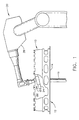
- a metal piece such as an outer combustion chamber liner of an aircraft engine is designated in its entirety by the reference number 10.
- the metal piece 10 may be a new piece which has never had a thermal barrier coating system or it may be a partially repaired piece from which damaged thermal barrier coating has been removed by conventional mechanical and/or chemical stripping processes.
- the metal piece 10 is received by a conventional turntable, generally designated by 12, having a support 14 sized and shaped for receiving the piece and a central vertical shaft 16 for rotating the support.
- a conventional thermal barrier coating spray apparatus, generally designated by 20, is provided adjacent the turntable 12 for applying a thermal barrier system (i.e., bond coats and thermal barrier coatings) to a first surface 22 of the metal piece 10.
- a thermal barrier system i.e., bond coats and thermal barrier coatings
- the apparatus 20 includes a spray head 24 having a nozzle 26 through which the thermal barrier system is sprayed and a robotic arm 28 for manipulating the head into position relative to the metal piece 10.
- the thermal barrier coating spray apparatus 20 of the preferred embodiment is an ATCS plasma system with an 8-axis computer numerically controlled Fanuc robot system available from Sulzer Metco of Westbury, New York.
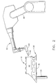
- Fig. 2 illustrates the metal piece 10 received by another conventional turntable, generally designated by 30, comprising a support 32 and a central vertical shaft 34 for rotating the support.
- a conventional water jet apparatus, generally designated by 40, adjacent the turntable 30 sprays water toward the metal piece 10 onto a second surface 42 of the piece opposite the first surface 22 (Fig. 1).
- the water jet apparatus 40 includes a spray head 44 having a nozzle 46 for spraying a high pressure jet of fluid such as water toward the piece and a robotic arm 46 for manipulating the head into position relative to the metal piece 10.
- the water jet apparatus 40 of the preferred embodiment is a Model No. 1015 5-axis computer numerically controlled water jet system available from Progressive Technologies of Grand Rapids, Michigan.
- thermal barrier coating spray apparatus and water jet apparatus are conventional and well understood by those skilled in the art, they will not be described in further detail.
- the metal piece 10 has a series of cooling holes (only one of which is shown) defined by tubular surfaces 50 aligned in a row extending tangentially around the piece.
- Each cooling hole 50 extends along a central axis 52 through the piece from the first surface 22 of the piece to the second surface 42 of the piece opposite the first surface.
- the central axis 52 of the hole is oriented at an angle 54 (e.g., twenty degrees) with respect to the first surface 22 of the piece 10.
- the size and orientation of the hole are not critical to the present invention.
- the thermal barrier coating spray apparatus 20 is operable to spray a bond coat 60 such as NiCrAIY on the first surface 22 of the piece 10 at a spray angle 62 measured with respect to the central axis 52 of the hole and to a thickness 64 selected in combination with the angle 62 to prevent the bond coat from entirely filling the hole.
- a spray angle 62 may vary without departing from the scope of the present invention, the angle 62 is preferably greater than ninety degrees (i.e., oblique) to minimize the amount of bond coat sprayed on the surface 50 defining the hole opposite the spray nozzle 26.
- the bond coat 60 is preferably sprayed on the first surface 22 at an angle of incidence 66 measured with respect to the first surface of at least about 45 degrees. Angles of incidence 66 less than about 45 degrees tend to cause the coat 60 to have unmelted areas, voids and lower tensile strength.
- the spray angle 62 and the thickness 64 are selected in combination to prevent the bond coat from entirely filling the hole.
- the bond coat 60 may be sprayed on the first surface 22 at an angle of incidence 66 of about 45 degrees and an angle 62 with respect to the central axis 52 of the hole of about 115 degrees.
- the bond coat 60 is sprayed to a thickness 64 of between about 0.004 inches and about 0.010 inches, and more preferably to a thickness of between about 0.004 inches and about 0.006 inches.
- the angles and thickness may be varied without departing from the scope of the present invention.
- the angle 62 measured with respect to the central axis 52 and the thickness 66 be selected so that the bond coat does not entirely fill the hole.
- the unfilled portion of the hole provides a pilot hole so that the water jet apparatus can remove the bond coat 60 from the hole as will be explained below.
- the piece 10 is placed on the turntable support 30 adjacent the water jet apparatus 40.
- the water jet apparatus 40 sprays a high pressure water jet toward the hole from a nozzle 46 facing the second surface 42 of the piece 10 and in a direction 68 generally parallel to the central axis 52 of the hole.
- the water jet is substantially free of solid particulate so the jet removes only the bond coat 60 from the hole 52 without removing metal from the piece 10.
- a pilot hole is needed to permit the water jet to remove the bond coat 60 from the hole. This is because the water jet abrades the bond coat 60 rather than pushing it from the hole. If the pilot hole is not present, the abrasion capability of the water jet is reduced.
- the water jet apparatus of the preferred embodiment produces a water jet having a pressure of between about 5000 pounds per square inch and about 50,000 pounds per square inch.
- the water jet is sprayed from the nozzle 46 at a pressure of about 20,000 pounds per square inch.
- the thermal barrier coating spray apparatus 20 sprays a thermal barrier coating 70 such as yttria stabilized zirconia on the bond coat 60 at a spray angle 72 measured with respect to the central axis 52 of the hole and to a thickness 74 selected in combination with the angle at which the thermal barrier coating is sprayed to prevent the thermal barrier coating from entirely filling the hole.
- the thermal barrier coating 70 is preferably sprayed on the bond coat 60 at an angle of incidence 76 with respect to the bond coat surface of at least about 45 degrees. Angles of incidence 76 less than about 45 degrees tend to cause the coating 70 to have unmelted areas, voids and lower tensile strength.
- the spray angle 72 and the thickness 74 are selected in combination to prevent the thermal barrier coating from entirely filling the hole.
- the thermal barrier coating 70 may be sprayed on the bond coat 60 at an angle of incidence 76 of about 45 degrees and a spray angle 72 of about 115 degrees.
- the coating 70 is sprayed in at least one coat having a thickness 74 of between about 0.003 inches and about 0.015 inches.
- the coating 70 is sprayed in a coat having a thickness 74 of about 0.010 inches.
- the angles and thickness may be varied without departing from the scope of the present invention. However, it is desirable that the spray angle 72 and the thickness 74 be selected so that the coating 70 does not entirely fill the hole. As with the bond coat, leaving a pilot hole in the thermal barrier coating enables the water jet to remove the coating 70 from the hole.
- the piece 10 is placed on the turntable support 30 adjacent the water jet apparatus 40 (Fig. 6).
- the water jet apparatus 40 sprays a high pressure water jet toward the hole from the nozzle 46 facing the second surface 42 of the piece 10 and in a direction 78 generally parallel to the central axis 52 of the hole to remove thermal barrier coating from the hole. Because the water jet is substantially free of solid particulate, the jet only removes the thermal barrier coating 70 from the hole without removing metal from the piece 10.
- the water jet pressure may vary without departing from the scope of the present invention, in the preferred embodiment the water jet pressure used during this spraying step is identical to the pressure used during the prior spraying step.
- thermal barrier coating 70 After the thermal barrier coating 70 is removed from the hole, additional layers of thermal barrier coating (not shown) may be applied to the piece 10 to build the total coating thickness. Preferably, the coating 70 is removed from the hole after applying each layer. As will be appreciated by those skilled in the art, the step of spraying the piece with the water jet after the bond coat 60 is applied and before the thermal barrier coating 70 is applied may be omitted if the combined thickness of the layers is thin enough that they do not entirely fill the hole thereby allowing the layers to be removed together.
- either the piece or the water jet nozzle 46 may be moved with respect to the other to sequentially align the water jet with each of the holes in the series.
- the piece 10 is circular and the series of holes is oriented in a row extending tangentially around the piece, the piece may be rotated to move the piece with respect to the nozzle 46 and to align the nozzle with each hole of the series.
- a motor (not shown) connected the shaft 34 may be used to continuously rotate the turntable 30 and piece 10.
- the piece 10 and the nozzle 46 may be moved at other rates without departing from the scope of the present invention, in the preferred embodiment they are moved at a relative speed of between about five inches per minute and about fifty inches per minute. In a particularly preferred embodiment, the piece 10 is moved relative to the nozzle 46 at a rate of about twenty inches per minute.
- the turntable 30 of the preferred embodiment rotates continuously, it is envisioned that the turntable may be rotated intermittently so the water jet dwells when aligned with each hole.
Landscapes
- Engineering & Computer Science (AREA)
- Physics & Mathematics (AREA)
- Optics & Photonics (AREA)
- Plasma & Fusion (AREA)
- Mechanical Engineering (AREA)
- Chemical & Material Sciences (AREA)
- Chemical Kinetics & Catalysis (AREA)
- Materials Engineering (AREA)
- Metallurgy (AREA)
- Organic Chemistry (AREA)
- Application Of Or Painting With Fluid Materials (AREA)
- Coating By Spraying Or Casting (AREA)
Abstract
Description
Claims (6)
- A method of applying thermal barrier coating systems s to a metal piece (10) having a cooling hole extending along a central axis (52) through the piece (10) from a first surface (22) of the piece (10) to a second surface (42) of the piece (10) opposite the first surface (22), said method comprising the steps of:spraying a bond coat (60) on said first surface (22) of the piece (10) at an angle (62) with respect to the central axis (52) of the hole and to a thickness (64) selected in combination with the angle (62) at which the bond coat (60) is sprayed to prevent the bond coat (60) from entirely filling the hole;spraying a thermal barrier coating (70) on the bond coat (60) at an angle (72) with respect to the central axis (52) of the hole and to a thickness (74) selected in combination with the angle (72) at which the thermal barrier coating (70) is sprayed to prevent the thermal barrier coating (70) from entirely filling the hole; andspraying a high pressure fluid jet from a nozzle (46) toward the hole and in a direction generally parallel to the central axis (52) of the hole, said fluid jet being substantially free of solid particulate thereby permitting the jet to remove the bond coat (60) and the thermal barrier coating (70) from the hole without removing metal from the piece (10).
- A method as set forth in claim 1 wherein the step of spraying the high pressure fluid jet from the nozzle (46) is performed at least twice, once after the step of spraying the bond coat (60) but before the step of spraying the thermal barrier coating (70) to remove the bond coat (60) from the hole, and again after the step of spraying the thermal barrier coating (70) to remove the thermal barrier coating (70) from the hole.
- A method as set forth in claim 1 or 2 wherein the thermal barrier coating (70) is sprayed on said first surface (22) in at least two coats and the step of spraying the fluid from the nozzle (46) is performed at least twice, once after spraying a first coat of said coats of thermal barrier coating (70) and again after spraying a second coat of said coats of thermal barrier coating (70).
- A method as set forth in claim 1, 2 or 3 wherein the fluid jet is sprayed from the nozzle (46) toward the second surface (42) of the piece (10).
- A method of applying thermal barrier coating systems to a metal piece (10) having a series of cooling holes, each of said holes extending along a central axis (52) through the piece (10) from a first surface (22) of the piece (10) to a second surface (42) of the piece (10) opposite the first surface (22), said method comprising the steps of:spraying a bond coat (60) on said first surface (22) of the piece (10) at an oblique angle (62) with respect to the central axis (52) of the hole and to a thickness (64) selected in combination with the angle (62) at which the bond coat (60) is sprayed to prevent the bond coat (60) from entirely filling each of said series of holes;spraying a thermal barrier coating (70) on the bond coat (60) at an oblique angle (72) with respect to the central axis (52) of the hole and to a thickness (74) selected in combination with the angle (72) at which the thermal barrier coating (70) is sprayed to prevent the thermal barrier coating (70) from entirely filling each of said series of holes; andspraying a high pressure water jet toward each of said holes from a nozzle (46) facing the second surface (42) of the piece (10) and in a direction generally parallel to the central axis (52) of the respective hole, said water jet being substantially free of solid particulate thereby permitting the jet to remove the bond coat (60) and the thermal barrier coating (70) from the respective hole without removing metal from the piece (10).
- A method as set forth in claim 5 wherein the piece (10) is circular, said series of holes are aligned in a tangential row, and said piece (10) is rotated to move the piece (10) with respect to the nozzle (46) and to align the nozzle (46) with each hole of said series of holes as the high pressure water jet is sprayed.
Applications Claiming Priority (2)
| Application Number | Priority Date | Filing Date | Title |
|---|---|---|---|
| US44859599A | 1999-11-24 | 1999-11-24 | |
| US448595 | 2003-05-30 |
Publications (2)
| Publication Number | Publication Date |
|---|---|
| EP1103627A2 true EP1103627A2 (en) | 2001-05-30 |
| EP1103627A3 EP1103627A3 (en) | 2002-12-18 |
Family
ID=23780930
Family Applications (1)
| Application Number | Title | Priority Date | Filing Date |
|---|---|---|---|
| EP00310229A Withdrawn EP1103627A3 (en) | 1999-11-24 | 2000-11-17 | Method for thermal barrier coating |
Country Status (4)
| Country | Link |
|---|---|
| US (2) | US20010006707A1 (en) |
| EP (1) | EP1103627A3 (en) |
| JP (1) | JP2001214251A (en) |
| SG (1) | SG127668A1 (en) |
Cited By (8)
| Publication number | Priority date | Publication date | Assignee | Title |
|---|---|---|---|---|
| EP1275749A1 (en) | 2001-07-13 | 2003-01-15 | General Electric Company | Method for thermal barrier coating and a liner made using said method |
| EP1340587A3 (en) * | 2002-03-01 | 2003-12-17 | General Electric Company | Process of removing a coating deposit from a through-hole in a component and component processed thereby |
| EP1887097A3 (en) * | 2006-07-28 | 2008-05-21 | General Electric Company | Method for concurrent thermal spray and cooling hole cleaning |
| EP1437194A3 (en) * | 2003-01-10 | 2009-11-04 | General Electric Company | Process of removing a ceramic coating deposit in a surface hole of a component |
| US7805822B2 (en) | 2003-12-15 | 2010-10-05 | Turbocombustor Technology, Inc. | Process for removing thermal barrier coatings |
| DE102009023605A1 (en) * | 2009-06-02 | 2010-12-09 | Daimler Ag | Apparatus and method for thermal coating |
| WO2014003897A3 (en) * | 2012-06-30 | 2014-04-03 | General Electric Company | Process for selectively producing thermal barrier coatings on turbine hardware |
| WO2014077909A2 (en) | 2012-07-09 | 2014-05-22 | United Technologies Corporation | Multi-lobed cooling holes in gas turbine engine components having thermal barrier coatings |
Families Citing this family (20)
| Publication number | Priority date | Publication date | Assignee | Title |
|---|---|---|---|---|
| US6592948B1 (en) * | 2002-01-11 | 2003-07-15 | General Electric Company | Method for masking selected regions of a substrate |
| EP1350860A1 (en) * | 2002-04-04 | 2003-10-08 | ALSTOM (Switzerland) Ltd | Process of masking cooling holes of a gas turbine component |
| EP1365039A1 (en) * | 2002-05-24 | 2003-11-26 | ALSTOM (Switzerland) Ltd | Process of masking colling holes of a gas turbine component |
| US20040106360A1 (en) * | 2002-11-26 | 2004-06-03 | Gilbert Farmer | Method and apparatus for cleaning combustor liners |
| JP4561153B2 (en) * | 2004-04-09 | 2010-10-13 | 日産自動車株式会社 | Method for adjusting porosity of sprayed coating and cylinder block of engine in which porosity of inner surface of cylinder bore is adjusted by this method |
| US7216485B2 (en) * | 2004-09-03 | 2007-05-15 | General Electric Company | Adjusting airflow in turbine component by depositing overlay metallic coating |
| DE102005015153B4 (en) * | 2005-03-31 | 2017-03-09 | General Electric Technology Gmbh | Method for repairing or renewing cooling holes of a coated component and coated component with cooling holes of a gas turbine |
| EP1839801A1 (en) * | 2006-03-30 | 2007-10-03 | Siemens Aktiengesellschaft | Repairing method to restore components |
| US8673397B2 (en) * | 2010-11-10 | 2014-03-18 | General Electric Company | Methods of fabricating and coating a component |
| US8460760B2 (en) | 2010-11-30 | 2013-06-11 | United Technologies Corporation | Coating a perforated surface |
| US20120167389A1 (en) * | 2011-01-04 | 2012-07-05 | General Electric Company | Method for providing a film cooled article |
| JP6220346B2 (en) * | 2011-12-29 | 2017-10-25 | ゼネラル・エレクトリック・カンパニイ | Pressure masking system and method of use thereof |
| US20140141173A1 (en) * | 2012-11-16 | 2014-05-22 | General Electric Company | Method of applying a coating to a perforated substrate |
| US10563578B2 (en) * | 2015-02-18 | 2020-02-18 | Mra Systems, Llc | Acoustic liners and method of shaping an inlet of an acoustic liner |
| US10739433B2 (en) | 2016-03-21 | 2020-08-11 | Texas Instruments Incorporated | Calibrating body impedance measurement systems |
| JP6584684B2 (en) * | 2016-10-07 | 2019-10-02 | 株式会社前川製作所 | Welding equipment |
| US20200024951A1 (en) * | 2018-07-17 | 2020-01-23 | General Electric Company | Component for a turbine engine with a cooling hole |
| CN109136906B (en) * | 2018-10-23 | 2020-06-26 | 济南大学 | Preparation method of surface coating of drilling platform thruster |
| CN111876720B (en) * | 2020-07-22 | 2021-06-15 | 江苏理工学院 | Nozzle equipment for supersonic plasma spraying system |
| CN112063957B (en) * | 2020-09-21 | 2022-10-11 | 北京北冶功能材料有限公司 | Thermal barrier coating spraying method for diffusion cooling transition section of heavy-duty gas turbine |
Family Cites Families (5)
| Publication number | Priority date | Publication date | Assignee | Title |
|---|---|---|---|---|
| US4338360A (en) * | 1980-05-01 | 1982-07-06 | General Motors Corporation | Method for coating porous metal structure |
| JP3611607B2 (en) * | 1994-10-12 | 2005-01-19 | 石川島播磨重工業株式会社 | Cooling hole rework method for engine parts |
| JP3657331B2 (en) * | 1995-12-08 | 2005-06-08 | 石川島播磨重工業株式会社 | Cooling hole reworking method for engine parts and cooling hole reworking device used in the method |
| EP1029103B1 (en) * | 1997-11-03 | 2001-09-19 | Siemens Aktiengesellschaft | Coating method and device |
| GB9723762D0 (en) * | 1997-11-12 | 1998-01-07 | Rolls Royce Plc | A method of coating a component |
-
2000
- 2000-11-15 SG SG200006617A patent/SG127668A1/en unknown
- 2000-11-17 EP EP00310229A patent/EP1103627A3/en not_active Withdrawn
- 2000-11-22 JP JP2000355156A patent/JP2001214251A/en not_active Withdrawn
- 2000-12-14 US US09/736,893 patent/US20010006707A1/en not_active Abandoned
- 2000-12-20 US US09/742,841 patent/US20010001680A1/en not_active Abandoned
Cited By (14)
| Publication number | Priority date | Publication date | Assignee | Title |
|---|---|---|---|---|
| EP1275749A1 (en) | 2001-07-13 | 2003-01-15 | General Electric Company | Method for thermal barrier coating and a liner made using said method |
| EP1340587A3 (en) * | 2002-03-01 | 2003-12-17 | General Electric Company | Process of removing a coating deposit from a through-hole in a component and component processed thereby |
| US6908657B2 (en) | 2002-03-01 | 2005-06-21 | General Electric Company | Coated component with through-hole having improved surface finish |
| EP1437194A3 (en) * | 2003-01-10 | 2009-11-04 | General Electric Company | Process of removing a ceramic coating deposit in a surface hole of a component |
| US7805822B2 (en) | 2003-12-15 | 2010-10-05 | Turbocombustor Technology, Inc. | Process for removing thermal barrier coatings |
| EP1887097A3 (en) * | 2006-07-28 | 2008-05-21 | General Electric Company | Method for concurrent thermal spray and cooling hole cleaning |
| DE102009023605A1 (en) * | 2009-06-02 | 2010-12-09 | Daimler Ag | Apparatus and method for thermal coating |
| WO2014003897A3 (en) * | 2012-06-30 | 2014-04-03 | General Electric Company | Process for selectively producing thermal barrier coatings on turbine hardware |
| CN104411858A (en) * | 2012-06-30 | 2015-03-11 | 通用电气公司 | Process for selectively producing thermal barrier coatings on turbine hardware |
| CN104411858B (en) * | 2012-06-30 | 2017-05-03 | 通用电气公司 | Process for selectively producing thermal barrier coatings on turbine hardware |
| US10100650B2 (en) | 2012-06-30 | 2018-10-16 | General Electric Company | Process for selectively producing thermal barrier coatings on turbine hardware |
| EP2867381B1 (en) | 2012-06-30 | 2021-02-17 | General Electric Company | Process for selectively producing thermal barrier coatings on turbine hardware |
| WO2014077909A2 (en) | 2012-07-09 | 2014-05-22 | United Technologies Corporation | Multi-lobed cooling holes in gas turbine engine components having thermal barrier coatings |
| EP2870344A4 (en) * | 2012-07-09 | 2015-08-26 | United Technologies Corp | Multi-lobed cooling holes in gas turbine engine components having thermal barrier coatings |
Also Published As
| Publication number | Publication date |
|---|---|
| EP1103627A3 (en) | 2002-12-18 |
| US20010001680A1 (en) | 2001-05-24 |
| US20010006707A1 (en) | 2001-07-05 |
| JP2001214251A (en) | 2001-08-07 |
| SG127668A1 (en) | 2006-12-29 |
Similar Documents
| Publication | Publication Date | Title |
|---|---|---|
| EP1103627A2 (en) | Method for thermal barrier coating | |
| US6620457B2 (en) | Method for thermal barrier coating and a liner made using said method | |
| KR100198896B1 (en) | How to remove coating by liquid jet | |
| US6365222B1 (en) | Abradable coating applied with cold spray technique | |
| CA1149241A (en) | Method for coating porous metal structure | |
| EP0807744B1 (en) | A fluid cooled article with a protective coating and method of making the same | |
| US4402992A (en) | Covering solid, film cooled surfaces with a duplex thermal barrier coating | |
| US6955308B2 (en) | Process of selectively removing layers of a thermal barrier coating system | |
| EP1473378B1 (en) | Method for applying or repairing thermal barrier coatings | |
| CA2481111C (en) | Process of masking cooling holes of a gas turbine component | |
| US10272461B2 (en) | Method for masking cooling passages | |
| CN104178760B (en) | cold spray process | |
| CA2486590A1 (en) | Process of masking cooling holes of a gas turbine component | |
| JP2008025032A (en) | Masking system for the masking of crank chamber of internal combustion engine | |
| EP1464722B1 (en) | Method of applying environmental and bond coating to turbine flowpath parts | |
| US6561872B2 (en) | Method and apparatus for stripping coating |
Legal Events
| Date | Code | Title | Description |
|---|---|---|---|
| PUAI | Public reference made under article 153(3) epc to a published international application that has entered the european phase |
Free format text: ORIGINAL CODE: 0009012 |
|
| AK | Designated contracting states |
Kind code of ref document: A2 Designated state(s): AT BE CH CY DE DK ES FI FR GB GR IE IT LI LU MC NL PT SE TR |
|
| AX | Request for extension of the european patent |
Free format text: AL;LT;LV;MK;RO;SI |
|
| PUAL | Search report despatched |
Free format text: ORIGINAL CODE: 0009013 |
|
| AK | Designated contracting states |
Kind code of ref document: A3 Designated state(s): AT BE CH CY DE DK ES FI FR GB GR IE IT LI LU MC NL PT SE TR |
|
| AX | Request for extension of the european patent |
Free format text: AL;LT;LV;MK;RO;SI |
|
| RIC1 | Information provided on ipc code assigned before grant |
Free format text: 7C 23C 4/12 A, 7C 23C 4/18 B, 7C 23C 4/02 B |
|
| 17P | Request for examination filed |
Effective date: 20030618 |
|
| AKX | Designation fees paid |
Designated state(s): DE FR GB |
|
| 17Q | First examination report despatched |
Effective date: 20030917 |
|
| STAA | Information on the status of an ep patent application or granted ep patent |
Free format text: STATUS: THE APPLICATION IS DEEMED TO BE WITHDRAWN |
|
| 18D | Application deemed to be withdrawn |
Effective date: 20040128 |