EP1103227A1 - Operationswerkzeug - Google Patents
Operationswerkzeug Download PDFInfo
- Publication number
- EP1103227A1 EP1103227A1 EP00810999A EP00810999A EP1103227A1 EP 1103227 A1 EP1103227 A1 EP 1103227A1 EP 00810999 A EP00810999 A EP 00810999A EP 00810999 A EP00810999 A EP 00810999A EP 1103227 A1 EP1103227 A1 EP 1103227A1
- Authority
- EP
- European Patent Office
- Prior art keywords
- tool
- sleeve
- handle
- tool part
- handle part
- Prior art date
- Legal status (The legal status is an assumption and is not a legal conclusion. Google has not performed a legal analysis and makes no representation as to the accuracy of the status listed.)
- Granted
Links
Images


Classifications
-
- A—HUMAN NECESSITIES
- A61—MEDICAL OR VETERINARY SCIENCE; HYGIENE
- A61B—DIAGNOSIS; SURGERY; IDENTIFICATION
- A61B17/00—Surgical instruments, devices or methods
- A61B17/56—Surgical instruments or methods for treatment of bones or joints; Devices specially adapted therefor
- A61B17/58—Surgical instruments or methods for treatment of bones or joints; Devices specially adapted therefor for osteosynthesis, e.g. bone plates, screws or setting implements
- A61B17/88—Osteosynthesis instruments; Methods or means for implanting or extracting internal or external fixation devices
- A61B17/8875—Screwdrivers, spanners or wrenches
-
- B—PERFORMING OPERATIONS; TRANSPORTING
- B25—HAND TOOLS; PORTABLE POWER-DRIVEN TOOLS; MANIPULATORS
- B25B—TOOLS OR BENCH DEVICES NOT OTHERWISE PROVIDED FOR, FOR FASTENING, CONNECTING, DISENGAGING, OR HOLDING
- B25B23/00—Details of, or accessories for, spanners, wrenches, screwdrivers
- B25B23/0007—Connections or joints between tool parts
- B25B23/0042—Connection means between screwdriver handle and screwdriver shaft
-
- A—HUMAN NECESSITIES
- A61—MEDICAL OR VETERINARY SCIENCE; HYGIENE
- A61B—DIAGNOSIS; SURGERY; IDENTIFICATION
- A61B17/00—Surgical instruments, devices or methods
- A61B17/16—Instruments for performing osteoclasis; Drills or chisels for bones; Trepans
-
- A—HUMAN NECESSITIES
- A61—MEDICAL OR VETERINARY SCIENCE; HYGIENE
- A61B—DIAGNOSIS; SURGERY; IDENTIFICATION
- A61B17/00—Surgical instruments, devices or methods
- A61B17/28—Surgical forceps
- A61B17/29—Forceps for use in minimally invasive surgery
- A61B17/2909—Handles
-
- A—HUMAN NECESSITIES
- A61—MEDICAL OR VETERINARY SCIENCE; HYGIENE
- A61B—DIAGNOSIS; SURGERY; IDENTIFICATION
- A61B17/00—Surgical instruments, devices or methods
- A61B2017/0046—Surgical instruments, devices or methods with a releasable handle; with handle and operating part separable
- A61B2017/00464—Surgical instruments, devices or methods with a releasable handle; with handle and operating part separable for use with different instruments
-
- A—HUMAN NECESSITIES
- A61—MEDICAL OR VETERINARY SCIENCE; HYGIENE
- A61B—DIAGNOSIS; SURGERY; IDENTIFICATION
- A61B17/00—Surgical instruments, devices or methods
- A61B2017/00477—Coupling
Definitions
- the invention relates to a surgical tool for use in Operating room.
- Such surgical tools generally have Handle part on which the operating doctor grips and with which he does this Tool can operate, as well as a tool part with which the Processing is done. Handle part and tool part are firmly together connected.
- Surgical tools for use in the operating room are available in countless designs. The highest depending on the area of application Different tools must be simple and easy after an operation be reliably cleanable and sterilizable, provided that it is reusable tools.
- Existing surgical tools have handle parts from one Hard plastic, which is designed very differently depending on the area of application are.
- Existing handle parts can be divided into different types, some of which are mentioned below as examples.
- An example for such a type of handle part is a screwdriver handle, so a elongated, profiled handle, with which in particular pressure forces and Torques can be exerted.
- Another example of one Handle part is the so-called T-handle, with which in particular tensile forces and Torques can be exerted.
- Another example of such Handle part is the bulbous handle, with which in particular pressure forces and lateral lever forces can be exerted.
- handle part is the tactile handle, an essentially unprofiled elongated handle, which is particularly suitable for use, with which certain conditions are felt. Furthermore there there are quite a few other types of handles, not all individually here can be enumerated.
- Tool parts and the handle parts not only firmly, but also beyond are inextricably linked. Often they are typically out Stainless steel or other rustproof material Tool parts in the handle part, which is typically made of plastic poured or overmolded by the plastic of the handle part.
- Such surgical tools can be easily and reliably Clean in a way (e.g. using ultrasonic baths) and also sterilize (e.g. by steam sterilization).
- the invention seeks to remedy this. Therefore it is a task of the Invention to propose a surgical tool with which it is possible is to significantly reduce the storage costs for surgical tools, without but the diversity and availability of the different Reduce surgical tools. In addition, it must Surgical tool easy and reliable to clean and sterilize his.
- the surgical tool according to the invention for use in Operating room includes a handle part and a fixed with this handle part connected tool part, the connection of the handle part and Tool part is designed as a releasable connection.
- Another advantage is that the sterile storage of the handle parts and the Tool parts the operating doctor before the operation first a number of tool parts and a number of handle parts that he can select may be needed during surgery, and the ones actually needed The surgical tools are only finally available in the operating room compile or have compiled by assistants can.
- Surgical tool is with a receptacle at the distal end of the handle part equipped, in which the tool part is introduced, whereby on Tool part and means are provided on the receptacle, which are fixed Create a connection between the handle and tool part.
- This receptacle for the tool part preferably comprises one out of one hard, wear-resistant material manufactured sleeve that is inseparable from the Handle part is connected.
- the sleeve can e.g. made of ceramic or a hard, low-wear plastic. However, it is preferably off a hard, wear-resistant stainless metal such as from a Made of stainless steel and can be in a plastic forming the handle poured or injected, so that the entire handle is reliably cleanable and sterilizable.
- the separate manufacturability of the Sleeve and the pouring in after this production or injecting into a plastic also means from the manufacturing side a simplification.
- connection of the handle part and tool part can basically be be designed in a wide variety of ways.
- the embodiment is, however, the connection of the handle part and tool part designed as a screw connection. On the one hand, this is a safe, on the other hand an easily detachable and also reliably producible Connection.
- the handle part or the sleeve has a stop for the proximal end of the tool part.
- the Screw connection includes a clamping sleeve with a External thread and one with this external thread of the clamping sleeve interacting internal thread in the handle or in the sleeve.
- the instep cuff encloses the tool part and is in the direction of Longitudinal axis of the tool part can be moved along the tool part until Slings attached to the tool part and the clamping sleeve are intended to knock against each other.
- This training can first the tool part is inserted into the handle part or into the sleeve until the proximal end of the tool part against that in the handle part or in the sleeve provided stop. Then it can External thread of the clamping sleeve into the internal thread in the handle part or be screwed into the sleeve until the sling collar's sling means butt against the lifting gear on the tool part so that the tool part is then secured against axial displacement.
- both the stop in the grip part or in the sleeve and the proximal End of the tool part is conical in the shape of a circular cone.
- the Tension cuff at its proximal end with the external thread provided and has an inwardly projecting at its distal end Head start on. This projection protrudes into a recess on the outside Tool part into it, so that the movement of the clamping sleeve in Limited direction of the longitudinal axis of the tool part.
- connection between the handle part and the tool part can be designed in many different ways.
- the embodiment of the connection of the handle part and Tool part designed as a snap connection. That kind of connection is also a safe, easily detachable and reliably producible Connection.
- the Snap connection a snap cuff firmly connected to the tool part on, which is provided with resilient slats.
- This resilient slats each have a protrusion that with a corresponding projection at the distal end of the handle part or the sleeve in Intervention is.
- the lamellae protrude in the distal direction the handle part and are outside the handle part with an organ for Squeeze the slats together to release them from each other in the To be able to effect engaging projections.
- This Embodiment is characterized in that both the introduction of the tool part into the handle part and the production of a fixed Connection of handle part and tool part in a simple and reliable Way is possible.
- the release of the snap connection and It is very easy to remove the tool part from the handle part.
- the snap cuff can be made as a separate part and are only then connected to the tool part, for example by welding what the manufacture of each part simplified.
- the area of the handle part or the sleeve encloses the corresponding non-rotationally symmetrical area of the tool part, to be able to transmit a torque. This is the axial securing of the tool part in the handle part against sliding out and the transfer of Torques are functionally separated.
- the non-rotationally symmetrical area has a rectangular, preferably square cross-section.
- Such a Cross section is technically simple and well suited for that Torque transmission.
- the surgical tool set according to the invention comprises at least one Handle part and several tool parts, the tool parts in their proximal area are designed so that different tool parts picked up by one and the same grip part and firmly with this can be connected. This preserves the variety of tools or even increased and at the same time reduced storage costs.
- the doctor may even perform a number of operations prior to surgery Select handle parts and a number of tool parts that he may be needed during surgery, and only in the operating room Put together the desired combination of handle and tool part or have them put together by assistants.
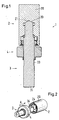
- FIG. 1 a Representation of the surgical tool in the assembly in one representation shows in longitudinal section
- FIG. 2 is a perspective view of the Surgical tool 1, in which handle part 2 and tool part 3 are not are interconnected.
- the surgical tool 1 already includes this addressed handle part 2 and the tool part 3 and a clamping sleeve 4.
- the individual parts are based on FIGS. 3, 4 and Fig. 5 described in more detail.
- Fig. 1 it can be seen that the fixed but releasable connection of the Handle part 2 and the tool part 3 is designed as a screw connection.
- Fig. 1 is only one of the handle part 2 from a hard, low-wear Material, e.g. Stainless steel, manufactured sleeve 20 to recognize (see also 6), which is a receptacle for the proximal end 30 of the tool part 3 (see also Fig. 4).
- This sleeve 20 cannot be detached from the handle part 2 connected by, for example, encapsulating a plastic or can be cast (not shown).
- Only the sleeve 20 shown since for the connection between Tool part 3 and handle part 2 of the plastic surrounding the sleeve is irrelevant.
- the sleeve 20 of the handle part 2, the tool part 3, and the tensioning cuff 4 separately producible parts, which are based on FIG. 3, 4 and 5 will be described.
- the clamping sleeve 4 with the tool part in even more detail descriptively connected, so the combination of tool part 3 and clamping sleeve 4 then together in the sleeve 20 of the handle part 2 can be used or after the use of the Surgical tool again together from the sleeve 20 of the Handle part 3 can be solved. This is indicated by the arrows A in FIG. 2 indicated symbolically.
- the tool part 3 can be seen in FIG. 3, the distal end 31 of the Tool part is shown here symbolically only as a stump of a shaft. On this distal end 31 of the tool part can e.g. the blade of one Screwdriver molded or a probe tip or a hook or much more.
- the proximal end 30 of the tool part 3 is frustoconical conical shape and works with one corresponding circular conical conical stop 21 in the Sleeve 20 together.
- the tool part 3 is inserted into the sleeve 20 and thus centered in the handle part 2.
- the clamping sleeve 4 which is a separately producible part, before inserting the tool part 3 into the handle part 2 or into the sleeve 20, connected to the tool part.
- clamping sleeve 4 is within the limit, which is represented by the recess 33, because the projection 43 strikes after crimping at the end of the recess 33 of the Tool part 3 when it is in the direction of the longitudinal axis along the Tool part 3 is moved outside on the tool part.
- the Tool part 3 with clamping collar applied to tool part 3 4 can be clearly seen in FIG. 2.
- sleeve 20 can be seen, which is the receptacle for the Tool part 3 represents.
- the circular conical stop 21 against which the frustoconical proximal end of the Tool part 3 when inserting tool part 3 into sleeve 20 bumps.
- the sleeve 20 another area 24, which is designed as a square and which at Introducing the tool part 3 into the sleeve 20 with an area 34 of the tool part cooperates, which is also designed as a square and in terms of shape and dimensions to match area 24 of FIG Sleeve 20 is formed to after inserting the tool part 3 in the Sleeve 20 (and thus in the handle part) to be able to transmit a torque.
- the square described here can be easily and create reliable way.
- the individual parts are - as in part already explained - in the following way to a surgical tool connected.
- the projection 43 in the recess 33 bent in, e.g. flanged so that the instep cuff 4 within the axial extent of the recess 33 in Direction of the longitudinal axis of the tool part 3 on the outside of the tool part can be moved along.
- the one provided with the tensioning cuff 4 Tool part 3 is then inserted with its proximal end first into sleeve 20 introduced in such a way that the area 34 (square) of the Tool part 3 fits into the area 24 of the sleeve 20.
- the tool part 3 is first introduced at the proximal end of the Tool part 3 centering, because the circular frustum trained proximal end 30 of the tool part 3 against the circular conical stop 21 of the sleeve 20 comes to rest.
- the tool part is centered at the distal end of the sleeve 20 and also the clamping sleeve 4 due to the pitch of the thread in moved proximal direction along the longitudinal axis of the tool part 3 becomes.
- the area 45 of the clamping sleeve 4 can e.g. with a knurling be provided to screw the clamping sleeve 4 into the sleeve 20 to facilitate it.
- the tensioning cuff 4 will continue into the Screwed sleeve 20 until the inwardly projecting projection 43 against the proximal boundary of the recess 33 of the tool part 3 abuts.
- the tool part 3 is thus secured against axial sliding out (clamped) and otherwise - as already explained - also centered. About the square torques can be transmitted.
- FIG. 6 and 7 show a further exemplary embodiment of a Operation tool 1a according to the invention can be seen, in FIG. 6 the individual parts are not yet shown connected to each other, while in Fig. 7 the individual parts are already connected are shown.
- the connection of Tool part 3a and handle part 2a by means of a snap connection.
- the individual parts can be manufactured separately from each other. she are described in detail below and also the Way described how the individual parts connected together become.
- Fig. 6 and Fig. 7 is of the handle part 2a for graphic reasons similar to the first embodiment, only the sleeve 20a shown.
- This sleeve 20a can again be encapsulated by a plastic or be overmolded and thus form the grip part 2a.
- the tool part 3a is connected to the sleeve 20a Embodiment using a snap cuff 4a.
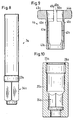
- This snap cuff 4a is shown in FIG. 9 as an individual part.
- the Snap cuff 4a is provided with resilient slats, here it is two lamellae 41a and 42a, which have an organ at their distal end 43a and 44a are connected to compress the slats. Further one recognizes two projections 45a and 46a, which with corresponding Projections 25a and 26a cooperate in the sleeve 20a and the Form snap connection.
- the snap cuff points at the proximal end 4a a connection area 47a, which is provided for this is to be firmly connected to the tool part 3a, for example by Laser welding.
- the tool part 3a itself can be seen in FIG. 8 and also points a non-rotationally symmetrical region 34a, which as in the previous one explained embodiment is designed as a square. Furthermore, the Tool part 3a still a bead-like connection area 37a, which with the connection area 47a of the snap sleeve 4a firmly is connectable, for example, by connecting area 47a to the bead-like connection region 37a firmly connected by laser welding becomes.
- the sleeve 20a can be seen in FIG. 10, which one Has area 24a, which is also non-rotationally symmetrical is, here as a square, which in terms of shape and dimensions considered to match the non-rotationally symmetrical square 34a of the Tool part 3a is designed to receive it in a rotationally fixed manner. Further the sleeve 20a has two projections 25a and 26a at the distal end, which with the projections 45a and 46a of the slats 41a and 42a of the Snap cuff 4a interact and the snap connection form.
- the surgical tool is made up of separately manufactured items such as is composed as follows: First, the snap cuff 4a over the Tool part 3a pushed until the connection area 47a of the snap sleeve 4a over the bead-like connection area 37a of the Tool part 3a comes to rest. Then these two parts are e.g. firmly connected by laser welding. Then it will Tool part 3a inserted into the sleeve 20a until the two projections 45a and 46a of the slats 41a and 42a on the protrusions 25a and 26a Slide and snap the distal end of the sleeve 20a. Then that's it Tool part 3a secured against axial sliding out.
- the two organs 43a and 44a in Pressed towards each other so that the projections 45a and 46a of the Snap sleeve 4a from protrusions 25a and 26a of sleeve 20a be released and at the same time the tool part 3a from the sleeve 20a pulled out.
- the slot 48a between the two as spiral springs trained organs 43a and 44a is designed so that a Overloading the organs 43a and 44a is not possible because the edges 49a and 50a are in contact with excessive pressure forces and thus an overload take up.
- Tool part 3a with the snap cuff attached to it and the handle part 2a with the sleeve 20a can then be cleaned and be sterilized. Then, for example, the same handle part with a completely different type of tool part or the same tool part can be combined with a completely different type of handle.
Landscapes
- Health & Medical Sciences (AREA)
- Engineering & Computer Science (AREA)
- Orthopedic Medicine & Surgery (AREA)
- Surgery (AREA)
- Life Sciences & Earth Sciences (AREA)
- Medical Informatics (AREA)
- Biomedical Technology (AREA)
- Heart & Thoracic Surgery (AREA)
- Nuclear Medicine, Radiotherapy & Molecular Imaging (AREA)
- Molecular Biology (AREA)
- Animal Behavior & Ethology (AREA)
- General Health & Medical Sciences (AREA)
- Public Health (AREA)
- Veterinary Medicine (AREA)
- Mechanical Engineering (AREA)
- Surgical Instruments (AREA)
Abstract
Description
- Fig. 1
- ein erstes Ausführungsbeispiel eines erfindungsgemässen Operationswerkzeugs, bei welchem Griffteil und Werkzeugteil mit Hilfe einer Spann-Manschette fest, aber lösbar, miteinander verbunden sind,
- Fig. 2
- das Ausführungsbeispiel des Operationswerkzeugs aus Fig. 1, wobei jedoch Griffteil und Werkzeugteil noch nicht miteinander verbunden sind,
- Fig. 3
- das Werkzeugteil des Operationswerkzeugs aus Fig. 1 ohne Spann-Manschette,
- Fig. 4
- die Spann-Manschettte des Operationswerkzeugs aus Fig. 1,
- Fig. 5
- die Hülse des Griffteils des Operationswerkzeugs aus Fig. 1
- Fig. 6
- ein zweites Ausführungsbeispiel eines erfindungsgemässen Operationswerkzeugs, wobei das Griffteil und das Werkzeugteil noch nicht miteinander verbunden sind,
- Fig. 7
- das Ausführungsbeispiel des Operationswerkzeugs aus Fig. 6, wobei das Griffteil und das Werkzeugteil mit Hilfe einer Schnapp-Manschette fest, aber lösbar, miteinander verbunden sind,
- Fig. 8
- das Werkzeugteil des Operationswerkzeugs aus Fig. 6 ohne Schnapp-Manschette,
- Fig. 9
- die Schnapp-Manschette des Operationswerkzeugs aus Fig. 6
- Fig. 10
- die Hülse des Griffteils des Operationswerkzeugs aus Fig. 6.
Claims (11)
- Operationswerkzeug (1,1a) für den Einsatz im Operationssaal, welches ein Griffteil (2,2a) umfasst sowie ein mit diesem Griffteil (2,2a) fest verbundenes Werkzeugteil (3,3a), wobei die Verbindung von Griffteil (2,2a) und Werkzeugteil (3,3a) als lösbare Verbindung ausgebildet ist.
- Operationswerkzeug nach Anspruch 1, mit einer Aufnahme am distalen Ende des Griffteils (2,2a), in welche das Werkzeugteil (3,3a) eingebracht wird, wobei am Werkzeugteil und an der Aufnahme Mittel (22,42;25a,26a,45a,46a) vorgesehen sind, welche die feste Verbindung von Griffteil und Werkzeugteil bewirken.
- Operationswerkzeug nach Anspruch 2, bei welchem die Aufnahme für das Werkzeugteil eine aus einem harten, verschleissarmen Material hergestellte Hülse (20a) umfasst, die unlösbar mit dem Griffteil (2a) verbunden ist.
- Operationswerkzeug nach einem der vorangehenden Ansprüche, bei welchem die Verbindung von Griffteil und Werkzeugteil als Schraubverbindung (22,42) ausgebildet ist.
- Operationswerkzeug nach Anspruch 4, bei welchem das Griffteil bzw. die Hülse (20) einen Anschlag (21) für das proximale Ende (30) des Werkzeugteils (3) aufweist, und bei welchem die Schraubverbindung eine Spann-Manschette (4) mit einem Aussengewinde (42) sowie ein mit diesem Aussengewinde (42) der Spann-Manschette (4) zusammenwirkendes Innengewinde (22) im Griffteil bzw. in der Hülse (20) umfasst, wobei die Spann-Manschette (4) das Werkzeugteil (3) umschliesst und in Richtung der Längsachse des Werkzeugteils (3) am Werkzeugteil entlang bewegbar ist, bis Anschlagmittel, die am Werkzeugteil und an der Spann-Manschette (4) vorgesehen sind, aneinander anstossen.
- Operationswerkzeug nach Anspruch 5, bei welchem sowohl der Anschlag (21) im Griffteil bzw. in der Hülse (20) als auch das proximale Ende (30) des Werkzeugteils (3) kreiskegelförmig konisch ausgebildet sind, bei welchem ferner die Spann-Manschette (4) an ihrem proximalen Ende mit dem Aussengewinde (42) versehen ist und an ihrem distalen Ende einen nach innen abstehenden Vorsprung (43) aufweist, der in eine Aussparung (33) aussen auf dem Werkzeugteil (3) hineinragt, sodass er die Bewegung der Spann-Manschette (4) in Richtung der Längsachse des Werkzeugteils (3) begrenzt.
- Operationswerkzeug nach einem der Ansprüche 1 bis 3, bei welchem die Verbindung von Griffteil und Werkzeugteil als Schnappverbindung (25a,26a,45a,46a) ausgebildet ist.
- Operationswerkzeug nach Anspruch 7, bei welchem die Schnappverbindung eine fest mit dem Werkzeugteil (3a) verbundene Schnapp-Manschette (4a) aufweist, welche mit federnden Lamellen (41a,42a) versehen ist, die jeweils einen Vorsprung (45a,46a) aufweisen, der mit einem entsprechenden Vorsprung (25a,26a) am distalen Ende des Griffteils bzw. der Hülse (20a) in Eingriff ist, wobei die Lamellen (41a,42) im weiteren Verlauf in distaler Richtung aus dem Griffteil hervorstehen und ausserhalb des Griffteils mit einem Organ (43a,44a) zum Zusammendrücken der Lamellen (41a,42a) versehen sind, um ein Lösen der miteinander im Eingriff befindlichen Vorsprünge (25a,45a,26a,46a) zu bewirken.
- Operationswerkzeug nach einem der vorangehenden Ansprüche, bei welchem sowohl das Griffteil (2,2a) bzw. die Hülse (20,20a) als auch das Werkzeugteil (3,3a) jeweils einen Bereich (24,34;24a,34a) aufweisen, der nicht-rotationssymmetrisch ausgebildet ist, wobei diese nicht-rotationssymetrisch ausgebildeten Bereiche (24,34;24a,34a) von der Form und von ihren Abmessungen her zueinander passend ausgebildet sind und der nicht-rotationssymmetrische Bereich (24,24a) des Griffteils (2,2a) bzw. der Hülse (20,20a) den entsprechenden nicht-rotationssymetrischen Bereich (34,34a) des Werkzeugteils (3,3a) umschliesst, um ein Drehmoment übertragen zu können.
- Operationswerkzeug nach Anspruch 9, bei welchem der nicht-rotationssymmetrische Bereich (24,34;24a,34a) einen rechteckigen, vorzugsweise quadratischen Querschnitt aufweist.
- Operationswerkzeugsatz, umfassend wenigstens ein Griffteil (2,2a) sowie mehrere Werkzeugteile (3,3a), wobei die Werkzeugteile (3,3a) in ihrem proximalen Bereich so ausgebildet sind, dass unterschiedliche Werkzeugteile (3,3a) von ein- und demselben Griffteil (2,2a) aufgenommen und fest mit diesem verbunden werden können.
Priority Applications (1)
| Application Number | Priority Date | Filing Date | Title |
|---|---|---|---|
| EP20000810999 EP1103227B1 (de) | 1999-11-26 | 2000-10-27 | Operationswerkzeug |
Applications Claiming Priority (3)
| Application Number | Priority Date | Filing Date | Title |
|---|---|---|---|
| EP99811092 | 1999-11-26 | ||
| EP99811092 | 1999-11-26 | ||
| EP20000810999 EP1103227B1 (de) | 1999-11-26 | 2000-10-27 | Operationswerkzeug |
Publications (2)
| Publication Number | Publication Date |
|---|---|
| EP1103227A1 true EP1103227A1 (de) | 2001-05-30 |
| EP1103227B1 EP1103227B1 (de) | 2006-10-11 |
Family
ID=26074060
Family Applications (1)
| Application Number | Title | Priority Date | Filing Date |
|---|---|---|---|
| EP20000810999 Expired - Lifetime EP1103227B1 (de) | 1999-11-26 | 2000-10-27 | Operationswerkzeug |
Country Status (1)
| Country | Link |
|---|---|
| EP (1) | EP1103227B1 (de) |
Citations (4)
| Publication number | Priority date | Publication date | Assignee | Title |
|---|---|---|---|---|
| US1630239A (en) * | 1924-05-09 | 1927-05-24 | Roy S Binkley | Antrum burr |
| US2288584A (en) * | 1940-05-23 | 1942-06-30 | Harry Herschel Leiter | Surgeon's screw driver, screw holder, and stabilizer |
| GB943610A (en) * | 1960-03-09 | 1963-12-04 | Buermoos Dentalwerk | Improvements in dental tools |
| FR2702172A1 (fr) * | 1993-03-05 | 1994-09-09 | Francaise Metallurg | Tournevis muni de logements pour des embouts interchangeables. |
-
2000
- 2000-10-27 EP EP20000810999 patent/EP1103227B1/de not_active Expired - Lifetime
Patent Citations (4)
| Publication number | Priority date | Publication date | Assignee | Title |
|---|---|---|---|---|
| US1630239A (en) * | 1924-05-09 | 1927-05-24 | Roy S Binkley | Antrum burr |
| US2288584A (en) * | 1940-05-23 | 1942-06-30 | Harry Herschel Leiter | Surgeon's screw driver, screw holder, and stabilizer |
| GB943610A (en) * | 1960-03-09 | 1963-12-04 | Buermoos Dentalwerk | Improvements in dental tools |
| FR2702172A1 (fr) * | 1993-03-05 | 1994-09-09 | Francaise Metallurg | Tournevis muni de logements pour des embouts interchangeables. |
Also Published As
| Publication number | Publication date |
|---|---|
| EP1103227B1 (de) | 2006-10-11 |
Similar Documents
| Publication | Publication Date | Title |
|---|---|---|
| DE69415676T2 (de) | Sperrklinken-kompressionseinrichtung | |
| DE69527989T2 (de) | Vorrichtung zur Anbringung von chirurgischen schraubenförmigen Wundklammern | |
| DE102004027881B4 (de) | Knochenschraube und Osteosynthesevorrichtung | |
| DE69623129T2 (de) | Modulare prothese | |
| DE102010016812A1 (de) | Knochenschraube | |
| DE102006010116A1 (de) | Ankerelement zum knotenfreien Fixieren von Gewebe an einem Knochen | |
| DE19841252A1 (de) | Einsetzinstrument für eine Knochenschraube | |
| EP3745971A1 (de) | Polyaxialschraube | |
| DE102004022778B4 (de) | Zahnkeil | |
| WO2019001990A1 (de) | Verlängerungsvorrichtung für einen knochenanker | |
| EP0452792B1 (de) | Knochenchirurgischer Halter | |
| EP2877098B1 (de) | Halter für ein medizinisches, insbesondere chirurgisches instrument | |
| DE3027696C2 (de) | Instrument zur Behandlung von Zahnwurzelkanälen | |
| DE10220190B4 (de) | Chirurgisches Instrument | |
| DE102004026769A1 (de) | Schraube und Werkzeug zum Ein- oder Ausdrehen einer Schraube | |
| DE29805443U1 (de) | Orthopädisches Kompressionsschrauben-Baukastensystem | |
| CH664889A5 (de) | Werkzeug zum einschrauben eines stiftes in einen zahn. | |
| EP3764950B1 (de) | Implantat | |
| DE102011052442B3 (de) | Ratsche und Verfahren zum Übertragen eines Drehmoments auf ein Gegenstück, sowie Verwendung einer derartigen Ratsche im Medizinbereich | |
| EP2196165A1 (de) | Instrument zum Lösen eines Schraubenstumpfes einer Verbindungsschraube eines Zahnimplantats | |
| EP1303219B1 (de) | Medizinisches instrument, insbesondere resektoskop | |
| AT411567B (de) | Bohrer zur herstellung von bohrungen in einem knochengewebe | |
| DE9310668U1 (de) | Schraubendreher | |
| EP1103227A1 (de) | Operationswerkzeug | |
| DE102005016869A1 (de) | Medizinisches Handstück mit einer Spannzange |
Legal Events
| Date | Code | Title | Description |
|---|---|---|---|
| PUAI | Public reference made under article 153(3) epc to a published international application that has entered the european phase |
Free format text: ORIGINAL CODE: 0009012 |
|
| AK | Designated contracting states |
Kind code of ref document: A1 Designated state(s): AT BE CH CY DE DK ES FI FR GB GR IE IT LI LU MC NL PT SE |
|
| AX | Request for extension of the european patent |
Free format text: AL;LT;LV;MK;RO;SI |
|
| 17P | Request for examination filed |
Effective date: 20011102 |
|
| AKX | Designation fees paid |
Free format text: AT BE CH CY DE DK ES FI FR GB GR IE IT LI LU MC NL PT SE |
|
| REG | Reference to a national code |
Ref country code: SE Ref legal event code: TRGR |
|
| 17Q | First examination report despatched |
Effective date: 20050209 |
|
| RAP1 | Party data changed (applicant data changed or rights of an application transferred) |
Owner name: ZIMMER GMBH |
|
| GRAP | Despatch of communication of intention to grant a patent |
Free format text: ORIGINAL CODE: EPIDOSNIGR1 |
|
| GRAS | Grant fee paid |
Free format text: ORIGINAL CODE: EPIDOSNIGR3 |
|
| GRAA | (expected) grant |
Free format text: ORIGINAL CODE: 0009210 |
|
| AK | Designated contracting states |
Kind code of ref document: B1 Designated state(s): AT BE CH CY DE DK ES FI FR GB GR IE IT LI LU MC NL PT SE |
|
| PG25 | Lapsed in a contracting state [announced via postgrant information from national office to epo] |
Ref country code: FI Free format text: LAPSE BECAUSE OF FAILURE TO SUBMIT A TRANSLATION OF THE DESCRIPTION OR TO PAY THE FEE WITHIN THE PRESCRIBED TIME-LIMIT Effective date: 20061011 Ref country code: NL Free format text: LAPSE BECAUSE OF FAILURE TO SUBMIT A TRANSLATION OF THE DESCRIPTION OR TO PAY THE FEE WITHIN THE PRESCRIBED TIME-LIMIT Effective date: 20061011 Ref country code: IE Free format text: LAPSE BECAUSE OF FAILURE TO SUBMIT A TRANSLATION OF THE DESCRIPTION OR TO PAY THE FEE WITHIN THE PRESCRIBED TIME-LIMIT Effective date: 20061011 |
|
| REG | Reference to a national code |
Ref country code: GB Ref legal event code: FG4D Free format text: NOT ENGLISH |
|
| PG25 | Lapsed in a contracting state [announced via postgrant information from national office to epo] |
Ref country code: MC Free format text: LAPSE BECAUSE OF NON-PAYMENT OF DUE FEES Effective date: 20061031 |
|
| REG | Reference to a national code |
Ref country code: CH Ref legal event code: EP Ref country code: CH Ref legal event code: NV Representative=s name: DR. GRAF & PARTNER INTELLECTUAL PROPERTY |
|
| REG | Reference to a national code |
Ref country code: IE Ref legal event code: FG4D Free format text: LANGUAGE OF EP DOCUMENT: GERMAN |
|
| REF | Corresponds to: |
Ref document number: 50013600 Country of ref document: DE Date of ref document: 20061123 Kind code of ref document: P |
|
| PG25 | Lapsed in a contracting state [announced via postgrant information from national office to epo] |
Ref country code: DK Free format text: LAPSE BECAUSE OF FAILURE TO SUBMIT A TRANSLATION OF THE DESCRIPTION OR TO PAY THE FEE WITHIN THE PRESCRIBED TIME-LIMIT Effective date: 20070111 |
|
| PG25 | Lapsed in a contracting state [announced via postgrant information from national office to epo] |
Ref country code: ES Free format text: LAPSE BECAUSE OF FAILURE TO SUBMIT A TRANSLATION OF THE DESCRIPTION OR TO PAY THE FEE WITHIN THE PRESCRIBED TIME-LIMIT Effective date: 20070122 |
|
| PG25 | Lapsed in a contracting state [announced via postgrant information from national office to epo] |
Ref country code: PT Free format text: LAPSE BECAUSE OF FAILURE TO SUBMIT A TRANSLATION OF THE DESCRIPTION OR TO PAY THE FEE WITHIN THE PRESCRIBED TIME-LIMIT Effective date: 20070319 |
|
| ET | Fr: translation filed | ||
| NLV1 | Nl: lapsed or annulled due to failure to fulfill the requirements of art. 29p and 29m of the patents act | ||
| REG | Reference to a national code |
Ref country code: IE Ref legal event code: FD4D |
|
| PLBE | No opposition filed within time limit |
Free format text: ORIGINAL CODE: 0009261 |
|
| STAA | Information on the status of an ep patent application or granted ep patent |
Free format text: STATUS: NO OPPOSITION FILED WITHIN TIME LIMIT |
|
| 26N | No opposition filed |
Effective date: 20070712 |
|
| BERE | Be: lapsed |
Owner name: ZIMMER GMBH Effective date: 20061031 |
|
| PG25 | Lapsed in a contracting state [announced via postgrant information from national office to epo] |
Ref country code: GR Free format text: LAPSE BECAUSE OF FAILURE TO SUBMIT A TRANSLATION OF THE DESCRIPTION OR TO PAY THE FEE WITHIN THE PRESCRIBED TIME-LIMIT Effective date: 20070112 |
|
| PG25 | Lapsed in a contracting state [announced via postgrant information from national office to epo] |
Ref country code: LU Free format text: LAPSE BECAUSE OF NON-PAYMENT OF DUE FEES Effective date: 20061027 |
|
| PG25 | Lapsed in a contracting state [announced via postgrant information from national office to epo] |
Ref country code: CY Free format text: LAPSE BECAUSE OF FAILURE TO SUBMIT A TRANSLATION OF THE DESCRIPTION OR TO PAY THE FEE WITHIN THE PRESCRIBED TIME-LIMIT Effective date: 20061011 |
|
| PGFP | Annual fee paid to national office [announced via postgrant information from national office to epo] |
Ref country code: CH Payment date: 20081015 Year of fee payment: 9 Ref country code: DE Payment date: 20081022 Year of fee payment: 9 |
|
| PGFP | Annual fee paid to national office [announced via postgrant information from national office to epo] |
Ref country code: AT Payment date: 20081015 Year of fee payment: 9 |
|
| PGFP | Annual fee paid to national office [announced via postgrant information from national office to epo] |
Ref country code: SE Payment date: 20081014 Year of fee payment: 9 Ref country code: IT Payment date: 20081025 Year of fee payment: 9 |
|
| PGFP | Annual fee paid to national office [announced via postgrant information from national office to epo] |
Ref country code: FR Payment date: 20081014 Year of fee payment: 9 |
|
| PGFP | Annual fee paid to national office [announced via postgrant information from national office to epo] |
Ref country code: GB Payment date: 20081021 Year of fee payment: 9 |
|
| PG25 | Lapsed in a contracting state [announced via postgrant information from national office to epo] |
Ref country code: BE Free format text: LAPSE BECAUSE OF FAILURE TO SUBMIT A TRANSLATION OF THE DESCRIPTION OR TO PAY THE FEE WITHIN THE PRESCRIBED TIME-LIMIT Effective date: 20061031 |
|
| REG | Reference to a national code |
Ref country code: CH Ref legal event code: PL |
|
| EUG | Se: european patent has lapsed | ||
| REG | Reference to a national code |
Ref country code: FR Ref legal event code: ST Effective date: 20100630 |
|
| PG25 | Lapsed in a contracting state [announced via postgrant information from national office to epo] |
Ref country code: DE Free format text: LAPSE BECAUSE OF NON-PAYMENT OF DUE FEES Effective date: 20100501 Ref country code: FR Free format text: LAPSE BECAUSE OF NON-PAYMENT OF DUE FEES Effective date: 20091102 |
|
| PG25 | Lapsed in a contracting state [announced via postgrant information from national office to epo] |
Ref country code: AT Free format text: LAPSE BECAUSE OF NON-PAYMENT OF DUE FEES Effective date: 20091027 |
|
| PG25 | Lapsed in a contracting state [announced via postgrant information from national office to epo] |
Ref country code: LI Free format text: LAPSE BECAUSE OF NON-PAYMENT OF DUE FEES Effective date: 20091031 Ref country code: CH Free format text: LAPSE BECAUSE OF NON-PAYMENT OF DUE FEES Effective date: 20091031 |
|
| PG25 | Lapsed in a contracting state [announced via postgrant information from national office to epo] |
Ref country code: GB Free format text: LAPSE BECAUSE OF NON-PAYMENT OF DUE FEES Effective date: 20091027 |
|
| PG25 | Lapsed in a contracting state [announced via postgrant information from national office to epo] |
Ref country code: IT Free format text: LAPSE BECAUSE OF NON-PAYMENT OF DUE FEES Effective date: 20091027 |
|
| PG25 | Lapsed in a contracting state [announced via postgrant information from national office to epo] |
Ref country code: SE Free format text: LAPSE BECAUSE OF NON-PAYMENT OF DUE FEES Effective date: 20091028 |