EP1103194A2 - Adjustable protective helmet - Google Patents
Adjustable protective helmet Download PDFInfo
- Publication number
- EP1103194A2 EP1103194A2 EP00403277A EP00403277A EP1103194A2 EP 1103194 A2 EP1103194 A2 EP 1103194A2 EP 00403277 A EP00403277 A EP 00403277A EP 00403277 A EP00403277 A EP 00403277A EP 1103194 A2 EP1103194 A2 EP 1103194A2
- Authority
- EP
- European Patent Office
- Prior art keywords
- protective helmet
- shell
- shell assembly
- adjustable protective
- overlapping portions
- Prior art date
- Legal status (The legal status is an assumption and is not a legal conclusion. Google has not performed a legal analysis and makes no representation as to the accuracy of the status listed.)
- Withdrawn
Links
- 230000001681 protective effect Effects 0.000 title claims abstract description 42
- 230000015572 biosynthetic process Effects 0.000 claims abstract description 15
- 238000005755 formation reaction Methods 0.000 claims abstract description 15
- 230000035939 shock Effects 0.000 claims abstract description 11
- 230000000694 effects Effects 0.000 claims abstract description 8
- 210000003128 head Anatomy 0.000 claims description 24
- 239000006260 foam Substances 0.000 claims description 18
- 210000001061 forehead Anatomy 0.000 claims description 4
- 230000007423 decrease Effects 0.000 claims description 3
- 230000009977 dual effect Effects 0.000 claims description 3
- 239000006261 foam material Substances 0.000 claims description 3
- 238000000926 separation method Methods 0.000 description 12
- 238000010521 absorption reaction Methods 0.000 description 2
- 230000006835 compression Effects 0.000 description 2
- 238000007906 compression Methods 0.000 description 2
- 230000003247 decreasing effect Effects 0.000 description 2
- 230000036961 partial effect Effects 0.000 description 2
- 239000004698 Polyethylene Substances 0.000 description 1
- 238000010276 construction Methods 0.000 description 1
- 230000006378 damage Effects 0.000 description 1
- 238000009499 grossing Methods 0.000 description 1
- 230000000670 limiting effect Effects 0.000 description 1
- 239000000463 material Substances 0.000 description 1
- 238000000034 method Methods 0.000 description 1
- 238000012986 modification Methods 0.000 description 1
- 230000004048 modification Effects 0.000 description 1
- 238000000465 moulding Methods 0.000 description 1
- NJPPVKZQTLUDBO-UHFFFAOYSA-N novaluron Chemical compound C1=C(Cl)C(OC(F)(F)C(OC(F)(F)F)F)=CC=C1NC(=O)NC(=O)C1=C(F)C=CC=C1F NJPPVKZQTLUDBO-UHFFFAOYSA-N 0.000 description 1
- -1 polyethylene Polymers 0.000 description 1
- 229920000573 polyethylene Polymers 0.000 description 1
- 230000002829 reductive effect Effects 0.000 description 1
- 238000009423 ventilation Methods 0.000 description 1
- 125000000391 vinyl group Chemical group [H]C([*])=C([H])[H] 0.000 description 1
- 229920002554 vinyl polymer Polymers 0.000 description 1
Images


Classifications
-
- A—HUMAN NECESSITIES
- A42—HEADWEAR
- A42B—HATS; HEAD COVERINGS
- A42B3/00—Helmets; Helmet covers ; Other protective head coverings
- A42B3/32—Collapsible helmets; Helmets made of separable parts ; Helmets with movable parts, e.g. adjustable
- A42B3/324—Adjustable helmets
Definitions
- the present invention relates to an adjustable protective helmet for sporting activities and more particularly, to an improved adjustable helmet for use by hockey players.
- Protective helmets comprising adjustability features are well known.
- an adjustable helmet having two shell portions that are held together by screws. The loosening and tightening of the screws allow for adjustment of the helmet.
- the two shell portions are fixedly held together, thus are adapted to move relative to one another when the screws are loosened.
- the screws are tightened and the two shell portions are locked in place.
- the two shell portions usually have overlapping surfaces to enable the shell portions to be moved relative to one another while not leaving any gap between the two shell portions.
- Shock-absorbing foam padding is positioned inside the helmet shells to cushion the wearer's head.
- a second drawback of this known configuration of an adjustable helmet is the reduced amount of foam padding at the junction of two padding sections.
- the foam padding sections separation coincides with the shell portions separation.
- This arrangement entails that when the shell portions are spaced apart, a gap is formed between the padding sections in the area where the two shell portions overlap each other. As a result, certain circumstances may leave an area of the cranium with insufficient shock-absorbing foam padding and therefore more limited protection.
- Some helmets have been designed with no padding separation. The necessary gap for adjusting the shell portions is located at the back of the head which may leave the back portion of the cranium with insufficient shock-absorbing foam padding
- the invention provides an adjustable protective helmet for sporting activities comprising a first shell and second shell.
- One of the shells covering the forehead and a portion of the sides of a wearer's head, and the other one of said shells covering the top, back and a portion of the sides of a wearer's head.
- the first and second shells have respective cooperating inner and outer overlapping portions extending transversely across the top portion of the wearer's head for connecting together the shells to form a bowl shaped shell assembly circumscribing the wearer's head.
- the inner overlapping portion is disposed inwardly of the outer overlapping portion and its associated shell; the shells are movable relative to one another in the overlapping portions to provide size adjustability of the helmet.
- the helmet includes a shock absorbing liner inside the shell assembly.
- the shell assembly comprises a ramp defined by a plurality of raised formations on the inside surface of the shell assembly.
- the ramp is positioned next to a free edge of the inner overlapping portion thereby increasing the contact surface area between the liner and the shell assembly in the vicinity of the overlapping portions in order to reduce the risk of a the concentration of forces during impact over the head of the wearer.
- the ramp is located in the central portion of the inside surface of the shell assembly and the raised formations that forms the ramp define a plane which is substantially co-planar with the inside surface of the inner overlapping portion. This arrangement provides an even surface of contact between the liner and the shell assembly in the area around the overlapping portions.
- the raised formations are a series of ribs extending longitudinally from the overlapping portions.
- the series of ribs decreases in height from the overlapping portions to blend with an inner curvature of the shell assembly.
- Figures 1 illustrates an adjustable protective helmet referred to as 20 comprising a back shell 22 and a front shell 24 interlocked together in an overlapping area 25 to form a bowl shaped shell assembly 35 circumscribing the wearer's head.
- Front shell 24 covers the forehead and a portion of the sides of a wearer's head
- back shell 22 covers the top, back and a portion of the sides of a wearer's head.
- Front and back shells 22 and 24 are movable relative to one another as described hereinafter.
- Front shell 24 comprises a top wall portion 40 and a frontal portion 41 that extends into side portions 42 covering the sides of helmet 20.
- back shell 22 comprises a top wall portion 43 and side portions 44.
- Top wall 43 comprises a pair of ridges 28 and 29 extending from the front portion 30 of back shell 22 to the back portion 31 of back shell 22.
- These ridges 28 and 29 are areas of increased geometry adapted to augment the impact absorbing capacity of the protective helmet 20 from shock in the top and back of the wearer's head.
- an area of increased geometry is located on front shell 24 and is formed by recess 33 which gives rise to a pair of ridges 36 and 37 providing added protection to the front portion of the wearer's head.
- Front and back shells 22 and 24 may also feature air vents in recesses 38 to provide adequate ventilation and help cool the wearer's head.
- Front and rear shells 22 and 24 are made of suitable impact resistant material such as polyethylene.
- top wall portion 40 of front shell 24 is located underneath top wall portion 43 of back shell 22 while the side portion 42 of front shell 24 are located over the side portions 44 of back shell 22.
- Front and rear shells 22 and 24 are locked together using screws 45 located on each side of helmet 20 which fasten together side portions 42 and 44.
- Other types of mechanical links may be used as locking means such as for example, a cam and lever assembly combined with a plurality of corresponding teeth on each side portions 42 and 44 which lock together when pressed together by the cam and lever assembly.
- Other means of locking shells 22 and 24 are well known in the art of helmet construction. Front and rear shells 22 and 24 are adapted to move relative to one another when screws 45 are loosened.
- helmet 20 also comprises a shock absorbing liner 19 position inside shell assembly 35.
- Shock absorbing liner 19 is made of a foam material, preferably a vinyl nitryle of a thickness ranging from 10 to 20 mm.
- FIG. 2 illustrates front and rear shells 22 and 24 before they are connected together.
- Back shell 22 comprises a slot 49 while front shell 24 comprises a single aperture 50.
- slot 49 is aligned with aperture 50 and a screw 45 is inserted to tighten shells 22 and 24 together.
- each shell 22 and 24 has an overlapping portion corresponding to the hatched area 46 and 47 defining the overall range of adjustability of helmet 20. Overlapping portions 46 and 47, combined with the slot 49 and aperture 50 arrangement, cooperate to allow relative movement between shells 22 and 24 to provide adjustability of the size of helmet 20.
- front and back shell 22 and 24 are movable relative to one another.
- the dotted lines illustrate helmet 20 in its two extreme positions.
- the distance 52 represents the general range of motion, which also corresponds to overlapping portions 46 and 47 shown in Figure 2.
- Inner overlapping portion 47 is lying inwardly relative to overlapping portion 46 and its associated back shell 22. Both overlapping portions 46 and 47 extend transversely across the top portion of the wearer's head.
- Figure 4 is a frontal view of shell assembly 35 in the closed position.
- FIGS. 5 and 6 are cross sections taken at line 5-5 of Figure 4, it can be seen that the juxtaposition of overlapping portions 46 and 47 creates a step or ridge 55 on the interior surface of shell assembly 35.
- Step 55 is in fact the front lip of overlapping portion 47 protruding inside shell assembly 35.
- the interior curvature of shell assembly 35 is therefor partially broken by overlapping portions 46 and 47 which creates a zone of force concentration during an impact to the head.
- a ramp 60 is added on the interior surface of back shell 22, immediately adjacent overlapping portions 46 and 47 and facing the free edge of inner overlapping portion 47, thereby re-establish the smooth interior curvature of shell assembly 35.
- Ramp 60 is configured to increase the surface area in direct contact between shell assembly 35 and liner 19 in order to reduce the force concentration around step 55 that would result from an impact.
- FIGs 7, 8 and 9 show shell assembly 35 in its wide-open position.
- a gap 57 is opened by the large size adjustment of helmet 20.
- ramp 60 serves as a pedestal which is at the same level or height as step 55 so that liner 19 may at least partially bridge gap 57 along a single plane coinciding with the interior curvature of shell assembly 35 thereby minimizing the force concentration of an impact in this region.
- the inner surface of front shell 24 may also be provided with a ramp 60a to conform its profile to the inner curvature of shell assembly 35.
- ramp 60 is located in the central portion of shell assembly 35 and more specifically adjacent to overlapping portion 46 of rear shell 22 such that the frontal edge of ramp 60 faces the rear edge 61 of front shell 24.
- Ramp 60 is defined by a series of raised formations 62 shaped as longitudinal ribs decreasing in height from overlapping portion 47 to blend with an inner curvature of shell assembly 35.
- the rib arrangement offers a method of increasing the thickness of the shell in ramp 60 area without creating visible sink marks on the outside surface of the shell during the molding of shells 22 and 24.
- An increase in thickness of a specific portion of a molded product usually results in a poor finish of the molded parts.
- the rib arrangement minimizes the increase in thickness while providing the desired profile to reduce the force concentration on impact.
- Figures 12 and 13 illustrate variations of the same theme.
- Ramp 60 is defined by lateral ribs 64, which decrease in height from the first one closest to overlapping portions 46 and 47 to achieve the required profile of the interior curvature of shell assembly 35.
- Ramp 60 is defined by a criss-cross pattern of ribs 66, again of decreasing heights from overlapping portions 46 and 47 to blend with the interior curvature of shell assembly 35.
- the raised formations may be of any configuration as those previously described.
- the pattern of ribs may vary without departing from the spirit of the invention.
- a dual density liner made of a hardback foam and a softer foam may be used.
- the hardback portion of the dual density liner is positioned directly against the interior surface of shell 22 and 24 to provide a strong bridging effect when front and back shells 22 and 24 are separated by a large gap 57 as shown In Figure 8 and 9.
- the hardback portion also helps to present a smooth surface for the softer shock-absorbing foam by smoothing out the irregularities of the interior surface of shells 22 and 24 especially around overlapping portions 46 and 47.
- the hardback foam is located between the shell assembly 35 and the softer foam to reduce the risk of "bottoming out” the foam. Foam "bottoming out” occurs when the compression of the foam during impact reaches a point where further compression would drastically increase the force required. The hardback foam raises this point and by doing so, increase the shock absorbing role of the softer foam during impact.
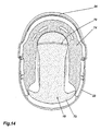
- Figure 14 and 15 illustrate a first pattern of laying out shock absorbing liner 19 inside shell assembly 35.
- Liner 19 is divided into two sections of padding: a first padding section 72, which covers the back portion and the top portion of the wearer's head, and a second padding section 74, which covers the forehead and both sides of the head.
- Padding sections 72 and 74 are separated at the front of helmet 20, in a region that does not coincide with the separation of front and back shells 22 and 24 which is depicted by dotted line 70.
- the separation of padding sections 72 and 74 when shell assembly is adjusted is located in a less critical impact-absorbing zone than at the separation zone 70 where front and back shells 22 and 24 meet and overlap.
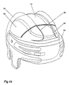
- Figure 15 show that the separation of padding sections 72 and 74 is located in an area of increased geometry formed by front portion of ridges 28 and 29 of front shell 24. This arrangement further minimizes the negative effect of having padding separation caused by the adjustability of helmet 20.
- FIG 16 and 17 illustrates another pattern of shock absorbing liner 19 inside shell assembly 35.
- Liner 19 is divided into five padding sections 80, 82, 84, 86 and 88.
- padding sections 80 and 84 are separated at the front of shell assembly 35, in a region that does not coincide with the separation of front and back shells 22 and 24 which is depicted by dotted line 70.
- padding sections 80 and 88 are separated in an area of increased geometry formed by rear portion of ridges 28 and 29 which minimizes the negative effect of having padding separation.
- the separation of padding section 80 with the side padding sections 82 and 86 is also located directly below ridges 28 and 29.
- the location of each padding sections such that they are separated in areas of front and back shells 22 and 24 which present increased geometry provides a helmet with more efficient impact absorption.
Abstract
Description
- The present invention relates to an adjustable protective helmet for sporting activities and more particularly, to an improved adjustable helmet for use by hockey players.
- Protective helmets comprising adjustability features are well known. In this regard, it is known to provide an adjustable helmet having two shell portions that are held together by screws. The loosening and tightening of the screws allow for adjustment of the helmet. In use, the two shell portions are fixedly held together, thus are adapted to move relative to one another when the screws are loosened. When the desired size is obtained, the screws are tightened and the two shell portions are locked in place. The two shell portions usually have overlapping surfaces to enable the shell portions to be moved relative to one another while not leaving any gap between the two shell portions. Shock-absorbing foam padding is positioned inside the helmet shells to cushion the wearer's head. For practical reasons, there are usually two sections of padding: One section of padding being attached to each shell portion of the protective helmet. This arrangement simplifies the assembly of padding and shell portions and also facilitates assembly of the components.
- An important drawback of this known configuration is that the overlapping surfaces of the two shell portions create a step or ridge on the inner surface of the shell assembly directly above the head of the player. More particularly, in the area of the separation of the two shell portions, the interior curvature of the helmet shell is broken by the feature of adjustability of the helmet. This seems to creates an area of concentration of forces. When an impact occurs, the step or ridge has a tendency to dig into the foam padding and apply a localized force to the head of the wearer, which is highly undesirable in a protective helmet. A protective helmet's main task is to spread the force of impact to as wide a surface as possible without bottoming out, in order to absorb impact and prevent injuries to the cranium.
- A second drawback of this known configuration of an adjustable helmet is the reduced amount of foam padding at the junction of two padding sections. For practical reasons, the foam padding sections separation coincides with the shell portions separation. This arrangement entails that when the shell portions are spaced apart, a gap is formed between the padding sections in the area where the two shell portions overlap each other. As a result, certain circumstances may leave an area of the cranium with insufficient shock-absorbing foam padding and therefore more limited protection. Some helmets have been designed with no padding separation. The necessary gap for adjusting the shell portions is located at the back of the head which may leave the back portion of the cranium with insufficient shock-absorbing foam padding
- It is therefore an object of the invention to provide an adjustable protective helmet having an improved shell assembly, which overcome some of the disadvantages of the prior art.
- It is another object of the invention to provide an adjustable protective helmet, which is adapted to reduce the concentration of force during impact absorption.
- As embodied and broadly described herein, the invention provides an adjustable protective helmet for sporting activities comprising a first shell and second shell. One of the shells covering the forehead and a portion of the sides of a wearer's head, and the other one of said shells covering the top, back and a portion of the sides of a wearer's head. The first and second shells have respective cooperating inner and outer overlapping portions extending transversely across the top portion of the wearer's head for connecting together the shells to form a bowl shaped shell assembly circumscribing the wearer's head. The inner overlapping portion is disposed inwardly of the outer overlapping portion and its associated shell; the shells are movable relative to one another in the overlapping portions to provide size adjustability of the helmet. The helmet includes a shock absorbing liner inside the shell assembly. The shell assembly comprises a ramp defined by a plurality of raised formations on the inside surface of the shell assembly. The ramp is positioned next to a free edge of the inner overlapping portion thereby increasing the contact surface area between the liner and the shell assembly in the vicinity of the overlapping portions in order to reduce the risk of a the concentration of forces during impact over the head of the wearer.
- Advantageously, the ramp is located in the central portion of the inside surface of the shell assembly and the raised formations that forms the ramp define a plane which is substantially co-planar with the inside surface of the inner overlapping portion. This arrangement provides an even surface of contact between the liner and the shell assembly in the area around the overlapping portions.
- Preferably, the raised formations are a series of ribs extending longitudinally from the overlapping portions. The series of ribs decreases in height from the overlapping portions to blend with an inner curvature of the shell assembly.
- Other objects and features of the invention will become apparent by reference to the following description and the drawings.
- A detailed description of the preferred embodiments of the present invention is provided herein below, by way of example only, with reference to the accompanying drawings, in which:
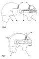
- Figure 1 is a perspective view of an adjustable protective helmet;
- Figure 1A is a perspective view of an adjustable protective helmet with a interior lining:
- Figure 2 is a side elevational view of the two shells making up an adjustable protective helmet;
- Figure 3 is a side elevational view of the two shells making up an adjustable protective helmet with dotted lines showing the relative motion between the shells;
- Figure 4 is a front elevational view of the adjustable protective helmet in the small adjustment position according to an embodiment of the invention;
- Figure 5 is a cross-sectional view taken at line 5-5 of Figure 4 showing the overlapping portions of the adjustable protective helmet in the small adjustment position according to an embodiment of the invention;
- Figure 6 is a partial view of section 5-5 showing details of the shell assembly according to an embodiment of the invention;
- Figure 7 is a front elevational view of the adjustable protective helmet in the large adjustment position according to an embodiment of the invention;
- Figure 8 is a cross-sectional view taken at line 8-8 of Figure 7 showing the overlapping portions of the adjustable protective helmet in the large adjustment position according to an embodiment of the invention;
- Figure 9 is a partial view of section 8-8 showing details of the shell assembly according to an embodiment of the invention;
- Figure 10 is a perspective view of the interior surfaces of the adjustable protective helmet according to an embodiment of the invention;
- Figure 11 is a bottom plan view of the inside of the adjustable protective helmet showing a first embodiment of the raised formations according to the invention;
- Figure 12 is a bottom plan view of the inside of the adjustable protective helmet showing a second embodiment of the raised formations according to the invention;
- Figure 13 is a bottom plan view of the inside of the adjustable protective helmet showing a third embodiment of the raised formations according to the invention;
- Figure 14 is a bottom plan view of the inside of the adjustable protective helmet showing the a first pattern of the liner of shock absorbing padding according to an embodiment of the invention;
- Figure 15 is a side perspective view of the adjustable protective helmet showing the liner pattern of Figure 14 in dotted lines.
- Figure 16 is a bottom plan view of the inside of the adjustable protective helmet showing the a second pattern of the liner of shock absorbing padding according to an embodiment of the invention;
- Figure 17 is a rear perspective view of the adjustable protective helmet showing the liner pattern of Figure 16 in dotted lines.
-
- In the drawings, preferred embodiments of the invention are illustrated by way of examples. It is to be expressly understood that the description and drawings are only for the purpose of illustration and are an aid for understanding. They are not intended to be a definition of the limits of the invention.
- Figures 1 illustrates an adjustable protective helmet referred to as 20 comprising a
back shell 22 and afront shell 24 interlocked together in anoverlapping area 25 to form a bowlshaped shell assembly 35 circumscribing the wearer's head.Front shell 24 covers the forehead and a portion of the sides of a wearer's head, while backshell 22 covers the top, back and a portion of the sides of a wearer's head. Front andback shells -
Front shell 24 comprises atop wall portion 40 and afrontal portion 41 that extends intoside portions 42 covering the sides ofhelmet 20. Similarly,back shell 22 comprises atop wall portion 43 andside portions 44.Top wall 43 comprises a pair ofridges front portion 30 ofback shell 22 to theback portion 31 ofback shell 22. Theseridges protective helmet 20 from shock in the top and back of the wearer's head. Similarly, an area of increased geometry is located onfront shell 24 and is formed byrecess 33 which gives rise to a pair ofridges back shells recesses 38 to provide adequate ventilation and help cool the wearer's head. Front andrear shells - As shown in Figure 1, When front and
back shells top wall portion 40 offront shell 24 is located underneathtop wall portion 43 ofback shell 22 while theside portion 42 offront shell 24 are located over theside portions 44 ofback shell 22. Front andrear shells screws 45 located on each side ofhelmet 20 which fasten togetherside portions side portions shells rear shells screws 45 are tightened and front andrear shells helmet 20 also comprises ashock absorbing liner 19 position insideshell assembly 35.Shock absorbing liner 19 is made of a foam material, preferably a vinyl nitryle of a thickness ranging from 10 to 20 mm. - Figure 2 illustrates front and
rear shells slot 49 whilefront shell 24 comprises asingle aperture 50. When connected together, slot 49 is aligned withaperture 50 and ascrew 45 is inserted to tightenshells shell area helmet 20. Overlappingportions slot 49 andaperture 50 arrangement, cooperate to allow relative movement betweenshells helmet 20. - As shown in Figure 3, front and
back shell helmet 20 in its two extreme positions. Thedistance 52 represents the general range of motion, which also corresponds to overlappingportions portion 47 is lying inwardly relative to overlappingportion 46 and its associated backshell 22. Both overlappingportions - Figure 4 is a frontal view of
shell assembly 35 in the closed position. - Referring to Figures 5 and 6 which are cross sections taken at line 5-5 of Figure 4, it can be seen that the juxtaposition of overlapping
portions ridge 55 on the interior surface ofshell assembly 35.Step 55 is in fact the front lip of overlappingportion 47 protruding insideshell assembly 35. The interior curvature ofshell assembly 35 is therefor partially broken by overlappingportions step 55, aramp 60 is added on the interior surface ofback shell 22, immediately adjacent overlappingportions portion 47, thereby re-establish the smooth interior curvature ofshell assembly 35.Ramp 60 is configured to increase the surface area in direct contact betweenshell assembly 35 andliner 19 in order to reduce the force concentration aroundstep 55 that would result from an impact. - Figures 7, 8 and 9
show shell assembly 35 in its wide-open position. As shown more clearly in Figure 9, agap 57 is opened by the large size adjustment ofhelmet 20. Again, in this position,ramp 60 serves as a pedestal which is at the same level or height asstep 55 so thatliner 19 may at least partially bridgegap 57 along a single plane coinciding with the interior curvature ofshell assembly 35 thereby minimizing the force concentration of an impact in this region. With reference to Figure 6 and 9, the inner surface offront shell 24 may also be provided with aramp 60a to conform its profile to the inner curvature ofshell assembly 35. - As shown in Figures 10 and 11,
ramp 60 is located in the central portion ofshell assembly 35 and more specifically adjacent to overlappingportion 46 ofrear shell 22 such that the frontal edge oframp 60 faces the rear edge 61 offront shell 24.Ramp 60 is defined by a series of raisedformations 62 shaped as longitudinal ribs decreasing in height from overlappingportion 47 to blend with an inner curvature ofshell assembly 35. The rib arrangement offers a method of increasing the thickness of the shell inramp 60 area without creating visible sink marks on the outside surface of the shell during the molding ofshells - Figures 12 and 13 illustrate variations of the same theme. In figure 12,
Ramp 60 is defined bylateral ribs 64, which decrease in height from the first one closest to overlappingportions shell assembly 35. In figure 13,Ramp 60 is defined by a criss-cross pattern ofribs 66, again of decreasing heights from overlappingportions shell assembly 35. Similarly, if aramp 60 is used on the inner surface offront shell 24, the raised formations may be of any configuration as those previously described. The pattern of ribs may vary without departing from the spirit of the invention. - In combination with
ramp 60, a dual density liner made of a hardback foam and a softer foam may be used. The hardback portion of the dual density liner is positioned directly against the interior surface ofshell back shells large gap 57 as shown In Figure 8 and 9. The hardback portion also helps to present a smooth surface for the softer shock-absorbing foam by smoothing out the irregularities of the interior surface ofshells portions shell assembly 35 and the softer foam to reduce the risk of "bottoming out" the foam. Foam "bottoming out" occurs when the compression of the foam during impact reaches a point where further compression would drastically increase the force required. The hardback foam raises this point and by doing so, increase the shock absorbing role of the softer foam during impact. - Figure 14 and 15 illustrate a first pattern of laying out
shock absorbing liner 19 insideshell assembly 35.Liner 19 is divided into two sections of padding: afirst padding section 72, which covers the back portion and the top portion of the wearer's head, and asecond padding section 74, which covers the forehead and both sides of the head. Paddingsections helmet 20, in a region that does not coincide with the separation of front andback shells line 70. In this manner, the separation ofpadding sections separation zone 70 where front andback shells padding sections ridges front shell 24. This arrangement further minimizes the negative effect of having padding separation caused by the adjustability ofhelmet 20. - Figure 16 and 17 illustrates another pattern of
shock absorbing liner 19 insideshell assembly 35.Liner 19 is divided into fivepadding sections padding sections shell assembly 35, in a region that does not coincide with the separation of front andback shells line 70. Furthermore, as is shown in Figure 17,padding sections ridges padding section 80 with theside padding sections ridges back shells - The above description of preferred embodiments should not be interpreted in a limiting manner since other variations, modifications and refinements are possible within the spirit and scope of the present invention. The scope of the invention is defined in the appended claims and their equivalents.
Claims (14)
- An adjustable protective helmet for sporting activities comprising a first shell and second shell, one of said shells covering the forehead and a portion of the sides of a wearer's head, and the other one of said shells covering the top, back and a portion of the sides of a wearer's head; said first and second shells having respective cooperating inner and outer overlapping portions extending transversely across the top portion of the wearer's head for connecting together said shells to form a bowl shaped shell assembly circumscribing the wearer's head; said inner overlapping portion lying inwardly of said outer overlapping portion and its associated shell; said shells movable relative to one another in said overlapping portions to provide size adjustability of said helmet; said helmet including a shock absorbing liner inside said shell assembly; said shell assembly comprising a ramp defined by a plurality of raised formations on the inside surface of said shell assembly, said ramp adjacent and facing a free edge of said inner overlapping portion thereby increasing the contact surface area between said liner and said shell assembly around said overlapping portions in order to reduce the concentration of force of an impact in the vicinity of said overlapping portions.
- An adjustable protective helmet as defined in claim 1 wherein said ramp is located in the central portion of said inside surface of said shell assembly.
- An adjustable protective helmet as defined in claim 2 wherein said raised formations define a plan substantially co-planar with a plan defined by the inside surface of said inner overlapping portion.
- An adjustable protective helmet as defined in claim 3 wherein said raised formations are a series of ribs extending from said overlapping portions.
- An adjustable protective helmet as defined in claim 4 wherein said series of ribs decreases in height from said overlapping portions to blend with an inner curvature of said shell assembly.
- An adjustable protective helmet as defined in claim 3 wherein said raised formations extend longitudinally from said overlapping portions.
- An adjustable protective helmet as defined in claim 6 wherein said raised formations extend substantially perpendicular to said overlapping portions.
- An adjustable protective helmet as defined in claim 4 wherein said ramp is a means for providing a smooth inner curvature of said inside surface of said shell assembly.
- An adjustable protective helmet as defined in claim 3 wherein said ramp defined by a plurality of raised formations laid out in a criss-cross pattern.
- An adjustable protective helmet as defined in claim 1 wherein said liner is made of a foam material.
- An adjustable protective helmet as defined in claim 10 wherein said liner is made of dual density having a hard back foam contacting said shell assembly and a softer foam contacting the wearer's head.
- An adjustable protective helmet as defined in claim 10 wherein said liner comprises a plurality of foam material sections juxtaposed to each other to substantially cover said inside surface of said shell assembly.
- An adjustable protective helmet as defined in claim 12 wherein said sections are juxtaposed to each other in a location ahead of said overlapping portions.
- An adjustable protective helmet as defined in claim 12 wherein said sections are juxtaposed to each other in a location behind of said overlapping portions.
Applications Claiming Priority (2)
| Application Number | Priority Date | Filing Date | Title |
|---|---|---|---|
| CA002290324A CA2290324C (en) | 1999-11-24 | 1999-11-24 | Adjustable protective helmet |
| CA2290324 | 1999-11-24 |
Publications (2)
| Publication Number | Publication Date |
|---|---|
| EP1103194A2 true EP1103194A2 (en) | 2001-05-30 |
| EP1103194A3 EP1103194A3 (en) | 2003-02-05 |
Family
ID=4164703
Family Applications (1)
| Application Number | Title | Priority Date | Filing Date |
|---|---|---|---|
| EP00403277A Withdrawn EP1103194A3 (en) | 1999-11-24 | 2000-11-23 | Adjustable protective helmet |
Country Status (3)
| Country | Link |
|---|---|
| US (1) | US6324700B1 (en) |
| EP (1) | EP1103194A3 (en) |
| CA (1) | CA2290324C (en) |
Cited By (5)
| Publication number | Priority date | Publication date | Assignee | Title |
|---|---|---|---|---|
| WO2005082187A1 (en) * | 2004-01-28 | 2005-09-09 | Pascal Joubert Des Ouches | Semi-rigid protective helmet |
| WO2007059575A1 (en) * | 2005-11-23 | 2007-05-31 | Voz Corp Pty Ltd | A protective helmet |
| US8156569B2 (en) | 2006-10-13 | 2012-04-17 | The University Of British Columbia | Protective helmet with movable outer shell relative to inner shell |
| US9219768B2 (en) | 2011-12-06 | 2015-12-22 | Kenleigh C. Hobby | Virtual presence model |
| US9389677B2 (en) | 2011-10-24 | 2016-07-12 | Kenleigh C. Hobby | Smart helmet |
Families Citing this family (52)
| Publication number | Priority date | Publication date | Assignee | Title |
|---|---|---|---|---|
| CA2321399C (en) * | 2000-09-28 | 2005-07-26 | Bauer Nike Hockey Inc. | Protective helmet with adjustable padding |
| CA2357690C (en) * | 2001-09-25 | 2009-01-20 | Bertrand Racine | Locking device for adjustable helmets |
| CA2365894A1 (en) * | 2001-12-21 | 2003-06-21 | Bauer Nike Hockey Inc. | Sporting helmet having an inflatable bladder with a pump |
| AU2003254000A1 (en) * | 2002-08-08 | 2004-02-25 | Marc S. Schneider | Energy absorbing sports helmet |
| US20110167543A1 (en) * | 2004-05-07 | 2011-07-14 | Enventys, Llc | Adjustable protective apparel |
| CA2573640C (en) | 2004-07-14 | 2010-09-28 | Sport Maska Inc. | Adjustable helmet shell |
| RU2348336C2 (en) * | 2004-07-14 | 2009-03-10 | Спорт Маска Инк. | Adjustable helmet |
| US7870618B2 (en) | 2005-09-30 | 2011-01-18 | Sport Maska Inc. | Adjustment mechanism for a helmet |
| US7634820B2 (en) * | 2006-01-20 | 2009-12-22 | Sport Maska Inc. | Adjustment mechanism for a helmet |
| CA2533493C (en) * | 2006-01-20 | 2009-05-05 | Sport Maska Inc. | Adjustment mechanism for a helmet |
| US8856973B2 (en) * | 2006-10-26 | 2014-10-14 | Sport Maska Inc. | Goalie helmet with novel strap configuration |
| WO2008079525A2 (en) * | 2006-11-03 | 2008-07-03 | Lineweight Llc | Vented ballistic combat helmet |
| US8156574B2 (en) | 2007-05-08 | 2012-04-17 | Warrior Sports, Inc. | Helmet adjustment system |
| US8056150B2 (en) * | 2007-05-08 | 2011-11-15 | Warrior Sports, Inc. | Helmet adjustment system |
| US8296868B2 (en) * | 2007-08-17 | 2012-10-30 | Easton Sports, Inc. | Adjustable hockey helmet |
| US8418270B2 (en) * | 2007-12-12 | 2013-04-16 | Sport Maska Inc. | Protective helmet |
| US7954178B2 (en) * | 2008-08-27 | 2011-06-07 | Bauer Hockey, Inc. | Hockey helmet comprising an occipital adjustment mechanism |
| WO2011025482A1 (en) * | 2009-08-26 | 2011-03-03 | Warrior Sports, Inc. | Adjustable helmet and related method of use |
| US8524338B2 (en) | 2009-11-16 | 2013-09-03 | 9Lives Llc | Impact energy attenuation system |
| US8695122B2 (en) | 2009-12-10 | 2014-04-15 | John Michael DeBoer | Adjustable facial protector |
| US9226539B2 (en) | 2010-07-13 | 2016-01-05 | Sport Maska Inc. | Helmet with rigid shell and adjustable liner |
| US9032558B2 (en) | 2011-05-23 | 2015-05-19 | Lionhead Helmet Intellectual Properties, Lp | Helmet system |
| CA2783079C (en) * | 2011-07-27 | 2016-03-15 | Bauer Hockey Corp. | Adjustable helmet for a hockey or lacrosse player |
| US10306941B2 (en) | 2011-07-27 | 2019-06-04 | Bauer Hockey, Llc | Sports helmet with rotational impact protection |
| US9222758B2 (en) | 2011-08-26 | 2015-12-29 | Velocity Systems, Llc | Versatile protective helmet appliqué assembly |
| USD669226S1 (en) | 2011-11-22 | 2012-10-16 | Warrior Sports, Inc. | Helmet |
| DE112012005354A5 (en) * | 2011-12-19 | 2014-08-28 | Oliver Schimpf | Helmet; Method for reducing or preventing head injury |
| US10149511B2 (en) * | 2012-09-28 | 2018-12-11 | Matscitechno Licensing Company | Protective headgear system |
| US10039335B2 (en) | 2012-11-29 | 2018-08-07 | Bell Sports, Inc. | Multi-component helmet construction |
| US9526291B2 (en) | 2013-06-28 | 2016-12-27 | Sport Maska Inc. | Helmet with rear adjustment mechanism |
| US10477909B2 (en) | 2013-12-19 | 2019-11-19 | Bauer Hockey, Llc | Helmet for impact protection |
| US10993496B2 (en) | 2014-02-21 | 2021-05-04 | Matscitechno Licensing Company | Helmet padding system |
| US11744312B2 (en) | 2014-02-21 | 2023-09-05 | Matscitechno Licensing Company | Helmet padding system |
| US11659882B2 (en) | 2014-02-21 | 2023-05-30 | Matscitechno Licensing Company | Helmet padding system |
| US11253771B2 (en) | 2014-02-21 | 2022-02-22 | Matscitechno Licensing Company | Helmet padding system |
| US11730222B2 (en) | 2014-02-21 | 2023-08-22 | Matscitechno Licensing Company | Helmet padding system |
| US9961952B2 (en) | 2015-08-17 | 2018-05-08 | Bauer Hockey, Llc | Helmet for impact protection |
| CA2942637C (en) | 2015-09-20 | 2023-10-03 | Bauer Hockey Corp. | Helmet |
| US11470907B2 (en) | 2016-03-10 | 2022-10-18 | Sport Maska Inc. | Adjustable helmet with side protective members |
| US10278447B2 (en) * | 2016-03-10 | 2019-05-07 | Sport Maska Inc. | Adjustable helmet with side protective members |
| US10716351B2 (en) * | 2016-06-28 | 2020-07-21 | Peter G. MEADE | Zero impact head gear |
| US10609979B1 (en) | 2017-09-13 | 2020-04-07 | Gerald F. Gallo | Adjustable safety helmet for motorsports |
| EP3539402A1 (en) * | 2018-03-12 | 2019-09-18 | Jörn Steffens | Shock-absorbing liner for a protective helmet and protective helmet comprising said liner |
| CN113423367A (en) | 2018-11-09 | 2021-09-21 | 迪格尼塔纳公司 | Scalp cooling device, method and system |
| USD908970S1 (en) * | 2018-12-07 | 2021-01-26 | Vpg Acquisitionco, Llc | Adjustable helmet |
| US11700903B2 (en) * | 2019-10-07 | 2023-07-18 | Dick's Sporting Goods, Inc. | Adjustable helmet |
| US10869520B1 (en) | 2019-11-07 | 2020-12-22 | Lionhead Helmet Intellectual Properties, Lp | Helmet |
| US11540578B2 (en) | 2020-03-12 | 2023-01-03 | Matscitechno Licensing Company | Helmet system |
| US11540577B2 (en) | 2020-03-12 | 2023-01-03 | Matscitechno Licensing Company | Helmet system |
| CN113432487B (en) * | 2021-05-19 | 2022-11-18 | 清华大学 | Helmet for weakening superposition effect of explosive shock waves in helmet |
| US11547166B1 (en) | 2022-02-11 | 2023-01-10 | Lionhead Helmet Intellectual Properties, Lp | Helmet |
| US11641904B1 (en) | 2022-11-09 | 2023-05-09 | Lionhead Helmet Intellectual Properties, Lp | Helmet |
Citations (6)
| Publication number | Priority date | Publication date | Assignee | Title |
|---|---|---|---|---|
| US3105240A (en) * | 1960-03-25 | 1963-10-01 | Jofa Jonssons Fabriker Aktiebo | Protective helmet |
| US3599239A (en) * | 1969-10-06 | 1971-08-17 | Fiber Metal Products Co The | Protective headgear |
| US3665514A (en) * | 1970-09-22 | 1972-05-30 | Us Army | Low profile size adjustable protective helmet |
| US3820163A (en) * | 1973-05-07 | 1974-06-28 | Cougar Inc | Football helmet having sectional liner of energy absorbing material |
| DE3232762A1 (en) * | 1981-09-14 | 1983-04-28 | CCM Inc., Weston, Ontario | Protective helmet |
| WO1998023174A1 (en) * | 1996-11-29 | 1998-06-04 | Bauer Inc. | Hockey helmet with self-adjusting padding |
Family Cites Families (13)
| Publication number | Priority date | Publication date | Assignee | Title |
|---|---|---|---|---|
| US3579637A (en) | 1969-04-01 | 1971-05-25 | Gentex Corp | Protective helmet of adjustable size |
| US4282610A (en) | 1978-01-16 | 1981-08-11 | The Kendall Company | Protective headgear |
| US4404690A (en) | 1981-08-21 | 1983-09-20 | Amer Sport International Inc. | Hockey helmet |
| SE450620B (en) * | 1982-11-01 | 1987-07-13 | Frosta Fritid Ab | PROTECTIVE HELMET WITH SIZE ADJUSTMENT, SPEC FOR ISHOCKEY AND BANDY PLAYERS |
| IT209878Z2 (en) | 1987-01-30 | 1988-11-04 | Free Helmets S R L | PERFECTED PROTECTION HELMET OF THE MOBILE SECTORS TYPE. |
| DE3727701A1 (en) * | 1987-08-19 | 1989-03-02 | Erb Wilfried | Protective helmet |
| JPH026606A (en) | 1988-06-14 | 1990-01-10 | Michio Arai | Full face type helmet |
| JPH0613216Y2 (en) | 1991-01-29 | 1994-04-06 | 昭栄化工株式会社 | Helmet |
| JP2505726B2 (en) | 1993-10-08 | 1996-06-12 | 昭栄化工株式会社 | Full face type helmet cap body |
| US5628071A (en) | 1995-01-13 | 1997-05-13 | Motorika Ltd. | Collapsible helmet |
| US5511250A (en) | 1995-01-26 | 1996-04-30 | A-Star Sports Group, Inc. | Adjustable protective helmet |
| US6138283A (en) * | 1998-03-10 | 2000-10-31 | Kress; James R. | Protective helmet with medical emergency removal feature |
| US6108824A (en) * | 1998-08-12 | 2000-08-29 | Sport Maska Inc. | Helmet adjustment mechanism with quick release |
-
1999
- 1999-11-24 CA CA002290324A patent/CA2290324C/en not_active Expired - Lifetime
-
2000
- 2000-11-23 EP EP00403277A patent/EP1103194A3/en not_active Withdrawn
- 2000-11-24 US US09/722,095 patent/US6324700B1/en not_active Expired - Lifetime
Patent Citations (6)
| Publication number | Priority date | Publication date | Assignee | Title |
|---|---|---|---|---|
| US3105240A (en) * | 1960-03-25 | 1963-10-01 | Jofa Jonssons Fabriker Aktiebo | Protective helmet |
| US3599239A (en) * | 1969-10-06 | 1971-08-17 | Fiber Metal Products Co The | Protective headgear |
| US3665514A (en) * | 1970-09-22 | 1972-05-30 | Us Army | Low profile size adjustable protective helmet |
| US3820163A (en) * | 1973-05-07 | 1974-06-28 | Cougar Inc | Football helmet having sectional liner of energy absorbing material |
| DE3232762A1 (en) * | 1981-09-14 | 1983-04-28 | CCM Inc., Weston, Ontario | Protective helmet |
| WO1998023174A1 (en) * | 1996-11-29 | 1998-06-04 | Bauer Inc. | Hockey helmet with self-adjusting padding |
Cited By (11)
| Publication number | Priority date | Publication date | Assignee | Title |
|---|---|---|---|---|
| WO2005082187A1 (en) * | 2004-01-28 | 2005-09-09 | Pascal Joubert Des Ouches | Semi-rigid protective helmet |
| WO2007059575A1 (en) * | 2005-11-23 | 2007-05-31 | Voz Corp Pty Ltd | A protective helmet |
| AU2006317514B2 (en) * | 2005-11-23 | 2010-11-25 | VHA Holdings Pty Limited | A protective helmet |
| US8176574B2 (en) | 2005-11-23 | 2012-05-15 | Voz Corp Pty Ltd | Protective helmet |
| AU2011200780B2 (en) * | 2005-11-23 | 2013-08-22 | VHA Holdings Pty Limited | A protective helmet |
| US8156569B2 (en) | 2006-10-13 | 2012-04-17 | The University Of British Columbia | Protective helmet with movable outer shell relative to inner shell |
| US8296863B2 (en) | 2006-10-13 | 2012-10-30 | The University Of British Columbia | Method for a protective helmet with movable outer shell relative to inner shell |
| US9389677B2 (en) | 2011-10-24 | 2016-07-12 | Kenleigh C. Hobby | Smart helmet |
| US10484652B2 (en) | 2011-10-24 | 2019-11-19 | Equisight Llc | Smart headgear |
| US9219768B2 (en) | 2011-12-06 | 2015-12-22 | Kenleigh C. Hobby | Virtual presence model |
| US10158685B1 (en) | 2011-12-06 | 2018-12-18 | Equisight Inc. | Viewing and participating at virtualized locations |
Also Published As
| Publication number | Publication date |
|---|---|
| CA2290324A1 (en) | 2001-05-24 |
| US6324700B1 (en) | 2001-12-04 |
| CA2290324C (en) | 2005-05-24 |
| EP1103194A3 (en) | 2003-02-05 |
Similar Documents
| Publication | Publication Date | Title |
|---|---|---|
| US6324700B1 (en) | Adjustable protective helmet | |
| EP1406519B1 (en) | Protective headgear | |
| CA2321399C (en) | Protective helmet with adjustable padding | |
| EP1506722B1 (en) | Hockey helmet comprising a lateral adjustment mechanism | |
| CA1113712A (en) | Instep protector for safety shoes | |
| EP0942663B1 (en) | Hockey helmet with self-adjusting padding | |
| EP0291308B1 (en) | Safety helmet | |
| US4375108A (en) | Energy-absorbing insert for protective headgear | |
| US6952891B2 (en) | Boot liner | |
| US5231703A (en) | Protective headgear | |
| US5367794A (en) | Cleated shoe protector | |
| EP0966893B1 (en) | Full-face type helmet | |
| EP1388300A2 (en) | Lining for safety helmet and safety helmet having said lining | |
| US20090188022A1 (en) | Hockey helmet with an outer shell made of two different materials | |
| US6161313A (en) | Metatarsal safety guard for footwear | |
| US5647146A (en) | Tongue for internal shoes of ski boots | |
| EP0997080B1 (en) | Full-face type helmet | |
| WO1991005489A1 (en) | Safety helmet and liner therefor | |
| US20020129517A1 (en) | Safety shoe | |
| US20020104174A1 (en) | Safety footwear having metatarsal guard, and methods | |
| EP0107841A1 (en) | Ski boot inner shoe structure | |
| EP0517091B1 (en) | Protective headgear | |
| US5868592A (en) | Swim fin | |
| JP2602810Y2 (en) | Insulator protector made of synthetic resin | |
| CN207136381U (en) | A kind of guard for preventing toe-cap from kicking damage and prevent toe-cap from kicking the shoes of damage |
Legal Events
| Date | Code | Title | Description |
|---|---|---|---|
| PUAI | Public reference made under article 153(3) epc to a published international application that has entered the european phase |
Free format text: ORIGINAL CODE: 0009012 |
|
| AK | Designated contracting states |
Kind code of ref document: A2 Designated state(s): AT BE CH CY DE DK ES FI FR GB GR IE IT LI LU MC NL PT SE TR |
|
| AX | Request for extension of the european patent |
Free format text: AL;LT;LV;MK;RO;SI |
|
| PUAL | Search report despatched |
Free format text: ORIGINAL CODE: 0009013 |
|
| AK | Designated contracting states |
Designated state(s): AT BE CH CY DE DK ES FI FR GB GR IE IT LI LU MC NL PT SE TR |
|
| AX | Request for extension of the european patent |
Extension state: AL LT LV MK RO SI |
|
| RIC1 | Information provided on ipc code assigned before grant |
Ipc: 7A 42B 3/12 B Ipc: 7A 42B 3/06 B Ipc: 7A 42B 3/32 A |
|
| 17P | Request for examination filed |
Effective date: 20030731 |
|
| AKX | Designation fees paid |
Designated state(s): DE FI SE |
|
| STAA | Information on the status of an ep patent application or granted ep patent |
Free format text: STATUS: THE APPLICATION IS DEEMED TO BE WITHDRAWN |
|
| 18D | Application deemed to be withdrawn |
Effective date: 20040602 |