EP1102367A2 - Connector and mould - Google Patents
Connector and mould Download PDFInfo
- Publication number
- EP1102367A2 EP1102367A2 EP00309970A EP00309970A EP1102367A2 EP 1102367 A2 EP1102367 A2 EP 1102367A2 EP 00309970 A EP00309970 A EP 00309970A EP 00309970 A EP00309970 A EP 00309970A EP 1102367 A2 EP1102367 A2 EP 1102367A2
- Authority
- EP
- European Patent Office
- Prior art keywords
- mould
- retainer
- protrusions
- cavities
- retainer insertion
- Prior art date
- Legal status (The legal status is an assumption and is not a legal conclusion. Google has not performed a legal analysis and makes no representation as to the accuracy of the status listed.)
- Withdrawn
Links
- 230000037431 insertion Effects 0.000 claims abstract description 52
- 238000003780 insertion Methods 0.000 claims abstract description 52
- 238000000465 moulding Methods 0.000 claims description 25
- 230000003247 decreasing effect Effects 0.000 abstract 1
- 230000000717 retained effect Effects 0.000 description 7
- 238000005728 strengthening Methods 0.000 description 3
- 238000002347 injection Methods 0.000 description 1
- 239000007924 injection Substances 0.000 description 1
- 230000002452 interceptive effect Effects 0.000 description 1
- 238000004519 manufacturing process Methods 0.000 description 1
- 239000002184 metal Substances 0.000 description 1
- 230000001105 regulatory effect Effects 0.000 description 1
Images



Classifications
-
- H—ELECTRICITY
- H01—ELECTRIC ELEMENTS
- H01R—ELECTRICALLY-CONDUCTIVE CONNECTIONS; STRUCTURAL ASSOCIATIONS OF A PLURALITY OF MUTUALLY-INSULATED ELECTRICAL CONNECTING ELEMENTS; COUPLING DEVICES; CURRENT COLLECTORS
- H01R43/00—Apparatus or processes specially adapted for manufacturing, assembling, maintaining, or repairing of line connectors or current collectors or for joining electric conductors
- H01R43/20—Apparatus or processes specially adapted for manufacturing, assembling, maintaining, or repairing of line connectors or current collectors or for joining electric conductors for assembling or disassembling contact members with insulating base, case or sleeve
- H01R43/24—Assembling by moulding on contact members
Definitions
- the present invention relates to a moulded electrical connector provided with a retainer, and a mould for manufacture of the connector.
- a connector is provided with a side retainer for retaining terminal fittings, whereby the terminal fittings are inserted into a housing and the retainer is pushed in to intersect with these terminal fittings.
- One means of strengthening is to provide two moulds which have protruding moulding members whose protruding length is less than the depth of the retainer attachment hole. These protruding moulding members make mutual contact and thereby form one retainer attachment hole. In this case, the two moulds are removed in mutually opposing directions. Consequently, both ends of the retainer attachment hole are open and pass through to outer faces of the housing. Of these two end openings, the opening at the side from which the retainer is pushed in is then covered by the retainer itself. The other opening is not covered, and the terminal fittings which are within the housing are exposed therefrom. Exposing the terminal fittings from the opening in this manner is unsightly and foreign objects can also easily penetrate therein from the exterior.
- the present invention has taken the above problem into consideration, and aims to present a connector in which the mould is not weakened, and in which the terminal fittings are not exposed.
- a mould for moulding a body of an electrical connector said body having a plurality of parallel terminal insertion cavities, and a retainer insertion cavity intersecting said terminal insertion cavities, said retainer insertion cavity being defined by first and second mould parts extendable towards each other from opposite directions from a disengaged to an engaged condition, the first mould part defining a retainer insertion aperture, a portion of the inner face of the retainer insertion cavity and an inner end wall thereof, and the second mould part defining the remaining portion of the inner face of the retainer insertion cavity and the outer end wall thereof, the first and second mould parts overlapping in the engaged condition.
- Such a mould permits shorter and thus stiffer mould parts which can furthermore support each other due to the overlap.
- the overlap is preferably in the form of an interlock in the direction of the terminal insertion apertures.
- a moulded connector body of an electrical connector said body having a plurality of parallel terminal insertion cavities, and a retainer insertion cavity intersecting said terminal insertion cavities, wherein one end of said retainer insertion cavity is fully open, the other end being partly open, and closed between planes defined by upper and lower edges of said terminal insertion cavities.
- Insertion of a retainer in such a connector body can substantially close the necessary moulding apertures at both ends.
- the retainer is preferably engageable by the body in both temporary and final conditions to permit transport thereof in a partially finished state.
- a connector C consists of a plastic housing 10, a plurality of terminal fittings 19 made from metal (although the present embodiment has four terminal fittings, there may be three or less, or five or more), and a plastic retainer 20.
- Corresponding cavities 11 are formed in a mutually aligned manner within the housing 10, and these cavities 11 open onto anterior and posterior side faces of the housing 10.
- the openings at the posterior side (the right side in Figures 2 and 3) form terminal fitting insertion holes 12 through which the terminal fittings 19 are inserted.
- FIG. 1 Left and right side faces (upper and lower side faces in Figure 2, left and right side faces in Figures 4 to 6) of the housing 10 have openings therein which form a retainer attachment hole 13.
- This retainer attachment hole 13 when seen from a horizontal cross-sectional view, has a long, vertical slit shape.
- the retainer attachment hole 13 extends in a direction which intersects with the insertion path of the terminal fittings 19 within the housing 10.
- a right end of the retainer attachment hole 13 forms an insertion hole 14 which is open along the entire horizontal cross-sectional face of the retainer attachment hole 13.
- the retainer 20 is inserted from this insertion hole 14.
- the upper one third and the lower one third of a left end of the retainer attachment hole 13 form mould removing holes 15. These mould removing holes 15 open out to a left outer side face of the housing 10.
- the central one third of the left end of the retained attachment hole 13 is in a covered state and forms a wall 16.
- a pair of receiving protrusions 17A and 17B are formed on an upper face and on a lower face of the retainer attachment hole 13. These receiving protrusions 17A and 17B are spaced apart from one another in the inserting direction of the retainer 20 in the retainer attachment hole 13 (the left-right direction of the housing 10), and are also separated from one another in the anterior-posterior direction of the housing 10. That is, on the upper face, a receiving protrusion 17A (hereafter referred so as the first receiving protrusion 17A) is located at a left anterior side relative to the inserting direction of the retainer 20, and another receiving protrusion 17B (hereafter referred to as the second receiving protrusion 17B) is located at a right posterior side.
- a receiving protrusion 17A (hereafter referred to as the first receiving protrusion 17A) is located at a right anterior side relative to the inserting direction of the retainer, and another receiving protrusion 17B (hereafter referred to as the second receiving protrusion 17B) is located at a left posterior side.
- the retainer 20 is shaped like a thick plate.
- a pinching member 21 is formed on a base end thereof, and recesses 22 are formed therein in locations which correspond to the cavities 11.
- An upper and lower pair of stopping members 23 are formed on a anterior end (the end opposite the pinching member 21) of the retainer 20. Stopping protrusions 24 are formed on upper and lower faces thereof at locations close to the stopping members 23.
- the retainer 20, which has been inserted into the retained attachment hole 13 from the insertion hole 14, is first maintained in a temporarily retained position.
- the upper and lower stopping members 23 of the retainer 20 rise over the first and second receiving protrusions 17A and 17B of the retainer attachment hole 13 and are retained, in an anterior direction relative to the direction of insertion, by the first receiving protrusions 17A.
- the retainer cannot be moved in the direction of removal.
- the upper and lower stopping members 23 of the retainer 20 engage with the second receiving protrusions 17B of the retainer attachment hole 13, thereby preventing the retainer 20 from moving in the direction of insertion.
- the retainer 20 is temporarily retained in a state whereby its movement is regulated in the direction of removal and the direction of insertion.
- the recessed members 22 correspond in location to the cavities 11. Consequently, the terminal fittings 19 can be inserted into the cavities 11 without interfering with the retainer 20.
- the retainer 20 If the retainer 20 is pushed deeper inwards from this temporarily retained state, it reaches a main retaining position.
- the stopping protrusions 24 rise over the second receiving protrusions 17B and are gripped between the first receiving protrusions 17A and the second receiving protrusions 17B, thereby preventing the retainer 20 from moving in the direction of removal and the direction of insertion.
- a portion of opening edges of the recessed grooves 22 engage with the terminal fittings 19 (this is not shown), thereby locking the terminal fittings 19 in an unremovable state.
- the mould M is formed is formed from: a first mould 30 and a second mould 40, these forming the retainer attachment hole 13; an upper mould 50 and a lower mould 51, these forming the upper face and lower face of the housing 10; and a sliding mould 52 for forming the interior of the cavities 11.
- the first mould 30 has a main moulding member 31 which protrudes so as to enter the retainer attachment hole 13 from the insertion hole 14.
- An outer circumference face of the main moulding member 31 forms an area which joins with the insertion hole 14 at an inner circumference face of the retainer attachment hole 13.
- a protruding member 32 is formed on approximately an upper one third of a protruding end of the main moulding member 31.
- a protruding end face 32A of the protruding member 32 moulds an inner face 16A (the face in the vicinity of the retainer attachment hole 13) of the wall 16.
- Side faces of the protruding member 32 mould the inner side faces of the retainer attachment hole 13.
- An upper and lower of pair of plate-shaped receiving protrusion moulding members 34A and 34B are formed on the protruding end of the main moulding member 31. These receiving protrusion moulding members 34A and 34B are joined to an upper face and a lower face of the main moulding member 31 as unified faces and have spaces 33 between upper and lower faces of the protruding member 32. Protruding end portions of the receiving protrusion moulding members 34A and 34B are step-shaped when seen from above, these steps corresponding to the locations of the first receiving protrusions 17A and the second receiving protrusions 17B. The receiving protrusions moulding 34A and 34B also mould the area from the receiving protrusions 17A and 17B to the insertion hole 14.
- the second mould 40 has an upper and lower pair of receiving protrusion moulding members 41 A and 41B, and has a wall forming face 42 located between these receiving protrusion moulding members 41A and 41B. This moulds an outer face of the wall 16.
- protruding ends of the receiving protrusion moulding members 41A and 41B oppose the protruding ends of the receiving protrusion moulding members 34A and 34B of the first mould 30, leaving spaces 43 therebetween for forming the receiving protrusions 17A and 17B.
- an upper face of the upper receiving protrusion moulding member 41A and a lower face of the lower receiving protruding member 41B mould the area from the receiving protrusions 17A and 17B to the mould removing holes 15, and also mould inner faces of the mould removing holes 15.
- strengthening members 44 protrude from the protruding ends of the receiving protrusion moulding members 41 A and 41B, these fitting with the spaces 33 formed between the receiving protrusion moulding members 34A and 34B and the protruding member 32.
- the moulds 30, 40, 50 and 51 are closed. Then, the strengthening members 44 of the second mould 40 fit into the spaces 33 between the protruding member 32 and the receiving protrusion moulding members 34A and 34B of the first mould 30. Consequently, the protruding ends of the moulds 30 and 40 make close contact and mutually overlap within the retainer attachment hole 13 in a direction which intersects with the removing direction. As a result, there is no danger of change of shape due to injection pressure.
- the spaces 43 for forming the receiving protrusions 17A and 17B are maintained between the anterior ends of the receiving protrusion moulding members 34A and 34B and 41A and 41B (see Figure 9,) and a space 45 for forming the wall 16 is maintained between the protruding end face 32A of the protruding member 32 and the wall forming face 32.
- the connector C is moulded from this state.
- the wall 16 is present on the side opposite the insertion hole 14 of the retainer attachment hole 13. Consequently, the terminal fittings 19 are not exposed at the outer face of the housing 10. Moreover, a decrease in the strength of the moulds 30 and 40 is avoided when the connector C is to be moulded by ensuring that the anterior ends of the first mould 30 (which is removed from the housing 10 via the insertion hole 14) and the second mould 30 (which is removed via the mould removing holes 15) fit together in a doubled-over manner in a direction which intersects with the direction of mould removal. That is, the moulds 30 and 40 are strengthened even though the wall 16 opposite the insertion hole 14 of the retainer attachment hole 13 is present.
Landscapes
- Engineering & Computer Science (AREA)
- Manufacturing & Machinery (AREA)
- Connector Housings Or Holding Contact Members (AREA)
- Moulds For Moulding Plastics Or The Like (AREA)
- Manufacturing Of Electrical Connectors (AREA)
Abstract
Portions of a side of a retainer attachment hole 13, which are opposite an insertion hole
14 for a retainer 20, are open to form mould removing holes 15, the remaining portion
being covered by a wall 16. This wall 16 reduces the degree to which terminal fittings
19 are exposed from the interior of a housing 10. When a connector C is to be
moulded, anterior ends of a first mould 30 (which is removed from the housing 10 via
the insertion hole 14) and a second mould 40 (which is removed via the mould
removing holes 15) fit together within the retainer attachment hole 13 in a doubled-over
manner in a direction which intersects with the direction of mould removal.
Consequently, the strength of the moulds 30 and 40 is not decreased.
Description
- The present invention relates to a moulded electrical connector provided with a retainer, and a mould for manufacture of the connector.
- A connector is provided with a side retainer for retaining terminal fittings, whereby the terminal fittings are inserted into a housing and the retainer is pushed in to intersect with these terminal fittings.
- This type of connector is described in JP 62-136781 and JP 1-197979.
- In this connector, if an attachment hole for the retainer is long and narrow or plate-shaped, a mould for forming this retainer attachment hole is also long and narrow or plate-shaped and may be relatively weak. Consequently, measures to strengthen it are required.
- One means of strengthening is to provide two moulds which have protruding moulding members whose protruding length is less than the depth of the retainer attachment hole. These protruding moulding members make mutual contact and thereby form one retainer attachment hole. In this case, the two moulds are removed in mutually opposing directions. Consequently, both ends of the retainer attachment hole are open and pass through to outer faces of the housing. Of these two end openings, the opening at the side from which the retainer is pushed in is then covered by the retainer itself. The other opening is not covered, and the terminal fittings which are within the housing are exposed therefrom. Exposing the terminal fittings from the opening in this manner is unsightly and foreign objects can also easily penetrate therein from the exterior.
- The present invention has taken the above problem into consideration, and aims to present a connector in which the mould is not weakened, and in which the terminal fittings are not exposed.
- According to one aspect of the invention there is provided a mould for moulding a body of an electrical connector, said body having a plurality of parallel terminal insertion cavities, and a retainer insertion cavity intersecting said terminal insertion cavities, said retainer insertion cavity being defined by first and second mould parts extendable towards each other from opposite directions from a disengaged to an engaged condition, the first mould part defining a retainer insertion aperture, a portion of the inner face of the retainer insertion cavity and an inner end wall thereof, and the second mould part defining the remaining portion of the inner face of the retainer insertion cavity and the outer end wall thereof, the first and second mould parts overlapping in the engaged condition.
- Such a mould permits shorter and thus stiffer mould parts which can furthermore support each other due to the overlap. The overlap is preferably in the form of an interlock in the direction of the terminal insertion apertures.
- According to a second aspect of the invention there is provided a moulded connector body of an electrical connector, said body having a plurality of parallel terminal insertion cavities, and a retainer insertion cavity intersecting said terminal insertion cavities, wherein one end of said retainer insertion cavity is fully open, the other end being partly open, and closed between planes defined by upper and lower edges of said terminal insertion cavities.
- Insertion of a retainer in such a connector body can substantially close the necessary moulding apertures at both ends. The retainer is preferably engageable by the body in both temporary and final conditions to permit transport thereof in a partially finished state.
- Other features of the invention are disclosed in the following description of a preferred embodiment shown by way of example only in the accompanying drawings in which:
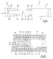
- Figure 1 is a diagonal view of an embodiment of the invention showing a retainer in a separated state from a housing;
- Figure 2 is a horizontal cross-sectional view of the housing;
- Figure 3 is a vertical cross-sectional view of the housing;
- Figure 4 is a side cross-sectional view of the housing;
- Figure 5 is a side cross-sectional view of the retainer in a temporarily retained state in the housing;
- Figure 6 is a side cross-sectional view of the retainer in a main retaining state in the housing;
- Figure 7 is a diagonal view of a mould;
- Figure 8 is a side face view of the mould in an open state;
- Figure 9 is a partially cut-away side face view of the mould in a closed state;
- Figure 10 is a plan view of the mould in the open state;
- Figure 11 is a partially cut-away plan view of the mould in the closed state.
-
- An embodiment of the present invention is described below with the aid of Figures 1 to 11.
- A connector C consists of a
plastic housing 10, a plurality ofterminal fittings 19 made from metal (although the present embodiment has four terminal fittings, there may be three or less, or five or more), and aplastic retainer 20. Correspondingcavities 11 are formed in a mutually aligned manner within thehousing 10, and thesecavities 11 open onto anterior and posterior side faces of thehousing 10. The openings at the posterior side (the right side in Figures 2 and 3) form terminalfitting insertion holes 12 through which theterminal fittings 19 are inserted. - Left and right side faces (upper and lower side faces in Figure 2, left and right side faces in Figures 4 to 6) of the
housing 10 have openings therein which form aretainer attachment hole 13. Thisretainer attachment hole 13, when seen from a horizontal cross-sectional view, has a long, vertical slit shape. Theretainer attachment hole 13 extends in a direction which intersects with the insertion path of theterminal fittings 19 within thehousing 10. A right end of theretainer attachment hole 13 forms aninsertion hole 14 which is open along the entire horizontal cross-sectional face of theretainer attachment hole 13. Theretainer 20 is inserted from thisinsertion hole 14. The upper one third and the lower one third of a left end of theretainer attachment hole 13 formmould removing holes 15. Thesemould removing holes 15 open out to a left outer side face of thehousing 10. The central one third of the left end of the retainedattachment hole 13 is in a covered state and forms awall 16. - A pair of receiving
protrusions retainer attachment hole 13. These receivingprotrusions retainer 20 in the retainer attachment hole 13 (the left-right direction of the housing 10), and are also separated from one another in the anterior-posterior direction of thehousing 10. That is, on the upper face, a receivingprotrusion 17A (hereafter referred so as the first receivingprotrusion 17A) is located at a left anterior side relative to the inserting direction of theretainer 20, and another receivingprotrusion 17B (hereafter referred to as the second receivingprotrusion 17B) is located at a right posterior side. On the lower face, a receivingprotrusion 17A (hereafter referred to as the first receivingprotrusion 17A) is located at a right anterior side relative to the inserting direction of the retainer, and another receivingprotrusion 17B (hereafter referred to as the second receivingprotrusion 17B) is located at a left posterior side. - The
retainer 20 is shaped like a thick plate. Apinching member 21 is formed on a base end thereof, andrecesses 22 are formed therein in locations which correspond to thecavities 11. An upper and lower pair of stoppingmembers 23 are formed on a anterior end (the end opposite the pinching member 21) of theretainer 20. Stoppingprotrusions 24 are formed on upper and lower faces thereof at locations close to the stoppingmembers 23. - The
retainer 20, which has been inserted into the retainedattachment hole 13 from theinsertion hole 14, is first maintained in a temporarily retained position. In this state, as shown in Figure 5, the upper andlower stopping members 23 of theretainer 20 rise over the first and second receivingprotrusions retainer attachment hole 13 and are retained, in an anterior direction relative to the direction of insertion, by the first receivingprotrusions 17A. By this means, the retainer cannot be moved in the direction of removal. Furthermore, the upper and lower stoppingmembers 23 of theretainer 20 engage with the second receivingprotrusions 17B of theretainer attachment hole 13, thereby preventing theretainer 20 from moving in the direction of insertion. That is, theretainer 20 is temporarily retained in a state whereby its movement is regulated in the direction of removal and the direction of insertion. In this state, therecessed members 22 correspond in location to thecavities 11. Consequently, theterminal fittings 19 can be inserted into thecavities 11 without interfering with theretainer 20. - If the
retainer 20 is pushed deeper inwards from this temporarily retained state, it reaches a main retaining position. In this state, as shown in Figure 6, the stoppingprotrusions 24 rise over the second receivingprotrusions 17B and are gripped between the first receivingprotrusions 17A and the second receivingprotrusions 17B, thereby preventing theretainer 20 from moving in the direction of removal and the direction of insertion. In this state, a portion of opening edges of the recessedgrooves 22 engage with the terminal fittings 19 (this is not shown), thereby locking theterminal fittings 19 in an unremovable state. - Next, a mould M for forming the connector C is explained with the aid of Figures 7 to 11.
- The mould M is formed is formed from: a
first mould 30 and asecond mould 40, these forming theretainer attachment hole 13; anupper mould 50 and alower mould 51, these forming the upper face and lower face of thehousing 10; and a slidingmould 52 for forming the interior of thecavities 11. - The
first mould 30 has amain moulding member 31 which protrudes so as to enter theretainer attachment hole 13 from theinsertion hole 14. An outer circumference face of themain moulding member 31 forms an area which joins with theinsertion hole 14 at an inner circumference face of theretainer attachment hole 13. Further, a protrudingmember 32 is formed on approximately an upper one third of a protruding end of themain moulding member 31. Aprotruding end face 32A of the protrudingmember 32 moulds aninner face 16A (the face in the vicinity of the retainer attachment hole 13) of thewall 16. Side faces of the protrudingmember 32 mould the inner side faces of theretainer attachment hole 13. An upper and lower of pair of plate-shaped receivingprotrusion moulding members main moulding member 31. These receivingprotrusion moulding members main moulding member 31 as unified faces and havespaces 33 between upper and lower faces of the protrudingmember 32. Protruding end portions of the receivingprotrusion moulding members protrusions 17A and the second receivingprotrusions 17B. The receiving protrusions moulding 34A and 34B also mould the area from the receivingprotrusions insertion hole 14. - The
second mould 40 has an upper and lower pair of receivingprotrusion moulding members wall forming face 42 located between these receivingprotrusion moulding members wall 16. When the mould is in a closed state, protruding ends of the receivingprotrusion moulding members protrusion moulding members first mould 30, leavingspaces 43 therebetween for forming the receivingprotrusions protrusion moulding member 41A and a lower face of the lowerreceiving protruding member 41B mould the area from the receivingprotrusions mould removing holes 15, and also mould inner faces of the mould removing holes 15. Moreover, strengtheningmembers 44 protrude from the protruding ends of the receivingprotrusion moulding members spaces 33 formed between the receivingprotrusion moulding members member 32. - When the connector C is to be moulded, the
moulds members 44 of thesecond mould 40 fit into thespaces 33 between the protrudingmember 32 and the receivingprotrusion moulding members first mould 30. Consequently, the protruding ends of themoulds retainer attachment hole 13 in a direction which intersects with the removing direction. As a result, there is no danger of change of shape due to injection pressure. - When the mould is in the closed state, the
spaces 43 for forming the receivingprotrusions protrusion moulding members space 45 for forming thewall 16 is maintained between theprotruding end face 32A of the protrudingmember 32 and thewall forming face 32. The connector C is moulded from this state. When the mould is to be opened after moulding has been completed. thefirst mould 30 is removed to the right of thehousing 10 from theinsertion hole 14 of theretainer attachment hole 13, and the receivingprotrusion moulding members second mould 40 are removed by being pulled from themould removing holes 15 at the upper and lower portions of thewall 16. - In the present embodiment, the
wall 16 is present on the side opposite theinsertion hole 14 of theretainer attachment hole 13. Consequently, theterminal fittings 19 are not exposed at the outer face of thehousing 10. Moreover, a decrease in the strength of themoulds housing 10 via the insertion hole 14) and the second mould 30 (which is removed via the mould removing holes 15) fit together in a doubled-over manner in a direction which intersects with the direction of mould removal. That is, themoulds wall 16 opposite theinsertion hole 14 of theretainer attachment hole 13 is present.
Claims (10)
- A mould for moulding a body of an electrical connector, said body having a plurality of parallel terminal insertion cavities, and a retainer insertion cavity intersecting said terminal insertion cavities, said retainer insertion cavity being defined by first and second mould parts (30,40) extendable towards each other from opposite directions from a disengaged to an engaged condition, the first mould part (30) defining a retainer insertion aperture, a portion of the inner face of the retainer insertion cavity and the inner face (16A) of an end wall thereof, and the second mould part (40) defining the remaining portion of the inner face of the retainer insertion cavity and the outer face (16B) of the end wall thereof, the first and second mould parts (30,40) overlapping in the engaged condition.
- A mould according to claim 1 wherein said first mould part (30) comprises an elongate member (31), and said second mould part (40) comprises two spaced elongate members (41A, 41B), a wall (42) between said spaced elongate members defining said outer face (16B) of the end wall.
- A mould according to claim 1 or claim 2 wherein said first and second mould parts (30,40) overlap in the plane perpendicular to the direction of said retainer insertion cavity.
- A mould according to any preceding claim wherein said first and second mould parts (30,40) overlap in the plane perpendicular to the direction of said terminal insertion cavities.
- A mould according to claim 4 wherein said first and second mould parts (30,40) define inwardly directed protrusions of said retainer insertion cavity, said protrusions extending in the plane perpendicular to said terminal insertion cavities.
- A mould according to claim 5 and defining two of said protrusions at a spacing in the direction of said retainer insertion cavity.
- A mould according to claim 6, and defining two facing pairs of said protrusions.
- A moulded connector body of an electrical connector, said body having a plurality of parallel terminal insertion cavities (12), and a retainer insertion cavity (13) intersecting said terminal insertion cavities (12), wherein one end (14) of said retainer insertion cavity is fully open to the exterior, the other end (15,16) being partly open to the exterior, and closed between planes defined by upper and lower edges of said terminal insertion cavities, and an end wall defined by an inner face (16A) and outer face (16B).
- A connector body according to claim 8 and having two protrusions (17A, 17B) extending into said retainer insertion cavity (13) from one side thereof, said protrusions (17A, 17B) being spaced in the direction of the retainer insertion cavity (13) and not overlapping in the direction of said terminal insertion apertures (12).
- A connector body according to claim 9 and having two pairs of said protrusions (17A, 17B) extending towards each other from opposite sides.
Applications Claiming Priority (2)
| Application Number | Priority Date | Filing Date | Title |
|---|---|---|---|
| JP32709599A JP2001143806A (en) | 1999-11-17 | 1999-11-17 | Connector and mold equipment |
| JP32709599 | 1999-11-17 |
Publications (1)
| Publication Number | Publication Date |
|---|---|
| EP1102367A2 true EP1102367A2 (en) | 2001-05-23 |
Family
ID=18195246
Family Applications (1)
| Application Number | Title | Priority Date | Filing Date |
|---|---|---|---|
| EP00309970A Withdrawn EP1102367A2 (en) | 1999-11-17 | 2000-11-09 | Connector and mould |
Country Status (3)
| Country | Link |
|---|---|
| US (1) | US6435919B1 (en) |
| EP (1) | EP1102367A2 (en) |
| JP (1) | JP2001143806A (en) |
Families Citing this family (9)
| Publication number | Priority date | Publication date | Assignee | Title |
|---|---|---|---|---|
| JP3806924B2 (en) * | 2001-11-22 | 2006-08-09 | 住友電装株式会社 | connector |
| US6878018B2 (en) * | 2003-01-02 | 2005-04-12 | Yazaki Corporation | Electrical connector |
| US6881102B2 (en) * | 2003-06-13 | 2005-04-19 | Tyco Electronics Corporation | Terminal locking mechanism for hybrid electrical connector |
| JP3994931B2 (en) * | 2003-06-13 | 2007-10-24 | 住友電装株式会社 | connector |
| JP4316451B2 (en) * | 2004-09-02 | 2009-08-19 | 株式会社東海理化電機製作所 | connector |
| US7179136B1 (en) * | 2006-09-19 | 2007-02-20 | Delphi Technologies, Inc. | Electrical connector |
| JP5327547B2 (en) * | 2010-01-22 | 2013-10-30 | 住友電装株式会社 | connector |
| JP7389407B2 (en) * | 2020-03-09 | 2023-11-30 | 株式会社オートネットワーク技術研究所 | card edge connector |
| US12658628B2 (en) * | 2023-06-12 | 2026-06-16 | Te Connectivity Solutions Gmbh | Terminal positioning device |
Family Cites Families (4)
| Publication number | Priority date | Publication date | Assignee | Title |
|---|---|---|---|---|
| US4867771A (en) * | 1984-07-13 | 1989-09-19 | Bha Group, Inc. | Tensioning device for bag filters |
| JPS62136781A (en) * | 1985-12-10 | 1987-06-19 | 日産自動車株式会社 | Structure for fixing terminals to connector housing |
| JPH01197979A (en) | 1988-01-31 | 1989-08-09 | Amp Inc | Double-lock connector |
| JPH09320672A (en) * | 1996-05-29 | 1997-12-12 | Yazaki Corp | connector |
-
1999
- 1999-11-17 JP JP32709599A patent/JP2001143806A/en active Pending
-
2000
- 2000-11-09 EP EP00309970A patent/EP1102367A2/en not_active Withdrawn
- 2000-11-16 US US09/713,208 patent/US6435919B1/en not_active Expired - Fee Related
Also Published As
| Publication number | Publication date |
|---|---|
| US6435919B1 (en) | 2002-08-20 |
| JP2001143806A (en) | 2001-05-25 |
Similar Documents
| Publication | Publication Date | Title |
|---|---|---|
| US6443760B2 (en) | Connector | |
| CN101345385B (en) | A connector and assembling method thereof | |
| US6599153B2 (en) | Connector with incorrect fitting prevention means | |
| US6361378B1 (en) | Connector with a side retainer | |
| US5743761A (en) | Electrical connector | |
| JPH0773923A (en) | Connector with terminal locking device | |
| US6435919B1 (en) | Connector and mould | |
| EP0978905B1 (en) | Connector | |
| JPH04137474A (en) | Double lock type electric connector | |
| EP1049214A1 (en) | Connector | |
| JP3175575B2 (en) | connector | |
| JP3317390B2 (en) | connector | |
| US7628649B2 (en) | Connector | |
| EP1416593B1 (en) | A connector | |
| JP3710957B2 (en) | Connector and method of assembling the connector | |
| EP0884805A2 (en) | Connector and method for manufacturing the same | |
| EP1220365B1 (en) | Divided connector | |
| US6835105B1 (en) | Connector and method of connecting a connector with a mating connector | |
| JP3858641B2 (en) | connector | |
| JP4096512B2 (en) | connector | |
| CN100527531C (en) | Connector, a method of molding it and a mold therefor | |
| JP4240855B2 (en) | connector | |
| JPH11307164A (en) | Connector with retainer | |
| US20240162650A1 (en) | Connector with a coupling element having two protuberances | |
| JPH08148243A (en) | Joint connector |
Legal Events
| Date | Code | Title | Description |
|---|---|---|---|
| PUAI | Public reference made under article 153(3) epc to a published international application that has entered the european phase |
Free format text: ORIGINAL CODE: 0009012 |
|
| 17P | Request for examination filed |
Effective date: 20001124 |
|
| AK | Designated contracting states |
Kind code of ref document: A2 Designated state(s): AT BE CH CY DE DK ES FI FR GB GR IE IT LI LU MC NL PT SE TR |
|
| AX | Request for extension of the european patent |
Free format text: AL;LT;LV;MK;RO;SI |
|
| STAA | Information on the status of an ep patent application or granted ep patent |
Free format text: STATUS: THE APPLICATION HAS BEEN WITHDRAWN |
|
| 18W | Application withdrawn |
Withdrawal date: 20011212 |