-
The present invention relates to a black filler for
magnetic recording medium and a magnetic recording medium
using the black filler. More particularly, the present
invention relates to a black filler exhibiting not only an
excellent dispersibility in vehicle due to less amount of
carbon black desorbed or fallen-off from the surface thereof,
but also a more excellent blackness, a lower volume
resistivity value and a well-controlled myristic acid
adsorption and a magnetic recording medium exhibiting not
only an excellent durability, a good electromagnetic
performance, an excellent surface smoothness, a smaller
light transmittance and a lower surface electrical
resistivity value, but also a small friction coefficient and
an excellent running durability.
-
With recent tendencies of miniaturization and weight
reduction of video or audio magnetic recording and
reproducing apparatuses as well as long-time recording by
these apparatuses, magnetic recording media such as magnetic
tapes or magnetic discs have been strongly required to have
a high performance, namely high recording density, high
durability, good electromagnetic performance or the like.
-
The magnetic recording media such as magnetic tapes or
magnetic discs are contacted with a magnetic head upon
recording and reproduction, so that a magnetic recording
layer thereof tends to be abraded, resulting in
contamination of the magnetic head as well as deterioration
in recording and reproducing characteristics thereof. For
this reason, it has been conventionally demanded to provide
high-durability magnetic recording media having a high
abrasion resistance.
-
Hitherto, in order to enhance an abrasion resistance of
the magnetic recording layer of magnetic recording media, it
has been attempted to incorporate various fillers such as
alumina (Al2O3), hematite (α-Fe2O3) and dichromium trioxide
(Cr2O3) into the magnetic recording layer.
-
For instance, as magnetic recording media using alumina
(Al2O3), there have been proposed magnetic recording media in
which α-Al2O3 particles containing an amorphous phase are
used as a filler (Japanese Patent Application Laid-Open
(KOKAI) No. 5-36059(1993)), magnetic recording media in
which α-Al2O3 particles having a specific crystal structure
are used as a filler (Japanese Patent Application Laid-Open
(KOKAI) No. 7-244836(1995)) and the like; as magnetic
recording media using hematite (α-Fe2O3), there have been proposed magnetic recording media in which granular α-Fe2O3
particles are used as a filler (Japanese Patent Application
Laid-Open (KOKAI) No. 61-194628(1986)), magnetic recording
media in which liquid hydrocarbon and α-Fe2O3 particles are
used (Japanese Patent Application Laid-Open (KOKAI) No. 54-70806(1979))
and the like; and as magnetic recording media
using dichromium trioxide (Cr2O3), there have been proposed
magnetic recording media in which acicular Cr2O3 particles
are used as a filler (Japanese Patent Application Laid-Open
(KOKAI) No. 62-112221(1987)) and the like.
-
Specifically, the magnetic recording medium described
in Japanese Patent Application Laid-Open (KOKAI) No. 61-194628(1986)
contains magnetic particles having a specific
surface area of not less than about 28 m2/g and granular α-Fe2O3
having an average particle diameter of about 0.05 to 1
um. This magnetic recording medium is produced by
dispersing a mixture composed of 300 parts by weight of Co-coated
γ-Fe2O3, 38 parts by weight of vinyl chloride-vinyl
acetate copolymer, 24 parts by weight of polyurethane resin,
7 parts by weight of stearic acid, one part by weight of
silicone oil, a prescribed amount of granular α-Fe2O3 having
a predetermined particle size and 800 parts by weight of a
mixed solvent containing methyl ethyl ketone and toluene in
equal amounts, for 40 minutes using a ball mill to prepare a
magnetic coating composition, and then coating a base film
with the magnetic coating composition.
-
However, these fillers have respective inherent
problems. Namely, it is known that alumina shows a poor
dispersibility in binder resin. With increase in amount of
alumina added, the obtained magnetic recording medium is
considerably deteriorated in electromagnetic performance.
Hematite particles exhibit a relatively good dispersibility
in binder resin. However, in order to obtain magnetic
recording media having a sufficient durability, it is
required to add a considerably large amount of the hematite
particles thereto, resulting in deteriorated filling
percentage of magnetic particles and, therefore, poor
electromagnetic performance. Further, the use of dichromium
trioxide is unfavorable from environmental and hygienic
viewpoints.
-
It is also known that when the amount of these fillers
added to the magnetic layer is increased, resultant magnetic
recording media are improved in durability, but deteriorated
in dispersibility of magnetic particles in vehicle, thereby
causing a considerable deterioration in electromagnetic
performance thereof.
-
Accordingly, it has been strongly demanded to provide
magnetic recording media containing such a filler which does
not adversely affect the dispersibility of magnetic
particles in vehicle even when the filler is added in an
amount sufficient to impart a high durability thereto,
thereby preventing the magnetic recording media from being
deteriorated in electromagnetic performance thereof.
-
In current general-purpose video tape systems, the end
position of such a magnetic tape is recognized by detecting
a transparent leader tape provided at the tape end thereof
using a sensor.
-
However, with recent demands for high-density recording
on magnetic recording media, the particle size of magnetic
particles used therein becomes much finer, so that a
magnetic recording layer containing such magnetic particles
has a high light transmittance. As a result, there arises
the risk of occurrence of errors upon detecting the end
position of the magnetic tape. Therefore, it has been
strongly required that a magnetic recording portion of the
magnetic tape has a sufficiently high blackness, i.e., a low
light transmittance.
-
Further, it has been demanded to further improve
characteristics of magnetic recording media. That is, it is
strongly required to provide magnetic recording media having
not only the above-described characteristics but also a
small surface electrical resistivity, an improved running
property and the like.
-
When the surface electrical resistivity of magnetic
recording media is large, the amount of electrostatic charge
thereon is increased, so that cut chips of the magnetic
recording media or dusts are adhered onto the surfaces of
the magnetic recording media upon production and use thereof,
thereby causing problems such as increase in drop-outs.
-
Magnetic recording media have been continuously
required to enhance performances thereof. In particular, it
has been strongly required to improve physical properties of
these magnetic recording media such as running property in
addition to the above-described high-density recording
property.
-
The running property of magnetic recording media
(tapes) can be ensured by adding a fatty acid such as
myristic acid or stearic acid (hereinafter referred to
merely as "myristic acid") in an amount of usually about 0.5
to 5 % by weight based on the weight of magnetic particles,
into a magnetic recording layer generally formed as an upper
layer of the respective magnetic recording medium, and then
allowing the myristic acid to be gradually oozed out on the
surface of the magnetic recording layer so as to render the
surface slidable.
-
When the amount of the myristic acid oozed out on the
surface of the magnetic recording layer is too small, it is
not possible to ensure a good running property of the
magnetic recording media. On the contrary, when a large
amount of the myristic acid is added to the magnetic
recording layer so as to allow a large amount of myristic
acid to be subsequently oozed out on the surface thereof,
the myristic acid is preferentially adsorbed onto the
surface of each magnetic particle dispersed in the magnetic
recording layer, thereby inhibiting the magnetic particles
from being contacted with or adsorbed into resins. As a
result, it is difficult to disperse the magnetic particles
in vehicle. Also, the increase in amount of the myristic
acid as a non-magnetic component causes deterioration in
magnetic properties of the magnetic recording media.
Further, since the myristic acid acts as a plasticizer,
there arises problems such as deterioration in mechanical
strength of the magnetic recording media.
-
Recently, with further reduction in thickness of the
magnetic recording layer, the absolute amount of myristic
acid added to the magnetic recording layer is decreased. In
addition, since the particle size of the magnetic particles
have become much finer in order to meet the requirement of
high-density recording, the BET specific surface area
thereof is increased, so that a large amount of myristic
acid is absorbed onto the surfaces of the magnetic particles.
Under these conditions, it is more and more difficult to
properly adjust the amount of the myristic acid oozed out on
the surface of the magnetic recording layer by the amount of
the myristic acid added into the magnetic recording layer,
thereby ensuring a good running property of the magnetic
recording layer.
-
Accordingly, it has been strongly required to properly
adjust the amount of myristic acid oozed out on the surface
of the magnetic recording layer and ensure a good running
property of the magnetic recording media.
-
It is widely known that carbon black fine particles as
a black filler are incorporated into a magnetic recording
layer. Also, there have been proposed magnetic recording
media in which black titanium (TiO) particles are used as a
black filler (Japanese Patent Publication (KOKOKU) Nos. 62-21185(1987)
and 62-22179(1987)), magnetic recording media in
which graphite fluoride is used a black filler (Japanese
Patent Application Laid-Open (KOKAI) No. 56-156930(1981)),
or the like.
-
In order to improve surface electrical resistance and
running durability of the magnetic recording media, there
have been proposed such magnetic particles on the surfaces
of which carbon and/or graphite are deposited or adhered in
an amount of 0.2 to 10.0 % by weight based on the weight of
the magnetic particles (corresponding to 0.2 to 11.11 parts
by weight based on 100 parts by weight of the magnetic
particles) by various methods such as gas-phase growth, e.g.,
chemical vapor deposition (CVD) or physical vapor deposition
(PVD), reduction of organic compounds, and thermal
decomposition or incomplete combustion of hydrocarbons
(Japanese Patent Application Laid-Open (KOKAI) No. 10-269558(1998)).
-
Thus, at present, it has been most strongly demanded to
provide magnetic recording media having not only an
excellent durability and a good electromagnetic performance,
but also a low light transmittance and a small surface
electrical resistivity, and further showing a good surface
smoothness, a small friction coefficient and an excellent
running durability. However, such magnetic recording media
capable of satisfying all of these requirements have not
been obtained yet.
-
The above-described conventional magnetic recording
media containing a filler such as alumina, hematite or
dichromium trioxide, are considerably deteriorated in
electromagnetic performance when the amount of the filler
added thereto is increased in order to enhance the
durability thereof. Therefore, the use of these fillers has
failed to produce magnetic recording media capable of
exhibiting both excellent durability and good
electromagnetic performance.
-
When carbon black fine particles are used as a black
filler, it is possible to obtain magnetic recording media
having a low light transmittance due to excellent blackness
of the carbon black fine particles added. However, since
the carbon black fine particles inherently show a poor
dispersibility in vehicle, the dispersibility of magnetic
particles in vehicle is also deteriorated, thereby adversely
affecting properties of the obtained magnetic recording
media, e.g., deterioration in electromagnetic performance,
durability or the like. In this regard, Japanese Patent
Application Laid-Open (KOKAI) No. 4-139619(1992) describes
that "When the binder resin and the magnetic particles are
kneaded together to produce a coating material, if carbon
black particles are added to the composition, there arises
such a problem that the magnetic particles are deteriorated
in orientation and filling property, as described below in
Comparative Examples. Further, the carbon black particles
are bulky particles having a bulk density of about 0.1 g/cm3,
resulting in poor handling and processing properties thereof.
Besides, the carbon black particles have problems concerning
safety and hygiene such as carcinogenesis".
-
Thus, it has been demanded to provide a black filler as
an alternate material of the carbon black fine particles.
However, the above-described conventional fillers cannot
contribute to sufficient reduction in light transmittance of
magnetic recording media as compared to the carbon black
fine particles, since alumina, hematite and dichromium
trioxide show white, red and green colors, respectively.
-
Further, the black titanium tends to be readily
oxidized and, therefore, is insufficient in stability in air.
The graphite fluoride tends to suffer from the deterioration
in electromagnetic performance due to poor dispersibility in
binder resin.
-
The magnetic particles described in Japanese Patent
Application Laid-Open (KOKAI) No. 10-269558(1998) tend to
suffer from desorption of carbon from the surfaces thereof.
Therefore, magnetic recording media produced using the
magnetic particles are deteriorated in gloss, surface
roughness, linear absorption, friction coefficient and
running property.
-
As a result of the present inventors' earnest studies
in view of the above problems, it has been found that by
using as a filler to be incorporated into a magnetic
recording layer of the magnetic recording medium, black
filler having an average diameter of 0.08 to 1.0 µm and
comprising:
- hematite particles as core particles;
- a coating layer formed on surface of the hematite
particle, comprising at least one organosilicon compound
selected from the group consisting of:
- (1) organosilane compounds obtained from an
alkoxysilane compounds, and
- (2) polysiloxane or modified polysiloxane; and
- a carbon black coat formed on the coating layer
comprising at least one organosilicon compound, in an amount
of from more than 30 to 60 parts by weight based on 100
parts by weight of the hematite particles,
- such a magnetic recording medium can exhibit not only
an excellent durability, a good electromagnetic performance,
a smaller light transmittance and a lower surface electrical
resistivity value, but also a small friction coefficient, an
excellent surface smoothness and an excellent running
durability. The present invention has been attained based
on this finding.
-
-
An object of the present invention is to provide a
black filler exhibiting not only an excellent dispersibility
in vehicle due to less amount of carbon black desorbed or
fallen-off from the surface thereof, but also a more
excellent blackness, a lower volume resistivity value and a
well-controlled myristic acid adsorption.
-
Another object of the present invention is to provide a
magnetic recording medium exhibiting not only an excellent
durability, a good electromagnetic performance, an excellent
surface smoothness, a smaller light transmittance and a
lower surface electrical resistivity value, but also a small
friction coefficient and an excellent running durability.
-
To accomplish the aims, in a first aspect of the
present invention, there is provided a magnetic recording
medium comprising:
- a non-magnetic base film; and
- a magnetic recording layer comprising a binder resin,
magnetic particles, and a black filler having an average
diameter of 0.08 to 1.0 um,
- the said black filler comprising:
- hematite particles as core particles;
- a coating layer formed on surface of the said hematite
particle, comprising at least one organosilicon compound
selected from the group consisting of:
- (1) organosilane compounds obtained from an
alkoxysilane compounds, and
- (2) polysiloxanes or modified polysiloxanes; and
- a carbon black coat formed on the said coating layer
comprising at least one organosilicon compound, in an amount
of from more than 30 to 60 parts by weight based on 100
parts by weight of the said hematite particles.
-
-
In a second aspect of the present invention, there is
provided a magnetic recording medium comprising:
- a non-magnetic base film; and
- a magnetic recording layer comprising a binder resin,
magnetic particles, and a black filler having an average
diameter of 0.08 to 1.0 µm,
- the said black filler comprising:
- hematite particles as core particles, having a coat
formed on at least a part of the surface of hematite
particles, which coat comprises at least one compound
selected from the group consisting of hydroxides of aluminum,
oxides of aluminum, hydroxides of silicon and oxides of
silicon in an amount of 0.01 to 50 % by weight, calculated
as Al or SiO2, based on the total weight of the hematite
particles;
- a coating layer formed on surface of the said hematite
particle having the said coat, comprising at least one
organosilicon compound selected from the group consisting
of:
- (1) organosilane compounds obtained from an
alkoxysilane compounds, and
- (2) polysiloxanes or modified polysiloxanes; and
- a carbon black coat formed on the said coating layer
comprising at least one organosilicon compound, in an amount
of from more than 30 to 60 parts by weight based on 100
parts by weight of the said hematite particles.
-
-
In a third aspect of the present invention, there is
provided a magnetic recording medium comprising:
- a non-magnetic base film; and
- a magnetic recording layer comprising a binder resin,
as magnetic particles magnetic metal particles containing
iron as a main component, and a black filler having an
average diameter of 0.08 to 1.0 µm
- the said black filler comprising:
- hematite particles as core particles;
- a coating layer formed on surface of the said hematite
particle, comprising at least one organosilicon compound
selected from the group consisting of:
- (1) organosilane compounds obtained from an
alkoxysilane compounds, and
- (2) polysiloxanes or modified polysiloxanes; and
- a carbon black coat formed on the said coating layer
comprising at least one organosilicon compound, in an amount
of from more than 30 to 60 parts by weight based on 100
parts by weight of the said hematite particles.
-
-
In a fourth aspect of the present invention, there is
provided a magnetic recording medium comprising:
- a non-magnetic base film; and
- a magnetic recording layer comprising a binder resin,
as magnetic particles magnetic metal particles containing
iron as a main component, and a black filler having an
average diameter of 0.08 to 1.0 µm
- the said black filler comprising:
- hematite particles as core particles, having a coat
formed on at least a part of the surface of the hematite
particles, which coat comprises at least one compound
selected from the group consisting of hydroxides of aluminum,
oxides of aluminum, hydroxides of silicon and oxides of
silicon in an amount of 0.01 to 50 % by weight, calculated
as Al or SiO2, based on the total weight of the hematite
particles;
- a coating layer formed on surface of the said hematite
particle having the said coat, comprising at least one
organosilicon compound selected from the group consisting
of:
- (1) organosilane compounds obtained from an
alkoxysilane compounds, and
- (2) polysiloxanes or modified polysiloxanes; and
- a carbon black coat formed on the said coating layer
comprising at least one organosilicon compound, in an amount
of from more than 30 to 60 parts by weight based on 100
parts by weight of the said hematite particles.
-
-
In a fifth aspect of the present invention, there is
provided a magnetic recording medium comprising:
- a non-magnetic base film;
- a non-magnetic undercoat layer formed on the non-magnetic
base film; and
- a magnetic recording layer formed on the non-magnetic
undercoat layer, comprising a binder resin, magnetic
particles and a black filler having an average diameter of
0.08 to 1.0 µm
- the said black filler comprising:
- hematite particles as core particles;
- a coating layer formed on surface of the said hematite
particle, comprising at least one organosilicon compound
selected from the group consisting of:
- (1) organosilane compounds obtained from an
alkoxysilane compounds, and
- (2) polysiloxanes or modified polysiloxanes; and
- a carbon black coat formed on the said coating layer
comprising at least one organosilicon compound, in an amount
of from more than 30 to 60 parts by weight based on 100
parts by weight of the said hematite particles.
-
-
In a sixth aspect of the present invention, there is
provided a magnetic recording medium comprising:
- a non-magnetic base film;
- a non-magnetic undercoat layer formed on the non-magnetic
base film; and
- a magnetic recording layer formed on the non-magnetic
undercoat layer, comprising a binder resin, magnetic
particles, and a black filler having an average diameter of
0.08 to 1.0 µm
- the said black filler comprising:
- hematite particles as core particles, having a coat
formed on at least a part of the surface of the hematite
particles, which coat comprises at least one compound
selected from the group consisting of hydroxides of aluminum,
oxides of aluminum, hydroxides of silicon and oxides of
silicon in an amount of 0.01 to 50 % by weight, calculated
as Al or SiO2, based on the total weight of the hematite
particles;
- a coating layer formed on surface of the said hematite
particle having the said coat, comprising at least one
organosilicon compound selected from the group consisting
of:
- (1) organosilane compounds obtained from an
alkoxysilane compounds, and
- (2) polysiloxanes or modified polysiloxanes; and
- a carbon black coat formed on the said coating layer
comprising at least one organosilicon compound, in an amount
of from more than 30 to 60 parts by weight based on 100
parts by weight of said hematite particles.
-
-
In a seventh aspect of the present invention, there is
provided a magnetic recording medium comprising:
- a non-magnetic base film;
- a non-magnetic undercoat layer formed on the non-magnetic
base film; and
- a magnetic recording layer formed on the non-magnetic
undercoat layer, comprising a binder resin, as magnetic
particles magnetic metal particles containing iron as a main
component, and a black filler having an average diameter of
0.08 to 1.0 µm
- the said black filler comprising:
- hematite particles as core particles;
- a coating layer formed on surface of the said hematite
particle, comprising at least one organosilicon compound
selected from the group consisting of:
- (1) organosilane compounds obtained from an
alkoxysilane compounds, and
- (2) polysiloxanes or modified polysiloxanes; and
- a carbon black coat formed on the said coating layer
comprising at least one organosilicon compound, in an amount
of from more than 30 to 60 parts by weight based on 100
parts by weight of the said hematite particles.
-
-
In an eighth aspect of the present invention, there is
provided a magnetic recording medium comprising:
- a non-magnetic base film;
- a non-magnetic undercoat layer formed on the non-magnetic
base film; and
- a magnetic recording layer formed on the non-magnetic
undercoat layer, comprising a binder resin, as magnetic
particles magnetic metal particles containing iron as a main
component, and a black filler having an average diameter of
0.08 to 1.0 µm
- the said black filler comprising:
- hematite particles as core particles, having a coat
formed on at least a part of the surface of the hematite
particles, which coat comprises at least one compound
selected from the group consisting of hydroxides of aluminum,
oxides of aluminum, hydroxides of silicon and oxides of
silicon in an amount of 0.01 to 50 % by weight, calculated
as Al or SiO2, based on the total weight of the hematite
particles;
- a coating layer formed on surface of the said hematite
particle having the said coat, comprising at least one
organosilicon compound selected from the group consisting
of:
- (1) organosilane compounds obtained from an
alkoxysilane compounds, and
- (2) polysiloxanes or modified polysiloxanes; and
- a carbon black coat formed on the said coating layer
comprising at least one organosilicon compound, in an amount
of from more than 30 to 60 parts by weight based on 100
parts by weight of the said hematite particles.
-
-
In a ninth aspect of the present invention, there is
provided a black filler having an average diameter of 0.08
to 1.0 µm and comprising:
- hematite particles as core particles;
- a coating layer formed on surface of the said hematite
particle, comprising at least one organosilicon compound
selected from the group consisting of:
- (1) organosilane compounds obtained from an
alkoxysilane compounds, and
- (2) polysiloxanes or modified polysiloxanes; and
- a carbon black coat formed on the said coating layer
comprising at least one organosilicon compound, in an amount
of from more than 30 to 60 parts by weight based on 100
parts by weight of the said hematite particles.
-
-
In a tenth aspect of the present invention, there is
provided a black filler having an average diameter of 0.08
to 1.0 µm and comprising:
- hematite particles as core particles, having a coat
formed on at least a part of the surface of the hematite
particles, which coat comprises at least one compound
selected from the group consisting of hydroxides of aluminum,
oxides of aluminum, hydroxides of silicon and oxides of
silicon in an amount of 0.01 to 50 % by weight, calculated
as Al or SiO2, based on the total weight of the hematite
particles;
- a coating layer formed on surface of the said hematite
particle, comprising at least one organosilicon compound
selected from the group consisting of:
- (1) organosilane compounds obtained from an
alkoxysilane compounds, and
- (2) polysiloxanes or modified polysiloxanes; and
- a carbon black coat formed on the said coating layer
comprising at least one organosilicon compound, in an amount
of from more than 30 to 60 parts by weight based on 100
parts by weight of the said hematite particles.
-
-
The present invention is described in detail below.
-
First, a black filler according to the present
invention is explained.
-
A black filler according to the present invention has
an average diameter of 0.08 to 1.0 µm and comprises hematite
particles as core particles which may be coated with at
least one compound selected from the group consisting of
hydroxides of aluminum, oxides of aluminum, hydroxides of
silicon and oxides of silicon; a coating layer formed on
surface of the core particles and comprising an
organosilicon compound; and a carbon black coat formed on
the coating layer comprising the organosilicon compound.
-
As the core particles of the black filler according to
the present invention, there may be used hematite particles
such as hematite particles or hematite particles containing
manganese in an amount of 5 to 40 % by weight based on the
weight of the Mn-containing hematite particles. In the
consideration of sufficient blackness of the black filler,
it is preferred that the Mn-containing hematite particles be
used as the core particles.
-
The particle shape of the hematite particles as the
core particles may include a granular shape such as a
spherical shape, an irregular (anisotropic) shape, an
octahedral shape, a hexahedral shape, a polyhedral shape or
the like; an acicular shape such as a needle shape, a
spindle shape, a rice ball shape or the like; and a plate
shape, or the like.
-
The lower limit of the average particle size of the
hematite particles as the core particles is usually 0.075 µm,
preferably 0.085 µm, more preferably 0.095 µm, and the upper
limit thereof is usually 0.95 µm, preferably 0.65 µm, more
preferably 0.45 µm.
- (i) In the case where the shape of the core particles
is granular-shaped, the lower limit of the average particle
diameter of the granular-shaped hematite particles is
usually 0.075 µm, preferably 0.085 µm, more preferably 0.095
µm, and the upper limit thereof is usually 0.95 µm,
preferably 0.65 µm, more preferably 0.45 µm.
- (ii) In the case where the shape of the core particles
is acicular-shaped, the lower limit of the average particle
diameter (average major axis diameter) of the acicular-shaped
hematite particles is usually 0.075 µm, preferably
0.085 µm, more preferably 0.095 µm, and the upper limit
thereof is usually 0.95 µm, preferably 0.65 µm, more
preferably 0.45 µm; and the lower limit of the aspect ratio
(average major axis diameter/average minor axis diameter) of
the acicular-shaped hematite particles is usually 2:1,
preferably 2.5:1, more preferably 3:1, and the upper limit
thereof is usually 20:1, preferably 15:1, more preferably
10:1.
- (iii) In the case where the shape of the core particles
is plate-shaped, the lower limit of the average particle
diameter (average plate surface diameter) of the plate-shaped
hematite particles is usually 0.075µm, preferably
0.085 µm, more preferably 0.095 µm, and the upper limit
thereof is usually 0.95 µm, preferably 0.65 µm, more
preferably 0.45 µm; and the lower limit of the plate ratio
(average plate surface diameter/average thickness) of the
plate-shaped hematite particles is usually 2:1, preferably
2.5:1, more preferably 3:1, and the upper limit thereof is
usually 50:1, preferably 45:1, more preferably 40:1.
-
-
When the average particle size of the hematite
particles is more than 0.95 µm, the obtained black filler
may be coarse particles, thereby causing the deterioration
of the tinting strength, so that the light transmittance of
the magnetic recording medium obtained may become high. On
the other hand, when the average particle size is less than
0.075 µm, the intermolecular force between the particles may
be increased due to the reduction in particle diameter, so
that agglomeration of the particles tends to be caused. As
a result, it may become difficult to uniformly coat the
surface of the hematite particles with the organosilicon
compounds, and uniformly form the carbon black coat on the
surface of the coating layer comprising the organosilicon
compounds.
-
When the aspect ratio of the acicular-shaped hematite
particles is more than 20:1, the particles may be entangled
with each other in vehicle, so that it may become difficult
to uniformly coat the surface of the acicular-shaped
hematite particles with the organosilicon compounds, and
uniformly form the carbon black coat on the surface of the
coating layer comprising the organosilicon compounds.
-
Further, in the case where the upper limit of the plate
ratio of the plate-shaped hematite particles exceeds 50:1,
the particles may tend to be stacked each other, and it also
may become difficult to uniformly coat the surfaces of the
plate-shaped hematite particles with the organosilicon
compounds, and uniformly form the carbon black coat on the
surface of the coating layer composed of the organosilicon
compounds.
-
The lower limit of the blackness of the Mn-containing
hematite particles as core particles used in the present
invention is usually 22 when represented by a L* value
thereof, and the upper limit of the blackness thereof is
usually 28, preferably 26 when represented by a L* value
thereof. The lower limit of the blackness of the hematite
particles as core particles used in the present invention is
usually 22 when represented by a L* value thereof, and the
upper limit of the blackness thereof is usually 38,
preferably 36 when represented by a L* value thereof. When
the L* value of the core particles exceeds the above-mentioned
upper limit, the blackness thereof may become
insufficient so that it is difficult to obtain black filler
having an excellent blackness.
-
The lower limit of the BET specific surface area of the
hematite particles as core particles is usually 1.0 m2/g,
preferably 2.0 m2/g, more preferably 2.5 m2/g, and the upper
limit thereof is usually 200 m2/g, preferably 150 m2/g, more
preferably 100 m2/g. When the BET specific surface area is
less than 1.0 m2/g, the hematite particles as core particles
may become coarse particles, or the sintering between the
particles may be caused, so that the obtained black filler
also may become coarse particles and tend to be deteriorated
in tinting strength and as a result, the light transmittance
of the magnetic recording medium obtained may become high.
On the other hand, when the BET specific surface area
thereof is more than 200 m2/g, the intermolecular force
between the particles may be increased due to the fineness
thereof, so that it may become difficult to uniformly coat
the surfaces of the hematite particles with the
organosilicon compounds, and uniformly form the carbon black
coat on the surface of the coating layer composed of the
organosilicon compounds.
-
As to the particle diameter distribution of the
hematite particles used as core particles, the geometrical
standard deviation value thereof is preferably not more than
1.8, more preferably not more than 1.7, still more
preferably not more than 1.6. When the geometrical standard
deviation value thereof is more than 1.8, coarse particles
may be contained therein, so that the particles may be
inhibited from being uniformly dispersed. As a result, it
may also become difficult to uniformly coat the surfaces of
the hematite particles with the organosilicon compounds, and
uniformly form the carbon black coat on the surface of the
coating layer composed of the organosilicon compounds. The
lower limit of the geometrical standard deviation value is
1.01 under the consideration of an industrial productivity.
The volume resistivity value of the core particles is
usually about 1 x 10⁷ to 1 x 10⁹ Ω.cm.
-
The myristic acid adsorption of the core particles is
usually 0.4 to 1.0 mg/m2, preferably 0.4 to 0.9 mg/m2.
-
In the hematite particles used as core particles of the
present invention, the surfaces of the hematite particles as
the core particles may be preliminarily coated with at least
one compound selected from the group consisting of hydroxide
of aluminum, oxides of aluminum, hydroxides of silicon and
oxides of silicon (hereinafter referred to as "hydroxides
and/or oxides of aluminum and/or silicon"), if required. In
this case, since it is possible to more effectively reduce
the carbon black desorption percentage, the dispersibility
of the obtained black filler in a vehicle may become
improved as compared to those having no hydroxides and/or
oxides of aluminum and/or silicon coat, so that a magnetic
recording medium having more excellent durability and
electromagnetic performance, can be obtained.
-
The amount of the hydroxides and/or oxides of aluminum
and/or silicon coat is 0.01 to 50 % by weight (calculated as
Al, SiO2 or a sum of Al and SiO2) based on the weight of the
hematite particles as the core particles.
-
By controlling the amount of hydroxides and/or oxides
of aluminum and/or silicon coat to 0.01 to 50% by weight, it
is possible to more effectively reduce the carbon black
desorption percentage.
-
The hematite particles having the hydroxides and/or
oxides of aluminum and/or silicon coat may be substantially
identical in a particle size, a geometrical standard
deviation of particle sizes, a BET specific surface area,
volume resistivity value and a blackness (L* value), to
those having no hydroxides and/or oxides of aluminum and/or
silicon coat.
-
The coating layer formed on the surface of the core
particle comprises at least one organosilicon compound
selected from the group consisting of (1) organosilane
compounds obtained from alkoxysilane compounds; and (2)
polysiloxanes or modified polysiloxanes selected from the
group consisting of (2-A) polysiloxanes modified with at
least one compound selected from the group consisting of
polyethers, polyesters and epoxy compounds (hereinafter
referred to merely as "modified polysiloxanes"), and (2-B)
polysiloxanes whose molecular terminal is modified with at
least one group selected from the group consisting of
carboxylic acid groups, alcohol groups and a hydroxyl group
(hereinafter referred to merely as "terminal-modified
polysiloxanes").
-
The organosilane compounds (1) can be produced from
alkoxysilane compounds represented by the formula (I):
R1 aSiX4-a
wherein R1 is C6H5-, (CH3)2CHCH2- or n-CbH2b+1- (wherein b is
an integer of 1 to 18); X is CH3O- or C2H5O-; and a is an
integer of 0 to 3.
-
The alkoxysilane compounds may be dried or heat-treated
for producing the organosilane compounds (1), for example,
at a temperature of usually 40 to 200°C, preferably 60 to
150°C for usually 10 minutes to 12 hours, preferably 30
minutes to 3 hours.
-
Specific examples of the alkoxysilane compounds may
include methyltriethoxysilane, dimethyldiethoxysilane,
phenyltriethyoxysilane, diphenyldiethoxysilane,
methyltrimethoxysilane, dimethyldimethoxysilane,
phenyltrimethoxysilane, diphenyldimethoxysilane,
isobutyltrimethoxysilane, decyltrimethoxysilane or the like.
Among these alkoxysilane compounds, in view of the
desorption percentage and the adhering effect of carbon
black, methyltriethoxysilane, phenyltriethyoxysilane,
methyltrimethoxysilane, dimethyldimethoxysilane and
isobutyltrimethoxysilane are preferred, and
methyltriethoxysilane and methyltrimethoxysilane are more
preferred.
-
As the polysiloxanes (2), there may be used those
compounds represented by the formula (II):
wherein R
2 is H- or CH
3-, and d is an integer of 15 to 450.
-
Among these polysiloxanes, in view of the desorption
percentage and the adhering effect of carbon black,
polysiloxanes having methyl hydrogen siloxane units are
preferred.
-
As the modified polysiloxanes (2-A), there may be used:
- (a) polysiloxanes modified with polyethers represented
by the formula (III):
wherein R3 is -(-CH2-)h-; R4 is -(-CH2-)i-CH3; R5 is -OH,
-COOH, -CH=CH2, -CH(CH3)=CH2 or -(-CH2-)j-CH3; R6 is
-(-CH2-)k-CH3; g and h are an integer of 1 to 15; i, j and k
are an integer of 0 to 15; e is an integer of 1 to 50; and f
is an integer of 1 to 300;
- (b) polysiloxanes modified with polyesters represented
by the formula (IV):
wherein R7, R8 and R9 are -(-CH2-)q- and may be the same or
different; R10 is -OH, -COOH, -CH=CH2, -CH(CH3)=CH2 or
-(-CH2-)r-CH3; R11 is -(-CH2-)s-CH3; n and q are an integer of
1 to 15; r and s are an integer of 0 to 15; e' is an integer
of 1 to 50; and f' is an integer of 1 to 300;
- (c) polysiloxanes modified with epoxy compounds
represented by the formula (V):
wherein R12 is -(-CH2-)v-; v is an integer of 1 to 15; t is
an integer of 1 to 50; and u is an integer of 1 to 300; or a
mixture thereof.
-
-
Among these modified polysiloxanes (2-A), in view of
the desorption percentage and the adhering effect of carbon
black, the polysiloxanes modified with the polyethers
represented by the formula (III), are preferred.
-
As the terminal-modified polysiloxanes (2-B), there may
be used those represented by the formula (VI):
wherein R
13 and R
14 are -OH, R
16OH or R
17COOH and may be the
same or different; R
15 is -CH
3 or -C
6H
5; R
16 and R
17 are
-(-CH
2-)y-; wherein y is an integer of 1 to 15; w is an
integer of 1 to 200; and x is an integer of 0 to 100.
Among these terminal-modified polysiloxanes, in view of the
desorption percentage and the adhering effect of carbon
black, the polysiloxanes whose terminals are modified with
carboxylic acid groups are preferred.
-
The amount of the coating layer composed of the
organosilicon compounds is usually 0.02 to 5.0 % by weight,
preferably 0.03 to 4.0 % by weight, more preferably 0.05 to
3.0 % by weight (calculated as Si) based on the weight of
the hematite particles coated with the organosilicon
compounds.
-
When amount of the coating layer composed of the
organosilicon compounds is less than 0.02 % by weight, it
may become difficult to form the carbon black coat on the
coating layer in such an amount enough to improve the
blackness and volume resistivity thereof.
-
As the carbon black fine particles used in the present
invention, there may be exemplified commercially available
carbon blacks such as furnace black, channel black or the
like. Specific examples of the commercially available
carbon blacks usable in the present invention, may include
#3050, #3150, #3250, #3750, #3950, MA100, MA7, #1000, #2400B,
#30, MA77, MA8, #650, MA11, #50, #52, #45, #2200B, MA600,
etc. (tradename, produced by MITSUBISHI CHEMICAL CORP.),
SEAST 9H, SEAST 7H, SEAST 6, SEAST 3H, SEAST 300, SEAST FM,
etc. (tradename, produced by TOKAI CARBON CO., LTD.), Raven
1250, Raven 860, Raven 1000, Raven 1190 ULTRA, etc.
(tradename, produced by COLOMBIAN CHEMICALS COMPANY),
Ketchen black EC, Ketchen black EC600JD, etc. (tradename,
produced by KETCHEN INTERNATIONAL CO., LTD.), BLACK PEARLS-L,
BLACK PEARLS 1000, BLACK PEARLS 4630, VULCAN XC72, REGAL 660,
REGAL 400, etc. (tradename, produced by CABOT SPECIALTY
CHEMICALS INK CO., LTD.), or the like.
-
In the consideration of the reducing effect of the
myristic acid- adsorption, the carbon black fine particles
having a pH value of not more than 9.0 is preferred.
Especially, there may be exemplified #3050, #3150, #3250,
#3750, #3950, MA100, MA7, #1000, #2400B, #30, MA77, MA8,
#650, MA11, #50, #52, #45, #2200B, MA600 (tradename,
produced by MITSUBISHI CHEMICAL CORP.), SEAST 9H, SEAST 7H,
SEAST 6, SEAST 3H, SEAST 300, SEAST FM (tradename, produced
by TOKAI CARBON CO., LTD.), Raven 1250, Raven 860, Raven
1000, Raven 1190 ULTRA (tradename, produced by COLOMBIAN
CHEMICALS COMPANY), BLACK PEARLS-L, BLACK PEARLS 1000, BLACK
PEARLS 4630, REGAL 660, REGAL 400 (tradename, produced by
CABOT SPECIALTY CHEMICALS INK CO., LTD.).
-
Further, in the consideration of more uniform coat of
carbon black to the coating layer comprising at least one
organosilicon compound, the carbon black fine particles
having a DBP oil absorption of not more than 180 ml/100 g is
preferred. Especially, there may be exemplified #3050,
#3150, #3250, MA100, MA7, #1000, #2400B, #30, MA77, MA8,
#650, MA11, #50, #52, #45, #2200B, MA600 (tradename,
produced by MITSUBISHI CHEMICAL CORP.), SEAST 9H, SEAST 7H,
SEAST 6, SEAST 3H, SEAST 300, SEAST FM (tradename, produced
by TOKAI CARBON CO., LTD.), Raven 1250, Raven 860, Raven
1000, Raven 1190 ULTRA (tradename, produced by COLOMBIAN
CHEMICALS COMPANY), BLACK PEARLS-L, BLACK PEARLS 1000, BLACK
PEARLS 4630, REGAL 660, REGAL 400 (tradename, produced by
CABOT SPECIALTY CHEMICALS INK CO., LTD.).
-
The lower limit of the average particle size of the
carbon black fine particles used is usually 0.002 µm,
preferably 0.005 µm, and the upper limit thereof is usually
0.05 µm. preferably 0.035 µm. When the average particle
size of the carbon black fine particles used is less than
0.002 µm, the carbon black fine particles used are too fine
to be well handled.
-
On the other hand, when the average particle size
thereof is more than 0.05 µm, since the particle size of the
carbon black fine particles used is much larger, it is
necessary to apply a larger mechanical shear force for
forming the uniform carbon black coat on the coating layer
composed of the organosilicon compounds, thereby rendering
the coating process industrially disadvantageous.
-
The amount of the carbon black coat (first carbon black
coat) formed on the coating layer composed of the
organosilicon compounds is usually 1 to 30 parts by weight,
preferably 3 to 25 parts by weight based on 100 parts by
weight of the hematite particles as the core particles.
-
When the amount of the first carbon black coat formed
is less than 1 part by weight, the amount of an adhesive
capable of being bonded to the carbon black also may become
smaller due to insufficient amount of the first carbon black
coat. As a result, when carbon black for forming a second
carbon black coat is added in a large amount, e.g., more
than 30 parts by weight based on 100 parts by weight of the
core particles, the carbon black desorption percentage may
be increased, thereby failing to not only sufficiently
reduce a volume resistivity value of the obtained composite
particles, but also impart a sufficient blackness and an
improved myristic acid adsorption thereto.
-
When the amount of the first carbon black coat adhered
is more than 30 parts by weight, carbon black may tend to be
desorbed or fallen-off from the surfaces of the core
particles. As a result, the obtained black filler also may
tend to suffer from desorption of carbon black from the
surfaces thereof.
-
In the present invention, the amount of a layer
composed of carbon black which is formed onto the surface of
the first carbon black coat (hereinafter referred to merely
as "second carbon black coat") through
dimethylpolysiloxanes is usually 1 to 30 parts by weight,
preferably 3 to 25 parts by weight based on 100 parts by
weight of the core particles.
-
When the amount of the second carbon black coat adhered
is more than 30 parts by weight, the carbon black desorption
percentage may be increased.
-
The total amount of carbon black adhered is in the
range of from more than 30 to 60 parts by weight based on
100 parts by weight of the core particles.
-
When the total amount of carbon black adhered is not
more than 30 parts by weight, it may be difficult to reduce
the myristic acid adsorption to not more than 0.3 mg/m2. On
the contrary, when the total amount of carbon black adhered
is more than 60 parts by weight, the myristic acid
adsorption may become less than 0.01 mg/m2. As a result, it
may be difficult to control the amount of myristic acid
oozed onto the surface of the magnetic recording layer.
-
The thickness of carbon black adhered is usually not
more than 0.06 µm, preferably not more than 0.04 µm, more
preferably not more than 0.02 µm, still more preferably not
more than 0.01µm.
-
In the present invention, the first and second carbon
black coats may be integrated together by bonding carbon
black particles contained in the respective coats with each
other using an adhesive. As the adhesive capable of firmly
and uniformly bonding the coats with each other and reducing
the myristic acid adsorption, there may be suitably used
dimethyl polysiloxane represented by the following chemical
formula:
wherein v' is a is an integer of 15 to 450.
-
The amount of the adhesive used is usually 0.1 to 5
parts by weight based on 100 parts by weight of the core
particles.
-
When the amount of the adhesive adhered is less than
0.1 part by weight, it may be difficult to sufficiently
adhere the second carbon black coat on the first carbon
black coat. As a result, it may be difficult to improve the
myristic acid adsorption of the obtained black filler.
-
When the amount of the adhesive used is more than 5
parts by weight, although the carbon black can be
sufficiently adhered, the effect is already saturated and,
therefore, such a large amount of the adhesive is
unnecessary and meaningless.
-
The particle shape and size of the black filler
according to the present invention, are considerably varied
depending upon those of the core particles. More
specifically, the particle shape or configuration of the
black filler is approximately similar to that of the core
particles, and the particle size of the black filler is
slightly larger than that of the core particles.
-
The lower limit of the average particle size of the
black filler according to the present invention is usually
0.08 µm, preferably 0.09 µm, more preferably 0.1 µm, and the
upper limit thereof is usually 1.0 µm, preferably 0.7 µm,
more preferably 0.5 µm.
-
More specifically, when the granular-shaped hematite
particles are used as core particles, the lower limit of the
average particle diameter of the black filler according to
the present invention is usually 0.08 um, preferably 0.09 µm,
more preferably 0.1 µm, and the upper limit thereof is
usually 1.0 µm, preferably 0.7 µm, more preferably 0.5 µm.
-
When the acicular-shaped hematite particles are used as
core particles, the lower limit of the average particle
diameter (average major axis diameter) of the black filler
according to the present invention is usually 0.08 µm,
preferably 0.09 µm, more preferably 0.1 µm and the upper
limit thereof is usually 1.0 µm, preferably 0.7 µm, more
preferably 0.5 µm; and the lower limit of the aspect ratio
(average major axis diameter/average minor axis diameter) of
the black filler according to the present invention, is
usually 2:1, preferably 2.5:1, more preferably 3:1, and the
upper limit thereof is usually 20:1, preferably 15:1, more-preferably
10:1.
-
When the plate-shaped hematite particles are used as
core particles, the lower limit of the average particle
diameter (average plate surface diameter) of the black
filler according to the present invention is usually 0.08 µm,
preferably 0.09 µm, more preferably 0.1 µm and the upper
limit thereof is usually 1.0 µm, preferably 0.7 µm, more
preferably 0.5 µm; and the lower limit of the plate ratio
(average plate surface diameter/average thickness) of the
black filler according to the present invention, is usually
2:1, preferably 2.5:1, more preferably 3:1, and the upper
limit thereof is usually 50:1, preferably 20:1, more
preferably 10:1.
-
When the average particle size of the black filler is
less than 0.08 µm, the black filler may tend to be
agglomerated by the increase of intermolecular force due to
the reduction in particle size, thereby deteriorating the
dispersibility in a vehicle upon production of the magnetic
coating composition. As a result, the obtained magnetic
recording media may suffer from deterioration in surface
smoothness, durability and electromagnetic performance.
When the average particle diameter of the black filler is
more than 1.0 µm, the obtained black filler may be coarse
particles, and deteriorated in tinting strength, so that it
may become difficult to reduce the light transmittance of
the magnetic recording medium.
-
In case of the acicular-shaped black filler, when the
aspect ratio of the black filler is more than 20.0:1, the
black filler may be entangled with each other in the binder
resin, thereby deteriorating the dispersibility in a vehicle
upon production of the magnetic coating composition. As a
result, it may become difficult to obtain the magnetic
recording media showing excellent surface smoothness,
durability and electromagnetic performance.
-
In case of the plate-shaped black filler, when the
plate ratio of the black filler is more than 50.0:1, the
black filler may be stacked each other in the binder resin,
thereby deteriorating the dispersibility in a vehicle upon
production of the magnetic coating composition. As a result,
it may become difficult to obtain the magnetic recording
media showing excellent surface smoothness, durability and
electromagnetic performance.
-
The percentage of desorption of carbon black from the
black filler according to the present invention, is
preferably not more than 20 %, more preferably not more than
10 %. When the desorption percentage of the carbon black is
more than 20 %, the desorbed carbon black may tend to
inhibit the black filler from being uniformly dispersed in
the binder resin upon production of the magnetic coating
composition, so that it may become difficult to obtain
magnetic recording media which are excellent in surface
smoothness, durability and electromagnetic performance.
-
As to the blackness of the black filler according to
the present invention, in the case the Mn-containing
hematite particles are used as core particles, the upper
limit of the blackness of the black filler is usually 18.5,
preferably 18.0 when represented by L* value. In the case
the hematite particles are used as core particles, the upper
limit of the blackness of the black filler is usually 20.5,
preferably 20.0 when represented by L* value.
-
When the L* value of the black filler is more than the
above-mentioned upper limit, the lightness of the obtained
black filler may become high, so that the black filler
having a sufficient blackness cannot be obtained and as a
result, it may become difficult to reduce the light
transmittance of the magnetic recording medium. The lower
limit of the blackness thereof is preferably 15.0 when
represented by L* value.
-
The volume resistivity of the black filler according to
the present invention is preferably not more than 1 × 10⁴
Ω·cm, more preferably 1 × 101Ω·cm to 7.5 × 10³ Ω·cm, still
more preferably 1 × 101Ω·cm to 5 × 10³ Ω·cm. When the
volume resistivity is more than 1 × 10⁴ Ω·cm, it may be
difficult to reduce the surface electrical resistivity value
of the obtained magnetic recording media to a sufficiently
low level.
-
The black filler according to the present invention has
a myristic acid adsorption of usually 0.01 to 0.3 mg/m2,
preferably 0.01 to 0.29 mg/m2, more preferably 0.01 to 0.28
mg/m2.
-
When the myristic acid adsorption of the black filler
is less than 0.01 mg/m2, it may be difficult to control the
amount of myristic acid oozed onto the surface of the
magnetic recording layer, due to less amount of myristic
acid adsorbed into the black filler. As a result, upon
repeated use of the magnetic tape, it may be difficult to
maintain a sufficiently low friction coefficient thereof for
a long period of time.
-
When the myristic acid adsorption of the black filler
is more than 0.3 mg/m2, the amount of myristic acid adsorbed
into the black filler becomes too large. As a result, the
amount of myristic acid oozed onto the surface of the
magnetic recording layer may become comparatively small, so
that it may be difficult to ensure a good running property
of the obtained magnetic recording medium.
-
The BET specific surface area of the black filler
according to the present invention, is usually 1 to 200 m2/g,
preferably 2 to 150 m2/g, more preferably 2.5 to 100 m2/g.
When the BET specific surface area thereof is less than 1
m2/g, the obtained black filler may be coarse and/or the
sintering between the particles is caused, thereby
deteriorating the tinting strength, so that it may become
difficult to reduce the light transmittance of the magnetic
recording medium. On the other hand, when the BET specific
surface area is more than 200 m2/g, the black filler tend to
be agglomerated together by the increase in intermolecular
force due to the reduction in particle diameter, thereby
deteriorating the dispersibility in a binder resin upon
production of the magnetic coating composition, so that the
obtained magnetic recording media may suffer from
deterioration in surface smoothness, durability and
electromagnetic performance.
-
The geometrical standard deviation value of the black
filler according to the present invention is preferably not
more than 1.8. When the geometrical standard deviation
value thereof is more than 1.8, the black filler may contain
a large amount of coarse particles, so that it may become
difficult to disperse the particles in vehicle upon the
production of a magnetic coating composition and, therefore,
obtain magnetic recording media which are excellent in
surface smoothness, durability and electromagnetic
performance. In the consideration of the surface smoothness,
durability and electromagnetic performance of the obtained
magnetic recording media, the geometrical standard deviation
of diameters of the black filler is preferably not more than
1.7, more preferably not more than 1.6. Further in the
consideration of industrial productivity of the black filler,
the lower limit of the geometrical standard deviation of
diameters thereof is 1.01.
-
Next, the magnetic recording medium of the present
invention is described.
-
Magnetic recording media are generally comprise:
- (1) a non-magnetic base film and a magnetic recording
layer formed on the non-magnetic base film, which comprises
a binder resin, magnetic particles and a filler; or
- (2) a non-magnetic base film, a non-magnetic undercoat
layer formed on the non-magnetic base film, which comprises
a binder resin and non-magnetic particles, and a magnetic
recording layer formed on the non-magnetic undercoat layer,
which comprises a binder resin, magnetic particles and a
filler.
-
-
As the non-magnetic base film, the following materials
which are at present generally used for the production of a
magnetic recording medium are usable as a raw material: a
synthetic resin such as polyethylene terephthalate,
polyethylene, polypropylene, polycarbonate, polyethylene
naphthalate, polyamide, polyamideimide and polyimide; foil
and plate of a metal such as aluminum and stainless steel;
and various kinds of paper. The thickness of the non-magnetic
base film varies depending upon the material, but
it is usually about 1.0 to 300 µm, preferably 2.0 to 200 µm.
-
In the case of a magnetic disc, polyethylene
terephthalate is usually used as the non-magnetic base film.
The thickness thereof is usually 50 to 300 µm, preferably 60
to 200 µm. In the case of a magnetic tape, when
polyethylene terephthalate is used as the base film, the
thickness thereof is usually 3 to 100 µm, preferably 4 to 20
µm. When polyethylene naphthalate is used, the thickness
thereof is usually 3 to 50 µm, preferably 4 to 20 µm. When
polyamide is used, the thickness thereof is usually 2 to 10
µm, preferably 3 to 7 µm.
-
As the magnetic particles used in the present invention,
there may be exemplified magnetic iron oxide particles such
as maghemite particles, magnetite particles and berthollide
compound particles which are an intermediate oxide between
maghemite and magnetite; magnetic particles obtained by
incorporating any one or more different kinds of elements
other than Fe, such as Co, Al, Ni, P, Zn, Si, B or the like
in the said magnetic iron oxide particles; magnetic iron
oxide particles obtained by coating the surface of the
above-mentioned magnetic iron oxide particles or those
containing different kinds of elements, with cobalt, both
cobalt and iron or the like (hereinafter referred to merely
as "magnetic cobalt-coated iron oxide particles"); magnetic
metal particles containing iron as a main component;
magnetic metal particles containing iron as a main component
and elements other than Fe at least one selected from the
group consisting of Co, Al, Ni, P, Si, Zn, B, Nd, La, Sm and
Y, including magnetic iron-based alloy particles;
magnetoplumbite-type ferrite particles such as plate-like
ferrite particles containing Ba, Sr or Ba-Sr; plate-like
magnetoplumbite-type ferrite particles obtained by
incorporating divalent metals or tetravalent metals (such as
Co, Ni, Zn, Mg, Mn, Nb, Cu, Ti, Sn, Zr, Mo or the like) as a
coercive force-reducing agent in the plate-like
magnetoplumbite-type ferrite particles; or the like.
-
With the consideration of the high-density recording,
magnetic cobalt-coated iron oxide particles, magnetic metal
particles containing iron as a main component, and magnetic
iron-based alloy particles containing elements other than Fe
at least one selected from the group consisting of Co, Al,
Ni, P, Si, Zn, B, Nd, La, Sm, Y or the like are preferable.
-
Especially, the magnetic metal particles containing
iron as a main component comprising (i) iron and Al; (ii)
iron, Co and Al, (iii) iron, Al and at least one rare-earth
metal such as Nd, La and Y, or (iv) iron, Co, Al and at
least one rare-earth metal such as Nd, La and Y is more
preferable from the point of the durability of the magnetic
recording medium. Further, the magnetic acicular metal
particles containing iron as a main component comprising
iron, Al and at least one rare-earth metal such as Nd, La
and Y is still more preferable.
-
More specifically, the magnetic acicular metal
particles containing iron as a main component may be
exemplified as follows.
- 1) Magnetic acicular metal particles comprises iron;
and cobalt of usually 0.05 to 40 % by weight, preferably 1.0
to 35 % by weight, more preferably 3 to 30 % by weight
(calculated as Co) based on the weight of the magnetic
acicular metal particles.
- 2) Magnetic acicular metal particles comprises iron;
and aluminum of usually 0.05 to 10 % by weight, preferably
0.1 to 7 % by weight (calculated as Al) based on the weight
of the magnetic acicular metal particles.
- 3) Magnetic acicular metal particles comprises iron;
cobalt of usually 0.05 to 40 % by weight, preferably 1.0 to
35 % by weight, more preferably 3 to 30 % by weight
(calculated as Co) based on the weight of the magnetic
acicular metal particles; and aluminum of usually 0.05 to
10 % by weight, preferably 0.1 to 7 % by weight (calculated
as Al) based on the weight of the magnetic acicular metal
particles.
- 4) Magnetic acicular metal particles comprises iron;
cobalt of usually 0.05 to 40 % by weight, preferably 1.0 to
35 % by weight, more preferably 3 to 30 % by weight
(calculated as Co) based on the weight of the magnetic
acicular metal particles; and at least one selected from the
group consisting of Nd, La and Y of usually 0.05 to 10 % by
weight, preferably 0.1 to 7 % by weight (calculated as the
corresponding element) based on the weight of the magnetic
acicular metal particles.
- 5) Magnetic acicular metal particles comprises iron;
aluminum of usually 0.05 to 10 % by weight, preferably 0.1
to 7 % by weight (calculated as Al) based on the weight of
the magnetic acicular metal particles; and at least one
selected from the group consisting of Nd, La and Y of
usually 0.05 to 10 % by weight, preferably 0.1 to 7 % by
weight (calculated as the corresponding element) based on
the weight of the magnetic acicular metal particles.
- 6) Magnetic acicular metal particles comprises iron;
cobalt of usually 0.05 to 40 % by weight, preferably 1.0 to
35 % by weight, more preferably 3 to 30 % by weight
(calculated as Co) based on the weight of the magnetic
acicular metal particles; aluminum of usually 0.05 to 10 %
by weight, preferably 0.1 to 7 % by weight (calculated as
Al) based on the weight of the magnetic acicular metal
particles; and at least one selected from the group
consisting of Nd, La and Y of usually 0.05 to 10 % by weight,
preferably 0.1 to 7 % by weight (calculated as the
corresponding element) based on the weight of the magnetic
acicular metal particles.
- 7) Magnetic acicular metal particles comprises iron;
cobalt of usually 0.05 to 40 % by weight, preferably 1.0 to
35 % by weight, more preferably 3 to 30 % by weight
(calculated as Co) based on the weight of the magnetic
acicular metal particles; and at least one selected from the
group consisting of Ni, P, Si, Zn, Ti, Cu and B of usually
0.05 to 10 % by weight, preferably 0.1 to 7 % by weight
(calculated as the corresponding element) based on the
weight of the magnetic acicular metal particles.
- 8) Magnetic acicular metal particles comprises iron;
aluminum of usually 0.05 to 10 % by weight, preferably 0.1
to 7 % by weight (calculated as Al) based on the weight of
the magnetic acicular metal particles; and at least one
selected from the group consisting of Ni, P, Si, Zn, Ti, Cu
and B of usually 0.05 to 10 % by weight, preferably 0.1 to
7 % by weight (calculated as the corresponding element)
based on the weight of the magnetic acicular metal particles.
- 9) Magnetic acicular metal particles comprises iron;
cobalt of usually 0.05 to 40 % by weight, preferably 1.0 to
35 % by weight, more preferably 3 to 30 % by weight
(calculated as Co) based on the weight of the magnetic
acicular metal particles; aluminum of usually 0.05 to 10 %
by weight, preferably 0.1 to 7 % by weight (calculated as
Al) based on the weight of the magnetic acicular metal
particles; and at least one selected from the group
consisting of Ni, P, Si, Zn, Ti, Cu and B of usually 0.05 to
10 % by weight, preferably 0.1 to 7 % by weight (calculated
as the corresponding element) based on the weight of the
magnetic acicular metal particles.
- 10) Magnetic acicular metal particles comprises iron;
cobalt of usually 0.05 to 40 % by weight, preferably 1.0 to
35 % by weight, more preferably 3 to 30 % by weight
(calculated as Co) based on the weight of the magnetic
acicular metal particles; at least one selected from the
group consisting of Nd, La and Y of usually 0.05 to 10 % by
weight, preferably 0.1 to 7 % by weight (calculated as the
corresponding element) based on the weight of the magnetic
acicular metal particles; and at least one selected from the
group consisting of Ni, P, Si, Zn, Ti, Cu and B of usually
0.05 to 10 % by weight, preferably 0.1 to 7 % by weight
(calculated as the corresponding element) based on the
weight of the magnetic acicular metal particles.
- 11) Magnetic acicular metal particles comprises iron;
aluminum of usually 0.05 to 10 % by weight, preferably 0.1
to 7 % by weight (calculated as Al) based on the weight of
the magnetic acicular metal particles; at least one selected
from the group consisting of Nd, La and Y of ordinarily 0.05
to 10 % by weight, preferably 0.1 to 7 % by weight
(calculated as the corresponding element) based on the
weight of the magnetic acicular metal particles; and at
least one selected from the group consisting of Ni, P, Si,
Zn, Ti, Cu and B of usually 0.05 to 10 % by weight,
preferably 0.1 to 7 % by weight (calculated as the
corresponding element) based on the weight of the magnetic
acicular metal particles.
- 12) Magnetic acicular metal particles comprises iron;
cobalt of usually 0.05 to 40 % by weight, preferably 1.0 to
35 % by weight, more preferably 3 to 30 % by weight
(calculated as Co) based on the weight of the magnetic
acicular metal particles; aluminum of usually 0.05 to 10 %
by weight, preferably 0.1 to 7 % by weight (calculated as
Al) based on the weight of the magnetic acicular metal
particles; at least one selected from the group consisting
of Nd, La and Y of usually 0.05 to 10 % by weight,
preferably 0.1 to 7 % by weight (calculated as the
corresponding element) based on the weight of the magnetic
acicular metal particles; and at least one selected from the
group consisting of Ni, P, Si, Zn, Ti, Cu and B of usually
0.05 to 10 % by weight, preferably 0.1 to 7 % by weight
(calculated as the corresponding element) based on the
weight of the magnetic acicular metal particles.
-
-
The iron content in the particles is the balance, and
is preferably 50 to 99 % by weight, more preferably 60 to
95 % by weight (calculated as Fe) based on the weight of the
magnetic particles containing iron as a main component.
-
From the consideration of the excellent durability of
the magnetic recording medium, it is preferred to use as
magnetic particles magnetic acicular metal particles
containing iron as a main component, which contain aluminum
of 0.05 to 10 % by weight (calculated as Al) based on the
weight of the magnetic acicular metal particles containing
iron as a main component, which are present within the
particle.
-
It is more preferable to use as magnetic particles
magnetic acicular metal particles containing iron as a main
component containing Al in an amount of 0.05 to 10 % by
weight (calculated as Al) based on the weight of the
magnetic acicular metal particles and a rare-earth metal
such as Nd, La and Y in an amount of 0.05 to 10 % by weight
(calculated as element) based on the weight of the magnetic
acicular metal particles. Especially, magnetic acicular
metal particles containing iron as a main component
containing Al and Nd therein are the even more preferable.
-
The magnetic particles may have not only an acicular
shape but also a cubic shape, a plate-like shape or the like.
Meanwhile, the term "acicular shape" used herein should be
construed as including "needle shape", "spindle shape",
"rice grain shape" and the like.
-
The magnetic particles have an average major axial
diameter (an average particle diameter or average plate
surface diameter) of usually 0.01 to 0.50 µm, preferably
0.03 to 0.30 µm; an average minor axial diameter (an average
thickness) of usually 0.0007 to 0.17 µm, preferably 0.003 to
0.10 µm; and a geometrical standard deviation of major axial
diameters of usually not more than 2.5, preferably 1.01 to
2.3.
-
When the magnetic particles have an acicular shape, the
aspect ratio thereof is usually not less than 3:1,
preferably not less than 5:1. In the consideration of good
dispersibility of the magnetic particles in vehicle upon the
production of a magnetic coating composition, the upper
limit of the aspect ratio is usually 15:1, preferably 10:1.
-
When the magnetic particles have a plate shape, the
plate ratio thereof is usually not less than 2:1, preferably
not less than 3:1. In the consideration of good
dispersibility of the magnetic particles in vehicle upon the
production of a magnetic coating composition, the upper
limit of the plate ratio is usually 20:1, preferably 15:1.
-
The magnetic particles have a BET specific surface area
of usually not less than 15 m2/g, preferably not less than
20 m2/g. In the consideration of good dispersibility of the
magnetic particles in vehicle upon the production of a
magnetic coating composition, the upper limit of the BET
specific surface area is preferably 100 m2/g, more
preferably 80 m2/g.
-
As to magnetic properties of the magnetic particles, in
the case of acicular magnetic iron oxide particles or Co-coated
acicular magnetic iron oxide particles, the coercive
force value thereof is usually 250 to 1,700 Oe (19.9 to
135.3 kA/m), preferably 300 to 1,700 Oe (23.9 to 135.3
kA/m); and the saturation magnetization value thereof is
usually 60 to 90 emu/g (60 to 90 Am2/kg), preferably 65 to
90 emu/g (65 to 90 Am2/kg).
-
In the case of acicular magnetic metal particles
containing iron as a main component or acicular magnetic
alloy particles containing iron as a main component, the
coercive force value thereof is usually 800 to 3,500 Oe
(63.7 to 278.5 kA/m), preferably 900 to 3,500 Oe (71.6 to
278.5 kA/m); and the saturation magnetization value thereof
is usually 90 to 170 emu/g (90 to 170 Am2/kg), preferably
100 to 170 emu/g (100 to 170 Am2/kg).
-
In the case of plate-like magnetoplumbite-type ferrite
particles, the coercive force value thereof is usually 500
to 4,000 Oe (39.8 to 318.3 kA/m), preferably 650 to 4,000 Oe
(51.7 to 318.3 kA/m); and the saturation magnetization value
thereof is usually 40 to 70 emu/g (40 to 70 Am2/kg),
preferably 45 to 70 emu/g (45 to 70 Am2/kg).
-
As the binder resin used in the present invention, the
following resins which are at present generally used for the
production of a magnetic recording medium are usable: vinyl
chloride-vinyl acetate copolymer, vinyl chloride-vinyl
acetate-maleic acid copolymer, urethane resin, styrenebutadiene
copolymer, butadiene-acrylonitrile copolymer,
polyvinyl butyral, cellulose derivative such as
nitrocellulose, polyester resin, synthetic rubber resin such
as polybutadiene, epoxy resin, polyamide resin,
polyisocyanate, electron radiation curing acryl urethane
resin and mixtures thereof.
-
Each of these resin binders may contain a functional
group such as -OH, -COOH, -SO3M, -OPO2M2 and -NH2, wherein M
represents H, Na or K. With the consideration of the
dispersibility of the magnetic particles and the black
filler as a filler upon the production of the magnetic
coating composition, a binder resin containing a functional
group -COOH or -SO3M is preferable.
-
The thickness of the magnetic recording layer obtained
by applying the magnetic coating composition on the surface
of the non-magnetic base film and dried, is usually in the
range of 0.01 to 5.0 µm. If the thickness is less than 0.01
µm, uniform coating may be difficult, so that unfavorable
phenomenon such as unevenness on the coating surface may be
observed. On the other hand, when the thickness exceeds 5.0
µm, it may be difficult to obtain desired electromagnetic
performance due to an influence of diamagnetism. The
preferable thickness is in the range of 0.05 to 1.0 µm.
-
The mixing ratio of the binder resin to the magnetic
particles in the magnetic recording layer is usually 5 to 50
parts by weight, preferably 6 to 30 parts by weight based on
100 parts by weight of the magnetic particles.
-
When the content of the binder resin is more than 50
parts by weight, the content of the magnetic particles in
the magnetic recording layer comparatively becomes too small,
resulting in low filling percentage of the magnetic
particles and further in deteriorated electromagnetic
performance of the obtained magnetic recording media. When
the content of the binder resin is less than 5 parts by
weight, the blending ratio of the binder resin to the
magnetic particles become too small, thereby failing to
sufficiently disperse the magnetic particles in the magnetic
coating composition, so that a coating film formed from such
a magnetic coating composition tends to have an insufficient
surface smoothness. Further, since the magnetic particles
cannot be sufficiently bonded together through the binder
resin, the obtained coating film tends to become brittle.
-
The blending ratio of the black filler to the magnetic
particles in the magnetic recording layer is usually 1 to 30
parts by weight, preferably 3 to 25 parts by weight based on
100 parts by weight of the magnetic particles.
-
When the content of the black filler in the magnetic
recording layer is as small as less than 1 part by weight,
the obtained magnetic recording media may be insufficient in
its durability, and it becomes difficult to sufficiently
reduce the light transmittance and surface electrical
resistivity of the magnetic recording media. When the
content of the black filler is more than 30 parts by weight,
the obtained magnetic recording media have a sufficient
durability as well as low light transmittance and small
surface electrical resistivity. However, in this case, the
amount of non-magnetic components in the magnetic recording
layer becomes too large, thereby failing to produce magnetic
recording media suitable for high-density recording.
-
It is possible to add an additive such as a lubricant,
a polishing agent, an antistatic agent, etc. which are
generally used for the production of a magnetic recording
medium, to the magnetic recording layer. The mixing ratio
of the additive to the binder resin is preferably 0.1 to 50
parts by weight based on 100 parts by weight of the binder
resin.
-
The magnetic recording medium of the fifth to eighth
aspects in the present invention, comprises a non-magnetic
base film, a non-magnetic undercoat layer formed on the non-magnetic
base film and a magnetic recording layer formed on
the non-magnetic undercoat layer.
-
The thickness of the non-magnetic undercoat layer is
preferably 0.2 to 10.0 µm. When the thickness of the non-magnetic
undercoat layer is less than 0.2 µm, it may be
difficult to improve the surface roughness of the non-magnetic
substrate, and the stiffness of a coating film
formed thereon tends to be unsatisfactory. In the
consideration of reduction in total thickness of the
magnetic recording medium as well as the stiffness of the
coating film, the thickness of the non-magnetic undercoat
layer is more preferably in the range of 0.5 to 5.0 µm.
As the binder resin, the same binder resin as that used
for the production of the magnetic recording layer is usable.
-
The mixing ratio of the non-magnetic particles to the
binder resin is usually 5 to 2000 parts by weight,
preferably 100 to 1000 parts by weight based on 100 parts by
weight of the binder resin.
-
When the content of the non-magnetic particles is as
small as less than 5 parts by weight, such a non-magnetic
undercoat layer in which the non-magnetic particles are
uniformly and continuously dispersed may not be obtained
upon coating, resulting in insufficient surface smoothness
and insufficient stiffness of the non-magnetic substrate.
When the content of the non-magnetic particles is more than
2,000 parts by weight, the non-magnetic particles may not be
sufficiently dispersed in a non-magnetic coating composition
since the amount of the non-magnetic particles is too large
as compared to that of the binder resin. As a result, when
such a non-magnetic coating composition is coated onto the
non-magnetic base film, it may become difficult to obtain a
coating film having a sufficiently smooth surface. Further,
since the non-magnetic particles may not be sufficiently
bonded together through the binder resin, the obtained
coating film tends to become brittle.
-
It is possible to add an additive such as a lubricant,
a polishing agent, an antistatic agent, etc. which are
generally used for the production of a magnetic recording
medium, to the non-magnetic undercoating layer. The mixing
ratio of the additive to the binder resin is preferably 0.1
to 50 parts by weight based on 100 parts by weight of the
binder resin.
-
As the non-magnetic particles used in the non-magnetic
undercoat layer of the present invention, there may be
exemplified non-magnetic inorganic particles ordinarily used
for forming a non-magnetic undercoat layer in conventional
magnetic recording media. Specific examples of the non-magnetic
particles may include hematite particles, iron
oxide hydroxide particles, titanium oxide particles, zinc
oxide particles, tin oxide particles, tungsten oxide
particles, silicon dioxide particles, α-alumina particles,
β-alumina particles, γ-alumina particles, chromium oxide
particles, cerium oxide particles, silicon carbide particles,
titanium carbide particles, silicon nitride particles, boron
nitride particles, calcium carbonate particles, barium
carbonate particles, magnesium carbonate particles,
strontium carbonate particles, calcium sulfate particles,
barium sulfate particles, molybdenum disulfide particles,
barium titanate particles or the like. These non-magnetic
particles may be used singly or in the form of a mixture of
any two or more thereof. Among them, the use of hematite
particles, iron oxide hydroxide particles, titanium oxide
particles and the like is preferred.
-
In the present invention, in order to improve the
dispersibility of the non-magnetic particles in vehicle upon
the production of non-magnetic coating composition, the non-magnetic
particles may be surface-treated with hydroxides of
aluminum, oxides of aluminum, hydroxides of silicon, oxides
of silicon or the like to form a coat made of any of these
compounds on the surfaces thereof. Further, the non-magnetic
particles may contain Al, Ti, Zr, Mn, Sn, Sb or the
like inside thereof, if required, in order to improve
various properties of the obtained magnetic recording media
such as light transmittance, surface electrical resistivity,
mechanical strength, surface smoothness, durability or the
like.
-
The particle shape of the non-magnetic particles as the
core particles may include a granular shape such as a
spherical shape, an irregular (anisotropic) shape, an
octahedral shape, a hexahedral shape, a polyhedral shape or
the like; an acicular shape such as a needle shape, a
spindle shape, a rice ball shape or the like; and a plate
shape, or the like. In the consideration of surface
smoothness of the obtained non-magnetic undercoat layer, the
non-magnetic particles preferably have an acicular shape.
The term "acicular shape" used herein should be construed as
including "needle shape", "spindle shape", "rice grain
shape" or the like.
-
The lower limit of the average particle size of the
non-magnetic particles as the core particles is usually 0.01
µm, and the upper limit thereof is usually 0.3 µm.
- (i) In the case where the shape of the core particles
is granular-shaped, the lower limit of the average particle
diameter of the granular-shaped non-magnetic particles is
usually 0.01 µm, preferably 0.015 µm, more preferably 0.02
µm, and the upper limit thereof is usually 0.3 um,
preferably 0.25 µm, more preferably 0.2 µm.
- (ii) In the case where the shape of the core particles
is acicular-shaped, the lower limit of the average particle
diameter (average major axis diameter) of the acicular-shaped
non-magnetic particles is usually 0.01 µm, preferably
0.015 µm, more preferably 0.02 µm, and the upper limit
thereof is usually 0.3 µm, preferably 0.25 µm, more
preferably 0.2 µm; and the lower limit of the aspect ratio
(average major axis diameter/average minor axis diameter)
thereof is usually 2:1, preferably 2.5:1, more preferably
3:1, and the upper limit thereof is usually 20:1, preferably
15:1, more preferably 10:1.
- (iii) In the case where the shape of the core particles
is plate-shaped, the lower limit of the average particle
diameter (average plate surface diameter) of the plate-shaped
non-magnetic particles is usually 0.01 µm, preferably
0.015 µm, more preferably 0.02 µm, and the upper limit
thereof is usually 0.3 µm, preferably 0.25 µm, more
preferably 0.2 µm; and the lower limit of the plate ratio
(average plate surface diameter/average thickness) thereof
is usually 2:1, preferably 2.5:1, more preferably 3:1, and
the upper limit thereof is usually 50:1, preferably 45:1,
more preferably 40:1.
-
-
The magnetic recording medium according to the first
aspect of the present invention in which the black filler
coated with no hydroxides and/or oxides of aluminum and/or
silicon coat are used, has a coercive force value of usually
250 to 4,000 Oe (19.9 to 318.3 kA/m), preferably 300 to
4,000 Oe (23.9 to 318.3 kA/m); a squareness (residual
magnetic flux density Br/saturation magnetic flux density
Bm) of usually 0.85 to 0.95, preferably 0.86 to 0.95; a
gloss (of the coating film) of usually 165 to 300 %,
preferably 170 to 300 %; a surface roughness Ra (of the
coating film) of usually not more than 9.4 nm, preferably
2.0 to 9.0 nm, more preferably 2.0 to 8.6 nm; a linear
absorption (of the coating film) of usually 1.25 to 5.00
µm-1, preferably 1.35 to 5.00 µm-1; a friction coefficient of
usually 0.25 to 0.30, preferably 0.25 to 0.29; and a surface
electrical resistivity (of the coating film) of usually not
more than 5.0 × 10⁸ Ω/cm2 , preferably not more than 2.5 ×
108 Ω/cm2, more preferably not more than 1.0 × 10⁸ Ω/cm2.
-
The magnetic recording medium according to the second
aspect of the present invention in which the black filler
coated with hydroxides and/or oxides of aluminum and/or
silicon coat are used, has a coercive force value of usually
250 to 4,000 Oe (19.9 to 318.3 kA/m), preferably 300 to
4,000 Oe (23.9 to 318.3 kA/m); a squareness (residual
magnetic flux density Br/saturation magnetic flux density
Bm) of usually 0.85 to 0.95, preferably 0.86 to 0.95; a
gloss (of the coating film) of usually 170 to 300 %,
preferably 175 to 300 %; a surface roughness Ra (of the
coating film) of usually not more than 9.0 nm, preferably
2.0 to 8.6 nm, more preferably 2.0 to 8.2 nm; a linear
absorption (of the coating film) of usually 1.25 to 5.00
µm-1, preferably 1.35 to 5.00 µm-1; a friction coefficient of
usually 0.21 to 0.26, preferably 0.21 to 0.25; and a surface
electrical resistivity (of the coating film) of usually not
more than 5.0 × 10⁸ Ω/cm2, preferably not more than 2.5 × 10⁸
Ω/cm2, more preferably not more than 1.0 × 10⁸ Ω/cm2.
-
The magnetic recording medium according to the third
aspect of the present invention in which the black filler
coated with no hydroxides and/or oxides of aluminum and/or
silicon coat are used as a filler and magnetic metal
particles containing iron as a main component or magnetic
alloy particles containing iron as a main component are used
as magnetic particles, has a coercive force value of usually
800 to 3,500 Oe (63.7 to 278.5 kA/m), preferably 900 to
3,500 Oe (71.6 to 278.5 kA/m); a squareness (residual
magnetic flux density Br/saturation magnetic flux density
Bm) of usually 0.85 to 0.95, preferably 0.86 to 0.95; a
gloss (of the coating film) of usually 190 to 300 %,
preferably 195 to 300 %; a surface roughness Ra (of the
coating film) of usually not more than 8.6 nm, preferably
2.0 to 8.2 nm, more preferably 2.0 to 7.8 nm; a linear
absorption (of the coating film) of usually 1.25 to 5.00
µm-1, preferably 1.35 to 5.00 µm-1; a friction coefficient of
usually 0.25 to 0.30, preferably 0.25 to 0.29; and a surface
electrical resistivity (of the coating film) of usually not
more than 5.0 × 10⁸ Ω/cm2, preferably not more than 2.5 × 10⁸
Ω/cm2, more preferably not more than 1.0 × 10⁸ Ω/cm2.
-
The magnetic recording medium according to the fourth
aspect of the present invention in which the black filler
coated with hydroxides and/or oxides of aluminum and/or
silicon coat are used as a filler and magnetic metal
particles containing iron as a main component or magnetic
alloy particles containing iron as a main component are used
as magnetic particles, has a coercive force value of usually
800 to 3,500 Oe (63.7 to 278.5 kA/m), preferably 900 to
3,500 Oe (71.6 to 278.5 kA/m); a squareness (residual
magnetic flux density Br/saturation magnetic flux density
Bm) of usually 0.85 to 0.95, preferably 0.86 to 0.95; a
gloss (of the coating film) of usually 195 to 300 %,
preferably 200 to 300 %; a surface roughness Ra (of the
coating film) of usually not more than 8.2 nm, preferably
2.0 to 7.8 nm, more preferably 2.0 to 7.4 nm; a linear
absorption (of the coating film) of usually 1.25 to 5.00
µm-1, preferably 1.35 to 5.00 µm-1; a friction coefficient of
usually 0.21 to 0.26, preferably 0.21 to 0.25; and a surface
electrical resistivity (of the coating film) of usually not
more than 5.0 × 10⁸ Ω/cm2, preferably not more than 2.5 × 10⁸
Ω/cm2, more preferably not more than 1.0 × 10⁸ Ω/cm2.
-
As to the electromagnetic performance of the magnetic
recording medium of the first and third aspects in the
present invention in which the black filler coated with no
hydroxides and/or oxides of aluminum and/or silicon coat are
used as a filler, in the case where magnetic particles
having a coercive force value of not less than 250 Oe (19.9
kA/m) and less than 1200 Oe (95.5 kA/m) is used therein, the
output at a recording frequency of 4 MHz is usually not less
than +1.1 dB, preferably not less than +1.6 dB when the
output is expressed by a relative value on the basis of a
reference tape produced by the same method as used in the
present invention except that alumina is used as a filler in
an amount of 7.0 parts by weight based on 100 parts by
weight of the magnetic particles; and in the case where
magnetic particles having a coercive force value of 1200 to
4,000 Oe (95.5 to 318.3 kA/m) are used in such a magnetic
recording medium, the output at a recording frequency of 7
MHz is usually not less than +1.1 dB, preferably not less
than +1.6 dB.
-
As to the electromagnetic performance of the magnetic
recording medium of the second and fourth aspects in the
present invention in which the black filler coated with
hydroxides and/or oxides of aluminum and/or silicon coat are
used as a filler, in the case where magnetic particles
having a coercive force value of not less than 250 Oe (19.9
kA/m) and less than 1200 Oe (95.5 kA/m) are used therein,
the output at a recording frequency of 4 MHz is usually not
less than +1.6 dB, preferably not less than +2.1 dB when
also expressed by the same relative value as described
above; and in the case where magnetic particles having a
coercive force value of 1200 to 4,000 Oe (95.5 to 318.3
kA/m) are used, the output at a recording frequency of 7 MHz
is usually not less than +1.6 dB, preferably not less than
+2.1 dB.
-
As to the durability of the magnetic recording medium
using as a filler the black filler coated with no hydroxides
and/or oxides of aluminum and/or silicon coat, the running
durability time thereof is usually not less than 24 minutes,
preferably not less than 25 minutes, more preferably not
less than 26 minutes when measured by the below-described
method. Further, the degree (rank) of contamination of the
magnetic head under the above condition is usually B or A,
preferably A.
-
As to the durability of the magnetic recording medium
using as a filler the black filler coated with hydroxides
and/or oxides of aluminum and/or silicon coat, the running
durability time thereof is usually not less than 25 minutes,
preferably not less than 26 minutes, more preferably not
less than 27 minutes. Further, the degree (rank) of
contamination of the magnetic head under the above condition
is usually B or A, preferably A.
-
The magnetic recording medium according to the fifth
aspect of the present invention in which the black filler
coated with no hydroxides and/or oxides of aluminum and/or
silicon coat are used as a filler and the non-magnetic
undercoating layer is disposed between the non-magnetic base
film and the magnetic recording film, has a coercive force
value of usually 250 to 4,000 Oe (19.9 to 318.3 kA/m),
preferably 300 to 4,000 Oe (23.9 to 318.3 kA/m); a
squareness (residual magnetic flux density Br/saturation
magnetic flux density Bm) of usually 0.85 to 0.95,
preferably 0.86 to 0.95; a gloss (of the coating film) of
usually 165 to 300 %, preferably 170 to 300 %; a surface
roughness Ra (of the coating film) of usually not more than
9.5 nm, preferably 2.0 to 9.0 nm, more preferably 2.0 to 8.5
nm; a linear absorption (of coating film) of usually 1.40 to
5.00 µm-1, preferably 1.45 to 5.00 µm-1; a surface electrical
resistivity value (of coating film) of usually not more than
5 × 10⁸ Ω/cm2, preferably not more than 2.5 × 10⁸ Ω/cm2, more
preferably not more than 1 × 10⁸ Ω/cm2; and a friction
coefficient of usually 0.25 to 0.30, preferably 0.25 to 0.29.
-
The magnetic recording medium according to the sixth
aspect of the present invention in which the black filler
coated with hydroxides and/or oxides of aluminum and/or
silicon coat are used as a filler and the non-magnetic
undercoating layer is disposed between the non-magnetic base
film and the magnetic recording film, has a coercive force
value of usually 250 to 4,000 Oe (19.9 to 318.3 kA/m),
preferably 300 to 4,000 Oe (23.9 to 318.3 kA/m); a
squareness (residual magnetic flux density Br/saturation
magnetic flux density Bm) of usually 0.85 to 0.95,
preferably 0.86 to 0.95; a gloss (of the coating film) of
usually 170 to 300 %, preferably 175 to 300 %; a surface
roughness Ra (of the coating film) of usually not more than
9.0 nm, preferably 2.0 to 8.5 nm, more preferably 2.0 to 8.0
nm; a linear absorption (of coating film) of usually 1.45 to
5.00 µm-1, preferably 1.50 to 5.00 µm-1; a surface electrical
resistivity value (of coating film) of usually not more than
5 × 10⁸ Ω/cm2, preferably not more than 2.5 × 10⁸ Ω/cm2, more
preferably not more than 1 × 10⁸ Ω/cm2; and a friction
coefficient of usually 0.21 to 0.26, preferably 0.21 to 0.25.
-
The magnetic recording medium according to the seventh
aspect of the present invention in which the black filler
coated with no hydroxides and/or oxides of aluminum and/or
silicon coat are used as a filler, magnetic metal particles
containing iron as a main component or magnetic alloy
particles containing iron as a main component are used as
magnetic particles and the non-magnetic undercoating layer
is disposed between the non-magnetic base film and the
magnetic recording film, has a coercive force value of
usually 800 to 3,500 Oe (63.7 to 278.5 kA/m), preferably 900
to 3,500 Oe (71.6 to 278.5 kA/m); a squareness (residual
magnetic flux density Br/saturation magnetic flux density
Bm) of usually 0.85 to 0.95, preferably 0.86 to 0.95; a
gloss (of the coating film) of usually 190 to 300 %,
preferably 195 to 300 %; a surface roughness Ra (of the
coating film) of usually not more than 8.5 nm, preferably
2.0 to 8.0 nm, more preferably 2.0 to 7.5 nm; a linear
absorption (of the coating film) of usually 1.40 to 5.00
µm-1, preferably 1.45 to 5.00 µm-1; a surface electrical
resistivity (of the coating film) of usually not more than
5.0 × 10⁸ Ω/cm2, preferably not more than 2.5 × 10⁸ Ω/cm2,
more preferably not more than 1.0 × 10⁸ Ω/cm2; and a
friction coefficient of usually 0.25 to 0.30, preferably
0.25 to 0.29.
-
The magnetic recording medium according to the eighth
aspect of the present invention in which the black filler
coated with hydroxides and/or oxides of aluminum and/or
silicon coat are used as a filler, magnetic metal particles
containing iron as a main component or magnetic alloy
particles containing iron as a main component are used as
magnetic particles and the non-magnetic undercoating layer
is disposed between the non-magnetic base film and the
magnetic recording film, has a coercive force value of
usually 800 to 3,500 Oe (63.7 to 278.5 kA/m), preferably 900
to 3,500 Oe (71.6 to 278.5 kA/m); a squareness (residual
magnetic flux density Br/saturation magnetic flux density
Bm) of usually 0.85 to 0.95, preferably 0.86 to 0.95; a
gloss (of the coating film) of usually 195 to 300 %,
preferably 200 to 300 %; a surface roughness Ra (of the
coating film) of usually not more than 8.0 nm, preferably
2.0 to 7.5 nm, more preferably 2.0 to 7.0 nm; a linear
absorption (of the coating film) of usually 1.45 to 5.00
µm-1, preferably 1.50 to 5.00 µm-1; a surface electrical
resistivity (of the coating film) of usually not more than
5.0 × 10⁸ Ω/cm2, preferably not more than 2.5 × 10⁸ Ω/cm2,
more preferably not more than 1.0 × 10⁸ Ω/cm2; and a
friction coefficient of usually 0.21 to 0.26, preferably
0.21 to 0.25.
-
As to the electromagnetic performance of the magnetic
recording medium of the fifth and seventh aspects in the
present invention, which has a non-magnetic undercoat layer
and contains as a filler the black filler coated with no
hydroxides and/or oxides of aluminum and/or silicon coat, in
the case where magnetic particles having a coercive force
value of not less than 250 Oe (19.9 kA/m) and less than
1,200 Oe (95.5kA/m) is used therein, the output value at a
recording frequency of 4 MHz is usually not less than +1.2
dB, preferably not less than +1.7 dB; and in the case where
magnetic particles having a coercive force value of 1,200 to
4,000 Oe (95.5 to 318.3 kA/m) are used in such a magnetic
recording medium, the output value at a recording frequency
of 7 MHz is usually not less than +1.2 dB, preferably not
less than +1.7 dB.
-
As to the electromagnetic performance of the magnetic
recording medium of the sixth and eighth aspects in the
present invention, which has a non-magnetic undercoat layer
and contains as a filler the black filler coated with
hydroxides and/or oxides of aluminum and/or silicon coat, in
the case where magnetic particles having a coercive force
value of not less than 250 Oe (19.9 kA/m) and less than
1,200 Oe (95.5kA/m) is used therein, the output value at a
recording frequency of 4 MHz is usually not less than +1.7
dB, preferably not less than +2.2 dB; and in the case where
magnetic particles having a coercive force value of 1,200 to
4,000 Oe (95.5 to 318.3 kA/m) are used in such a magnetic
recording medium, the output value at a recording frequency
of 7 MHz is usually not less than +1.7 dB, preferably not
less than +2.2 dB.
-
As to the durability of the magnetic recording medium
of the fifth and seventh aspects in the present invention
which has a non-magnetic undercoat layer and uses as a
filler the black filler coated with no hydroxides and/or
oxides of aluminum and/or silicon coat, the running
durability time is usually not less than 24 minutes,
preferably not less than 25 minutes, more preferably not
less than 26 minutes. Further, the degree (rank) of
contamination of the magnetic head under the above condition
is usually B or A, preferably A.
-
As to the durability of the magnetic recording medium of
the sixth and eighth aspects in the present invention which
has a non-magnetic undercoat layer and uses as a filler the
black filler coated with hydroxides and/or oxides of aluminum
and/or silicon coat, the running durability time is usually
not less than 25 minutes, preferably not less than 26 minutes,
more preferably not less than 27 minutes. Further, the degree
(rank) of contamination of the magnetic head under the above
condition is usually B or A, preferably A.
-
Next, the process for producing the filler according to
the present invention, is described.
-
The coating of the hematite particles as core particles
with the alkoxysilane compounds, the polysiloxanes, the
modified polysiloxanes, or the terminal-modified
polysiloxanes, may be conducted (i) by mechanically mixing
and stirring the hematite particles as core particles
together with the alkoxysilane compounds, the polysiloxanes,
the modified polysiloxanes, or the terminal-modified
polysiloxanes; or (ii) by mechanically mixing and stirring
both the components together while spraying the alkoxysilane
compounds, the polysiloxanes, the modified polysiloxanes, or
the terminal-modified polysiloxanes onto the hematite
particles as core particles. In these cases, substantially
whole amount of the alkoxysilane compounds, the
polysiloxanes, the modified polysiloxanes, or the terminal-modified
polysiloxanes added can be applied onto the
surfaces of the hematite particles as core particles.
-
In addition, by conducting the above-mentioned mixing
or stirring treatment (i) of the hematite particles as core
particles together with the alkoxysilane compounds, at least
a part of the alkoxysilane compounds coated on the hematite
particles as core particles may be changed to the
organosilane compounds. In this case, there is also no
affection against the formation of the carbon black coat
thereon.
-
In order to uniformly coat the surfaces of the hematite
particles as core particles with the alkoxysilane compounds,
the polysiloxanes, the modified polysiloxanes, or the
terminal-modified polysiloxanes, it is preferred that the
hematite particles as core particles are preliminarily
diaggregated by using a pulverizer.
-
As apparatus (a) for mixing and stirring treatment (i)
of the core particles with the alkoxysilane compounds, the
polysiloxanes, the modified polysiloxanes, or the terminal-modified
polysiloxanes to form the coating layer thereof,
and as apparatus (b) for mixing and stirring treatment (ii)
of carbon black fine particles with the particles whose
surfaces are coated with the alkoxysilane compounds, the
polysiloxanes, the modified polysiloxanes, or the terminal-modified
polysiloxanes to form the carbon black coat, there
may be preferably used those apparatus capable of applying a
shear force to the particles, more preferably those
apparatuses capable of conducting the application of shear
force, spaturate force and compressed force at the same time.
-
As such apparatuses, there may be exemplified wheel-type
kneaders, ball-type kneaders, blade-type kneaders,
roll-type kneaders or the like. Among them, wheel-type
kneaders are preferred.
-
Specific examples of the wheel-type kneaders may
include an edge runner (equal to a mix muller, a Simpson
mill or a sand mill), a multi-mull, a Stotz mill, a wet pan
mill, a Conner mill, a ring muller, or the like. Among them,
an edge runner, a multi-mull, a Stotz mill, a wet pan mill
and a ring muller are preferred, and an edge runner is more
preferred.
-
Specific examples of the ball-type kneaders may include
a vibrating mill or the like. Specific examples of the
blade-type kneaders may include a Henschel mixer, a
planetary mixer, a Nawter mixer or the like. Specific
examples of the roll-type kneaders may include an extruder
or the like.
-
In order to coat the surfaces of the core particles
with the alkoxysilane compounds, the polysiloxanes, the
modified polysiloxanes, or the terminal-modified
polysiloxanes as uniformly as possible, the conditions of
the above mixing or stirring treatment may be appropriately
controlled such that the linear load is usually 2 to 200
Kg/cm (19.6 to 1960 N/cm), preferably 5 to 150 Kg/cm (49 to
1470 N/cm), more preferably 15 to 100 Kg/cm (147 to 980
N/cm); and the treating time is usually 5 to 120 minutes,
preferably 10 to 90 minutes. It is preferred to
appropriately adjust the stirring speed in the range of
usually 2 to 2,000 rpm, preferably 5 to 1,000 rpm, more
preferably 10 to 800 rpm.
-
The amount of the alkoxysilane compounds, the
polysiloxanes, the modified polysiloxanes, or the terminal-modified
polysiloxanes added, is preferably 0.15 to 45 parts
by weight based on 100 parts by weight of the hematite
particles as core particles.
-
A carbon black coat is formed on at least a part of the
surface of the coating layer composed of the alkoxysilane
compounds, the polysiloxanes, the modified polysiloxanes or
the terminal-modified polysiloxanes, and is composed of at
least two carbon black layers integrally adhered with each
other through an adhesive. If required, 3 or more carbon
black layers are integrally adhered with each other through
an adhesive to form the carbon black coat.
-
Specially, the carbon black fine particles are added to
the hematite particles coated with the alkoxysilane
compounds, the polysiloxanes, the modified polysiloxanes or
the terminal-modified polysiloxanes, and the resultant
mixture is mixed and stirred to form a first carbon black
coat on at least a part of the coating layer composed of the
alkoxysilane compounds, the polysiloxanes, the modified
polysiloxanes or the terminal-modified polysiloxanes,
thereby obtaining composite particles.
-
It is preferred that the carbon black fine particles
are added little by little and slowly, especially about 5 to
60 minutes.
-
The conditions of the above mixing and stirring
treatment may be appropriately controlled such that the
linear load is usually 2 to 200 Kg/cm (19.6 to 1960 N/cm),
preferably 5 to 150 Kg/cm (49 to 1470 N/cm), more preferably
10 to 150 Kg/cm (98 to 1470 N/cm); and the treating time is
usually 5 to 120 minutes, preferably 10 to 90 minutes. It
is preferred to appropriately adjust the stirring speed in
the range of usually 2 to 2,000 rpm, preferably 5 to 1,000
rpm, more preferably 10 to 800 rpm.
-
The amount of carbon black fine particles added for
forming the first carbon black coat is 1 to 30 parts by
weight based on 100 parts by weight of the core particles.
When the amount of carbon black fine particles added is less
than 1 part by weight, the amount of the first carbon black
coat adhered may be insufficient, so that the amount of an
adhesive subsequently adhered thereto also becomes
insufficient. In consequence, even though a large amount of
carbon black fine particles are added to form a second
carbon black coat, it may be difficult to adhere a
sufficient amount of carbon black fine particles onto the
first carbon black coat.
-
Then, the adhesive is added to the composite particles
on which the first carbon black coat is formed, and the
resultant mixture is mixed under stirring. Thereafter,
carbon black fine particles are further added to the
obtained composite particles, and the resultant particles
are mixed under stirring to form the carbon black coat on
the first carbon black coat through the adhesives. Then,
the obtained composite particles may be dried or heat-treated
to obtain the black filler.
-
The mixing and stirring conditions may be adequately
controlled such that the linear load is usually 2 to 200
Kg/cm (19.6 to 1960 N/cm), preferably 5 to 150 Kg/cm (49 to
1470 N/cm), more preferably 10 to 150 Kg/cm (98 to 1470
N/cm); the treating time is usually 5 to 120 minutes,
preferably 10 to 90 minutes; and the stirring speed is
usually 2 to 2,000 rpm, preferably 5 to 1,000 rpm, more
preferably 10 to 800 rpm.
-
The amount of the adhesive added is 0.1 to 5.0 parts by
weight based on 100 parts by weight of the core particles.
When the amount of the adhesive added is less than 0.1 part
by weight, it may become difficult to adhere a sufficient
amount of carbon black on the first carbon coat, thereby
failing to form a sufficient second carbon black coat
thereon. When the amount of the adhesive added is more than
5.0 parts by weight, the adhesion effect is already
saturated and, therefore, it is unnecessary and meaningless
to add such a large amount of the adhesive.
-
The mixing and stirring conditions upon adhesion of the
second carbon black coat may be appropriately selected such
that the carbon black fine particles can be uniformly
adhered to the adhesive. More specifically, the treating
conditions may be adequately controlled such that the linear
load is usually 2 to 200 Kg/cm (19.6 to 1960 N/cm),
preferably 5 to 150 Kg/cm (49 to 1470 N/cm), more preferably
10 to 150 Kg/cm (98 to 1470 N/cm); the treating time is 5 to
120 minutes, preferably 10 to 90 minutes; and the stirring
speed is usually 2 to 2,000 rpm, preferably 5 to 1,000 rpm.
-
The amount of carbon black fine particles added for
forming the second carbon black coat is 1 to 30 parts by
weight based on 100 parts by weight of the core particles.
When the amount of the carbon black fine particles added is
less than 1 part by weight, the amount of carbon black
adhered onto the surface of the adhesive is too small, so
that the adhesive may be exposed to the surface of each
particle. As a result, the obtained particles are
deteriorated in dispersibility in vehicle, and it may become
difficult to reduce the volume resistivity value thereof and
improve the myristic acid absorption thereof. When the
amount of the carbon black fine particles added is more than
30 parts by weight, the obtained black filler tend to suffer
from desorption of carbon black from the surfaces thereof,
resulting in deteriorated dispersibility in vehicle.
-
After the carbon black coat is formed on the surface of
the coating layer, the resultant composite particles may be
dried or heat-treated, for example, at a temperature of
usually 40 to 200°C, preferably 60 to 150°C for usually 10
minutes to 12 hours, preferably 30 minutes to 3 hours.
-
The alkoxysilane used to coat the core particles in the
thus obtained composite particles is finally converted into
the organosilane compound.
-
At least a part of the surface of the hematite
particles as core particles may be coated with at least one
compound selected from the group consisting of hydroxides of
aluminum, oxides of aluminum, hydroxides of silicon and
oxides of silicon, in advance of mixing and stirring with
the alkoxysilane compounds, the polysiloxanes, the modified
polysiloxanes, or the terminal-modified polysiloxanes.
-
The coating composed of at least one compound selected
from the group consisting of hydroxides of aluminum, oxides
of aluminum, hydroxides of silicon and oxides of silicon may
be conducted by adding an aluminum compound, a silicon
compound or both the compounds to a water suspension in
which the hematite particles are dispersed, followed by
mixing and stirring, and further adjusting the pH of the
suspension, if required, thereby coating the surfaces of the
hematite particles with at least one compound selected from
the group consisting of hydroxides of aluminum, oxides of
aluminum, hydroxides of silicon and oxides of silicon. The
thus obtained particles coated with the hydroxides and/or
oxides of aluminum and/or silicon are then filtered out,
washed with water, dried and pulverized. Further, the
particles coated with the hydroxides and/or oxides of
aluminum and/or silicon may be subjected to post-treatments
such as deaeration treatment and compaction treatment.
-
As the aluminum compounds, there may be exemplified
aluminum salts such as aluminum acetate, aluminum sulfate,
aluminum chloride or aluminum nitrate, alkali aluminates
such as sodium aluminate, or the like.
-
The amount of the aluminum compound added is 0.01 to
50 % by weight (calculated as Al) based on the weight of the
hematite particles. When the amount of the aluminum
compound added is less than 0.01 % by weight, it may be
difficult to sufficiently coat the surfaces of the hematite
particles with hydroxides or oxides of aluminum, thereby
failing to improve the effective reduction of the carbon
black desorption percentage. On the other hand, when the
amount of the aluminum compound added is more than 50 % by
weight, the coating effect is saturated and, therefore, it
is meaningless to add such an excess amount of the aluminum
compound.
-
As the silicon compounds, there may be exemplified
water glass #3, sodium orthosilicate, sodium metasilicate,
colloidal silica or the like.
-
The amount of the silicon compound added is 0.01 to
50 % by weight (calculated as SiO2) based on the weight of
the hematite particles. When the amount of the silicon
compound added is less than 0.01 % by weight, it may be
difficult to sufficiently coat the surfaces of the hematite
particles with hydroxides or oxides of silicon, thereby
failing to improve the effective reduction of the carbon
black desorption percentage. On the other hand, when the
amount of the silicon compound added is more than 50 % by
weight, the coating effect is saturated and, therefore, it
is meaningless to add such an excess amount of the silicon
compound.
-
In the case where both the aluminum and silicon
compounds are used in combination for the coating, the total
amount of the aluminum and silicon compounds added is
preferably 0.01 to 50.00 % by weight (calculated as a sum of
Al and SiO2) based on the weight of the hematite particles.
-
Next, the process for producing the magnetic recording
medium according to the present invention is described.
-
The magnetic recording medium according to the first
aspect of the present invention can be produced by an
ordinary method, i.e., by coating the surface of the non-magnetic
base film with a magnetic coating composition
comprising magnetic particles, a binder resin, a black
filler and a solvent to form a magnetic recording layer
thereon, and then magnetically orienting the magnetic
recording layer.
-
The magnetic recording medium according to the fifth
aspect of the present invention can be produced by an
ordinary method, i.e., by coating the surface of the non-magnetic
base film with a non-magnetic coating composition
comprising non-magnetic particles, a binder resin and a
solvent to form a coating film thereon; drying the coating
film to form a non-magnetic undercoat layer; coating the
surface of the non-magnetic undercoat layer with a magnetic
coating composition comprising magnetic particles, a binder
resin, a black filler and a solvent to form a magnetic
recording layer thereon, and then magnetically orienting the
magnetic recording layer.
-
Upon kneading and dispersing the non-magnetic coating
composition and magnetic coating composition, as kneaders,
there may be used, for example, twin-screw kneader, twin-screw
extruder, pressure kneader, twin-roll mill, triple-roll
mill or the like; and as dispersing devices, there may
be used ball mill, sand grinder, attritor, disper,
homogenizer, ultrasonic dispersing device or the like.
-
The coating of the non-magnetic coating composition and
magnetic coating composition may be conducted using gravure
coater, reverse-roll coater, slit coater, die coater or the
like. The thus obtained coating film may be magnetically
oriented using counter magnet, solenoid magnet or the like.
-
As the solvents, there may be exemplified those
ordinarily used for the production of conventional magnetic
recording media such as methyl ethyl ketone, toluene,
cyclohexanone, methyl isobutyl ketone, tetrahydrofuran or a
mixture thereof.
-
The total amount of the solvent(s) used in the non-magnetic
coating composition or magnetic coating composition
is 65 to 1,000 parts by weight based on 100 parts by weight
of the non-magnetic particles or magnetic particles. When
the amount of the solvent used is less than 65 parts by
weight, the viscosity of the obtained non-magnetic coating
composition or magnetic coating composition may be too high,
so that it is difficult to coat such a composition. When
the amount of the solvent used is more than 1,000 parts by
weight, the amount of the solvent vaporized upon coating may
be too large, resulting in industrial disadvantages.
-
In the case where the black filler having an average
diameter of 0.08 to 1.0 µm and comprising hematite particles
as core particles which may be coated with at least one
compound selected from the group consisting of hydroxides of
aluminum, oxides of aluminum, hydroxides of silicon and
oxides of silicon; a coating layer formed on surface of each
core particle and comprising an organosilicon compound; and
a carbon black coat formed on the organosilicon coating, are
used as a black filler to be incorporated into the magnetic
recording layer, there is obtained the magnetic recording
medium capable of exhibiting not only an excellent
durability and a good electromagnetic performance, but also
a low light transmittance and a small surface electrical
resistivity, and further exhibiting a small friction
coefficient and an excellent running durability.
-
The reason why the magnetic recording medium according
to the present invention has an excellent durability and a
good electromagnetic performance, is considered as follows.
That is, due to the fact that the amount of carbon black
desorbed from the surface of each black filler is very small,
respective components present in the system, especially the
magnetic particles are well dispersed without being
adversely affected by carbon black. Further, since carbon
black coat is formed onto the surface of the black filler,
irregularities are formed thereon. Therefore, the magnetic
particles are prevented from contacting with each other
because such black filler having surface irregularities are
interposed therebetween, so that the magnetic particles
tends to be packed with a high density in the magnetic
recording layer.
-
Especially, in the case of using the alkoxysilane
compounds, metalloxane bonds (≡Si-O-M, wherein M represents
a metal atom contained in the hematite particle as core
particle, such as Si, Al or Fe) are formed between the metal
elements such as Si, Al or Fe which are contained within the
hematite particle or present at the surface thereof, and
alkoxy groups of the alkoxysilane compounds on which the
carbon black coat is formed, so that the organosilicon
compounds onto which the carbon black coat is formed, can be
more strongly bonded to the surface of the hematite particle.
Further, in the case of using the polysiloxanes or modified
polysiloxanes, the functional groups in the polysiloxanes or
modified polysiloxanes onto which the carbon black coat is
formed, are strongly bonded to the surface of the hematite
particle.
-
The reason why the magnetic recording medium according
to the present invention exhibits a low light transmittance,
is considered as follows. That is, the low light
transmittance is attributed to the excellent blackness of
the black filler contained in the magnetic recording layer
and optional non-magnetic undercoat layer. More
specifically, in the black filler of the present invention,
carbon black fine particles which behave as an agglomarated
matter caused by usually fine particles, are adhered on the
surfaces of the hematite particles through the organosilicon
compounds, so that the carbon black coat is uniformly and
densely formed on the surface thereof. Therefore, the
effect and function of the carbon black are more remarkably
exhibited.
-
The reason why the magnetic recording medium according
to the present invention has a small surface electrical
resistivity value, is considered. That is, the carbon black
uniformly and densely adhered on the surface of the black
filler which is uniformly dispersed in the magnetic
recording layer, are continuously connected and contacted
with each other, so that the surface electrical resistivity
value of the magnetic recording layer itself is considerably
reduced.
-
The reason why the friction coefficient of the magnetic
recording medium according to the present invention can be
reduced, is considered as follows. That is, since the
myristic acid-absorption of the black filler incorporated
into the magnetic recording layer, is limited to the
specific range, an appropriately controlled amount of the
myristic acid can be oozed onto the surface of the magnetic
recording layer for a long period of time, thereby enabling
the myristic acid to effectively exhibit its function as
lubricant.
-
The reason why the magnetic recording medium of the
present invention can show an excellent running durability,
is considered as follows. That is, for the same reason as
described above, an appropriate amount of myristic acid can
be oozed onto the surface of the magnetic recording layer in
a well-controlled condition, resulting in stable running
durability of the magnetic recording medium.
-
The black filler of the present invention exhibits not
only an excellent dispersibility in vehicle, but also a more
excellent blackness, a lower volume resistivity value and a
well-controlled myristic acid adsorption. Therefore, when
the black filler is used in magnetic recording medium, the
obtained magnetic recording medium can exhibit a smooth
surface, a smaller transmittance and a lower surface
electrical resistivity value. In addition, the amount of
myristic acid oozed from the magnetic recording layer can be
controlled adequately. Accordingly, the black filler of the
present invention is suitable as fillers for magnetic
recording media.
-
By using the above black filler, the magnetic recording
medium according to the present invention can exhibit not
only a more excellent durability, a higher electromagnetic
performance, a smaller light transmittance and a lower
surface electrical resistivity value, but also a small
friction coefficient and an excellent running durability.
Therefore, the magnetic recording medium of the present
invention is suitable as magnetic recording media for high-density
recording.
-
In the magnetic recording medium according to the
present invention, by using a black filler of the present
invention, it is capable of reducing an amount of carbon
black fine particles added together therewith, due to
sufficient blackness thereof. As a result, the magnetic
recording medium has an excellent durability and a good
electromagnetic performance. Further, the magnetic
recording medium having the non-magnetic undercoating layer,
since the black filler having an excellent blackness and a
low volume resistivity are used, has a smooth surface, a low
light transmittance and a small surface electrical
resistivity. Therefore, the magnetic recording medium of
the present invention is more suitable as those for high-density
recording.
EXAMPLES
-
The present invention is described in more detail by
Examples and Comparative Examples, but the Examples are only
illustrative and, therefore, not intended to limit the scope
of the present invention.
-
Various properties were measured by the following
methods.
- (1) The average particle diameter, the average major
axial diameter and average minor axial diameter of hematite
particles, composite particles, black filler and carbon
black fine particles were respectively expressed by the
average of values (measured in a predetermined direction) of
about 350 particles which were sampled from a micrograph
obtained by magnifying an original electron micrograph by
four times in each of the longitudinal and transverse
directions.
- (2) The aspect ratio of the particles was expressed by
the ratio of average major axial diameter to average minor
axial diameter thereof. The plate ratio of the particles
was expressed by the ratio of the average plate surface
diameter to the average thickness thereof.
- (3) The geometrical standard deviation of particle
diameter was expressed by values obtained by the following
method. That is, the particle sizes were measured from the
above magnified electron micrograph. The actual particle
sizes and the number of the particles were calculated from
the measured values. On a logarithmic normal probability
paper, the particle sizes were plotted at regular intervals
on the abscissa-axis and the accumulative number (under
integration sieve) of particles belonging to each interval
of the particle sizes were plotted by percentage on the
ordinate-axis by a statistical technique.
The particle sizes corresponding to the number of
particles of 50 % and 84.13 %, respectively, were read from
the graph, and the geometrical standard deviation was
calculated from the following formula:
Geometrical standard deviation =
{particle sizes corresponding to 84.13 %
under integration sieve}/
{particle sizes (geometrical average
diameter) corresponding to 50 % under
integration sieve}The closer to 1 the geometrical standard deviation
value, the more excellent the particle size distribution.
- (4) The specific surface area was expressed by the
value measured by a BET method.
- (5) The amount of Mn, Al and Si which were present
within hematite particles, composite particles or black
filler, or on surfaces thereof, and the amount of Si
contained in the organosilicon compounds, were measured by a
fluorescent X-ray spectroscopy device 3063 M (manufactured
by Rigaku Denki Kogyo Co., Ltd.) according to JIS K0119
"General rule of fluorescent X-ray analysis".
- (6) The amount of carbon black coat formed on the
surface of the composite particles or black filler was
measured by "Horiba Metal, Carbon and Sulfur Analyzer EMIA-2200
Model" (manufactured by Horiba Seisakusho Co., Ltd.).
- (7) The thickness of carbon black coat formed on the
surfaces of the black filler is expressed by the value which
was obtained by first measuring an average thickness of
carbon black coat formed onto the surfaces of the particles
on a photograph (× 5,000,000) obtained by magnifying (ten
times) a micrograph (× 500,000) produced at an accelerating
voltage of 200 kV using a transmission-type electron
microscope (JEM-2010, manufactured by Japan Electron Co.,
Ltd.), and then calculating an actual thickness of carbon
black coat formed from the measured average thickness.
- (8) The desorption percentage (T %) of carbon black
desorbed from the composite particles or black filler was
measured by the following method.
That is, 3 g of the sample particles and 40 ml of
ethanol were placed in a 50-ml precipitation pipe and then
was subjected to ultrasonic dispersion for 20 minutes.
Thereafter, the obtained dispersion was allowed to stand for
120 minutes, and separated the carbon black desorbed from
the sample particles on the basis of the difference in
specific gravity therebetween. Next, the thus separated
sample particles were mixed again with 40 ml of ethanol, and
the obtained mixture was further subjected to ultrasonic
dispersion for 20 minutes. Thereafter, the obtained
dispersion was allowed to stand for 120 minutes, thereby
separating the sample particles and carbon black desorbed,
from each other. The thus separated black filler were dried
at 100°C for one hour, and then the carbon content thereof
was measured by the "Horiba Metal, Carbon and Sulfur
Analyzer EMIA-2200 Model" (manufactured by HORIBA SEISAKUSHO
CO., LTD.). The desorption percentage (T %) was calculated
according to the following formula:
T (%) = {(Wa - We)/Wa} x 100
wherein Wa represents an amount of carbon black initially
formed on the sample particles; and We represents an amount
of carbon black which still remains on the sample particles
after the above desorption test.The closer to zero the desorption percentage (T %), the
smaller the amount of carbon black desorbed from the sample
particles.
- (9) The blackness of the hematite particles, composite
particles and black filler was measured by the following
method. That is, 0.5 g of sample particles and 0.7 ml of
castor oil were intimately kneaded together by a Hoover's
muller to form a paste. 4.5 g of clear lacquer was added to
the obtained paste and was intimately kneaded to form a
paint. The obtained paint was applied on a cast-coated
paper by using a 6-mil (150 µm) applicator to produce a
coating film piece (having a film thickness of about 30 µm).
The thus obtained coating film piece was measured according
to JIS Z 8729 by a multi-light source spectrographic
colorimeter MSC-IS-2D (manufactured by Suga Testing Machines
Manufacturing Co., Ltd.) to determine an L* value of
colorimetric indices thereof. The blackness was expressed
by the L* value measured.
Here, the L* value represents a lightness, and the
smaller the L* value, the more excellent the blackness.
- (10) The volume resistivity of the hematite particles,
composite particles and the black filler was measured by the
following method.
That is, first, 0.5 g of the sample particles to be
measured was weighted, and press-molded at 140 Kg/cm2
(13,720 kPa) using a KBr tablet machine (manufactured by
Simazu Seisakusho Co., Ltd.), thereby forming a cylindrical
test piece.Next, the thus obtained cylindrical test piece was
exposed to an atmosphere maintained at a temperature of 25°C
and a relative humidity of 60 % for 12 hours. Thereafter,
the cylindrical test piece was set between stainless steel
electrodes, and a voltage of 15V was applied between the
electrodes using a Wheatstone bridge (model 4329A,
manufactured by Yokogawa-Hokushin Denki Co., Ltd.) to
measure a resistance value R (Ω).The cylindrical test piece was measured with respect to
an upper surface area A (cm2) and a thickness t0 (cm) thereof.
The measured values were inserted into the following formula,
thereby obtaining a volume resistivity X (Ω·cm).
X (Ω·cm) = R × (A/t0)
- (11) The myristic acid absorption of the hematite
particles, composite particles and black filler was measured
by the following method. The lower the myristic acid
absorption, the more the fatty acid becomes to ooze on the
surface of the magnetic recording layer and the lower the
friction coefficient thereof.
100 g of 1.5 mm glass beads, 9 g of sample particles
to be measured and 45 ml of a tetrahydrofuran solution
containing myristic acid in an amount enough to form one
layer thereof on each sample particle, were charged into a
140-ml glass bottle, and then mixed and dispersed together
for 60 minutes using a paint shaker.Next, the thus obtained dispersion was taken out,
charged into a 50-ml precipitation tube and centrifuged at
10,000 rpm for 15 minutes, thereby separating a solvent
portion from a solid portion. The amount (concentration) of
myristic acid contained in the solvent portion was
determined by a gravimetric method. By subtracting the
measured value from an amount of myristic acid initially.
charged, the amount of myristic acid contained in the solid
portion was obtained as a myristic acid absorption (mg/m2)
of the particles to be measured.
- (12) The viscosity of the coating composition was
obtained by measuring the viscosity of the coating
composition at 25°C at a shear rate D of 1.92 sec-1 by using
"E type viscometer EMD-R" (manufactured by Tokyo Keiki, Co.,
Ltd.).
- (13) The magnetic properties of the magnetic particles
and magnetic recording medium were measured under an
external magnetic field of 795.8 kA/m (10 kOe) by "Vibration
Sample Magnetometer VSM-3S-15 (manufactured by Toei Kogyo,
Co., Ltd.)".
- (14) The gloss of the surface of the coating film of
the magnetic recording layer and non-magnetic undercoat
layer was measured at an angle of incidence of 45° by
"glossmeter UGV-5D" (manufactured by Suga Shikenki, Co.,
Ltd.).
- (15) The surface roughness Ra is expressed by the
average value of the center-line average roughness of the
profile curve of the surface of the coating film of the
magnetic recording layer by using "Surfcom-575A"
(manufactured by Tokyo Seimitsu Co., Ltd.).
- (16) The liqht transmittance is expressed by the linear
adsorption coefficient calculated by substituting the light
transmittance measured by using "UV-Vis Recording
Spectrophotometer UV-2100" (manufactured by Shimazu
Seisakusho, Ltd.) for the following formula. The larger the
value, the more difficult it is for the magnetic recording
medium to transmit light:
Linear adsorption coefficient (µm-1) = {l n (l/t)}/FT
wherein t represents a light transmittance (-) at λ = 900 nm,
and FT represents thickness (µm) of the coating film used
for the measurement.
- (17) The electromagnetic performance was expressed by a
relative value of an output of a magnetic recording medium
(tape) with respect to that of a reference tape which
outputs were measured by reproducing signals recorded at a
frequency of 4 MHz or 7 MHz by setting a relative speed
between magnetic tape and magnetic head to 5.8 m/s, using a
DRUM TESTER BX-3168 (manufactured by BELDEX Co., Ltd.).
The reference tape was produced by the same method as
used in the present invention except that the black filler
in the magnetic coating composition were replaced with
alumina (tradename: AKP-30, produced by Sumitomo Kagaku Co.,
Ltd.), and the alumina was added in an amount of 7.0 parts
by weight based on 100 parts by weight of the magnetic
particles.
- (18) The durability of the magnetic medium was
evaluated by the following running durability and the head
contamination.
The running durability was evaluated by the actual
operating time under the conditions that the load was 1.96 N
(200 gw) and the relative speed of the head and the tape was
16 m/s by using "Media Durability Tester MDT-3000"
(manufactured by Steinberg Associates). The longer the
actual operating time, the higher the running durability.
- (19) The head contamination was evaluated by visually
observing the magnetic head after running the magnetic tape
under a load of 1.96 N (200 gw) for 30 minutes by setting a
relative speed between the magnetic tape and the magnetic
head to 16 m/s, using a MEDIA DURABILITY TESTER MDT-3000
(manufactured by Steinberg Associates Co. Ltd.). The
evaluation results were classified into the following four
ranks. The A rank represents the smallest head
contamination.
- A: Not contaminated
- B: Slightly contaminated
- C: Contaminated
- D: Severely contaminated
- (20) The surface electrical resistivity of the coating
film of the magnetic recording layer was measured by the
following method. That is, the coating film to be measured
was exposed to the environment maintained at a temperature
of 25°C and a relative humidity of 60 %, for not less than
12 hours. Thereafter, the coating film was slit into 6 mm
width, and the slit coating film was placed on two metal
electrodes having a width of 6.5 mm such that a coating
surface thereof was contacted with the electrodes. 1.7 N
(170 gw) were respectively suspended at opposite ends of the
coating film so as to bring the coating film into close
contact with the electrodes. D.C. 500 V was applied between
the electrodes, thereby measuring the surface electrical
resistivity of the coating film.
- (21) The friction coefficient of the magnetic recording
medium was determined by measuring a frictional force
between a surface of the magnetic tape and a metal surface
(aluminum polished surface) using a tensile tester TENSILON
(manufactured by Shimadzu Seisakusho Co., Ltd.), and
expressed by the ratio of the measured value to the load.
- (22) The thickness of each of the non-magnetic base
film, the non-magnetic undercoat layer and the magnetic
recording layer constituting the magnetic recording medium
was measured in the following manner by using "Digital
Electronic Micrometer R351C" (manufactured by Anritsu Corp.)
The thickness (A) of a non-magnetic base film was first
measured. Similarly, the thickness (B) (B = the sum of the
thicknesses of the non-magnetic base film and the non-magnetic
undercoat layer) of a non-magnetic substrate
obtained by forming a non-magnetic undercoat layer on the
non-magnetic base film was measured. Furthermore, the
thickness (C) (C = the sum of the thicknesses of the non-magnetic
base film, the non-magnetic undercoat layer and the
magnetic recording layer) of a magnetic recording medium
obtained by forming a magnetic recording layer on the non-magnetic
substrata was measured. The thickness of the non-magnetic
undercoat layer is expressed by (B) - (A), and the
thickness of the magnetic recording layer is expressed by
(C) - (B).Meanwhile, the thicknesses of non-magnetic base film
and magnetic recording layer of a magnetic recording medium
were measured by the following method.The thickness (A) of the non-magnetic base film was
first measured by a digital electron micrometer "K351C"
(manufactured by Anritsu Denki Co., Ltd.). After forming a
magnetic recording layer on the non-magnetic base film, a
thickness (B) of the thus obtained magnetic recording medium
(a total thickness of the non-magnetic base film and the
magnetic recording layer) was measured by the same method as
used above. Then, the thickness of the magnetic recording
layer is obtained by subtracting (A) from (B).
-
Example 1:
<Production of black filler>
-
20 kg of Mn-containing hematite particles (average
particle size: 0.30 µm; geometrical standard deviation
value: 1.46; BET specific surface area value: 3.6 m2/g; Mn
content: 13.3 % by weight (calculated as Mn) based on the
weight of the particle; blackness (L* value): 22.6; volume
resistivity: 2.0 × 10⁷ Ω•cm; and myristic acid absorption:
0.72 mg/m2), were deagglomerated in 150 liters of pure water
using a stirrer, and further passed through a "TK pipeline
homomixer" (tradename, manufactured by Tokushu Kika Kogyo
Co., Ltd.) three times, thereby obtaining a slurry
containing the Mn-containing hematite particles.
-
Successively, the obtained slurry containing the Mn-containing
hematite particles was passed through a
transverse-type sand grinder (tradename "MIGHTY MILL MHG-1.5L",
manufactured by Inoue Seisakusho Co., Ltd.) five
times at an axis-rotating speed of 2,000 rpm, thereby
obtaining a slurry in which the Mn-containing hematite
particles were dispersed.
-
The particles in the obtained slurry which remained on
a sieve of 325 meshes (mesh size: 44 µm) was 0 %. The
slurry was filtered and washed with water, thereby obtaining
a filter cake containing the Mn-containing hematite
particles. After the obtained filter cake containing the
Mn-containing hematite particles was dried at 120°C, 11.0 kg
of the dried particles were then charged into an edge runner
"MPUV-2 Model" (tradename, manufactured by Matsumoto Chuzo
Tekkosho Co., Ltd.), and mixed and stirred at 30 Kg/cm (294
N/cm) and a stirring speed of 22 rpm for 30 minutes, thereby
lightly deagglomerating the particles.
-
220 g of methyltriethoxysilane (tradename: "TSL8123",
produced by GE TOSHIBA SILICONE CO., LTD.) was mixed and
diluted with 200 ml of ethanol to obtain a
methyltriethoxysilane solution. The methyltriethoxysilane
solution was added to the deagglomerated Mn-containing
hematite particles under the operation of the edge runner.
The Mn-containing hematite particles were continuously mixed
and stirred at a linear load of 60 Kg/cm (588 N/cm) and a
stirring speed of 22 rpm for 45 minutes.
-
Next, 1,650 g of carbon black fine particles A
(particle shape: granular shape; average particle size:
0.022 µm; geometrical standard deviation value: 1.68; BET
specific surface area value: 134 m2/g; and blackness (L*
value): 16.6; pH value: 3.4; DBP oil absorption: 89 ml/100
g) were added to the Mn-containing hematite particles coated
with methyltriethoxysilane for 10 minutes while operating
the edge runner. Further, the mixed particles were
continuously stirred at a linear load of 60 Kg/cm (588 N/cm)
and a stirring speed of 22 rpm for 60 minutes to form the
carbon black coat on the coating layer composed of methyl
triethoxysilane, thereby obtaining composite particles.
-
In order to determine the coating amount of methyl
triethoxysilane and the amount of carbon black adhered, a
part of the obtained composite particles were sampled and
aged at 105°C for 60 minutes using a dryer to evaporate
residual components such as water and ethanol therefrom. As
a result, it was confirmed that the coating amount of methyl
triethoxysilane was 0.30 % by weight (calculated as Si), and
the amount of carbon black adhered was 13.00 % by weight
(corresponding to 15 parts by weight based on 100 parts by
weight of the core particles). Further, as a result of the
observation of electron micrograph, it was confirmed that
almost whole amount of carbon black added was adhered onto
the coating layer of organosilane compounds produced from
methyl triethoxysilane.
-
Next, 220 g of dimethyl polysiloxane was added to the
composite particles while operating an edge runner, and the
obtained mixture was then mixed and stirred at a linear load
of 60 Kg/cm (588 N/cm) for 30 minutes, thereby obtaining
composite particles on the surfaces of which dimethyl
polysiloxane was uniformly adhered. The stirring speed used
in the above treatment was 22 rpm.
-
Next, 2,200 g of the above carbon black fine particles
A were added to the above obtained composite particles for
10 minutes while operating the edge runner. Then, these
particles were mixed and stirred with each other at a linear
load of 60 Kg/cm (588 N/cm)for 30 minutes to adhere and bond
the second carbon black coat onto the surface of the first
carbon black coat through dimethyl polysiloxane as an
adhesive, thereby obtaining black filler. The stirring
speed used in the above treatment was 22 rpm.
-
The obtained black filler were heat-treated at 105°C
for 60 minutes using a dryer. As a result of the
observation by electron microscope, it was confirmed that
the thus obtained black filler were of a granular shape
having a particle size of 0.31 µm, and exhibited a
geometrical standard deviation value of 1.46, a BET specific
surface area of 8.9 m2/g, a blackness (L* value) of 17.8, a
volume resistivity value of 4.8 x 10² Ω•cm, a myristic acid
adsorption of 0.26 mg/m2 and a carbon black desorption
percentage of 8.3 %. Further, it was confirmed that the
total amount of carbon black adhered and bonded was 25.76 %
by weight (calculated as C; corresponding to 35 parts by
weight based on 100 parts by weight of the core particles);
the thickness of carbon black adhered on the surface of each
particle was 0.0027 µm; and the coating amount of dimethyl
polysiloxane was 0.71 % by weight (calculated as Si).
Meanwhile, as a result of the observation by electron
microscope, it was recognized that since substantially no
liberated carbon black was observed, almost whole amount of
carbon black added was adhered onto the first carbon black
coat.
Example 2:
<Production of magnetic recording medium>
-
100 parts by weight of Co-coated acicular magnetite
particles (average major axial diameter: 0.23 µm, aspect
ratio: 7.3, BET specific surface area: 30.3 m2/g, coercive
force value: 726 Oe (57.8 kA/m), saturation magnetization
value: 81.9 emu/g (81.9 Am2/kg), Co content: 2.22 wt. %),
10.0 parts by weight of vinyl chloride-vinyl acetate
copolymer resin (tradename: MR-110, produced by Nippon Zeon
Co., Ltd.), 23.3 parts by weight of cyclohexanone, 10.0
parts by weight of methyl ethyl ketone, 1.0 part by weight
of carbon black fine particles (produced by Mitsubishi
Chemical Corp., average diameter: 26 nm, BET specific
surface area: 130 m2/g) and 7.0 parts by weight of the above
obtained black filler were kneaded together for 20 minutes
using a kneader. The obtained kneaded material was diluted
by adding 79.6 parts by weight of toluene, 110.2 parts by
weight of methyl ethyl ketone and 17.8 parts by weight of
cyclohexanone thereto, and then the resultant mixture was
mixed and dispersed for 3 hours by a sand grinder, thereby
obtaining a dispersion.
-
The obtained dispersion was mixed with 33.3 parts by
weight of a solution prepared by dissolving 10.0 parts
weight (solid content) of polyurethane resin (tradename: TI-1075,
produced by Sanyo Kasei Kogyo Co., Ltd.) in a mixed
solvent containing methyl ethyl ketone and cyclohexanone
(weight ratio: 1/1), and the resultant mixture was mixed and
dispersed for 30 minutes by a sand grinder. Thereafter, the
obtained dispersion was passed through a filter having a
mesh size of 1 µm. The obtained filter cake was mixed while
stirring with 12.1 parts by weight of a solution prepared by
dissolving 1.0 part by weight of myristic acid and 3.0 parts
by weight of butyl stearate in a mixed solvent containing
methyl ethyl ketone, toluene and cyclohexanone (weight
ratio: 5/3/2), and with 15.2 parts by weight of a solution
prepared by dissolving 5.0 parts by weight of trifunctional
low molecular weight polyisocyanate (tradename: E-31,
produced by Takeda Yakuhin Kogyo Co., Ltd.) in a mixed
solvent containing methyl ethyl ketone, toluene and
cyclohexanone (weight ratio: 5/3/2), thereby producing a
magnetic coating composition.
-
The obtained magnetic coating composition had the
following composition:
| Magnetic particles | 100 parts by weight |
| Vinyl chloride-vinyl acetate copolymer resin | 10 parts by weight |
| Polyurethane resin | 10 parts by weight |
| Black filler | 7.0 parts by weight |
| Carbon black fine particles | 1.0 part by weight |
| Myristic acid | 1.0 part by weight |
| Butyl stearate | 3.0 parts by weight |
| Trifunctional low molecular weight polyisocyanate | 5.0 parts by weight |
| Cyclohexanone | 56.6 parts by weight |
| Methyl ethyl ketone | 141.5 parts by weight |
| Toluene | 85.4 parts by weight |
-
The obtained magnetic coating composition had a
viscosity of 2,432 cP.
-
The thus obtained magnetic coating composition was
passed through a filter having a mesh size of 1 µm.
Thereafter, the magnetic coating composition was coated on a
14 µm-thick polyester base film using a slit coater having a
gap width of 45 µm, and the magnetic recording medium
obtained was oriented and dried in a magnetic field, thereby
forming a magnetic layer having a thickness of 3.9 µm on the
base film. The surface of the obtained magnetic layer was
calendered and smoothened by an ordinary method, and then
the obtained film was slit into a width of 1/2 inch (1.27
cm). The obtained tape was allowed to stand in a curing
oven maintained at 60°C, for 24 hours, and sufficiently
cured therein, thereby producing a magnetic tape. The
magnetic layer of the obtained magnetic tape had a thickness
of 3.4 µm.
-
The obtained magnetic tape had a coercive force value
of 751 Oe (59.8 kA/m), a squareness (Br/Bm) of 0.88, a gloss
of 186 %, a surface roughness (Ra) of 6.8 nm, a linear
absorption of 1.36 µm-1 and a surface electrical resistivity
of 8.6 x 10⁸ Ω/cm2. As to the electromagnetic performance of
the obtained magnetic tape, the output thereof at a
recording frequency of 4 MHz was +2.3 dB. The friction
coefficient thereof was 0.29. Further, as to the durability
of the magnetic tape, the running durability time was not
less than 30 minutes, and the head contamination was A.
-
Meanwhile, the measurement of the electromagnetic
performance was conducted using a reference tape 1 described
in Tables 10 and 11 hereinafter.
Core particles 1 to 5:
-
Various hematite particles were prepared by known
methods. The same procedure as defined in Example 1 was
conducted by using the thus hematite particles, thereby
obtaining deagglomerated hematite particles as core
particles.
-
Various properties of the thus obtained hematite
particles are shown in Table 1.
Core particles 6:
-
The same procedure as defined in Example 1 was
conducted by using 20 kg of the diaggregated Mn-containing
hematite particles (core particles 1) and 150 liters of
water, thereby obtaining a slurry containing the Mn-containing
hematite particles. The pH value of the obtained
re-dispersed slurry containing the Mn-containing hematite
particles was adjusted to 10.5, and then the concentration
of the solid content in the slurry was adjusted to 98
g/liter by adding water thereto. After 150 liters of the
slurry was heated to 60°C, 2722 ml of a 1.0 mol/liter NaAlO2
solution (corresponding to 0.5 % by weight (calculated as
Al) based on the weight of the Mn-containing hematite
particles) was added to the slurry. After allowing the
obtained slurry to stand for 30 minutes, the pH value of the
slurry was adjusted to 7.5 by using acetic acid. After
further allowing the resultant slurry to stand for 30
minutes, the slurry was subjected to filtration, washing
with water, drying and pulverization, thereby obtaining the
Mn-containing hematite particles whose surface was coated
with hydroxides of aluminum.
-
Main production conditions are shown in Table 2, and
various properties of the obtained Mn-containing hematite
particles are shown in Table 3.
-
In Table 2, "A" denotes a hydroxide of aluminum and "S"
denotes an oxide of silicon.
Core particles 7 to 10:
-
The same procedure as defined above for the production
of the core particles 6, was conducted except that kinds of
core particles and kinds and amounts of additives used in
the above surface treatment were changed variously, thereby
obtaining surface-treated hematite particles.
-
The essential treating conditions are shown in Table 2,
and various properties of the obtained surface-treated
hematite particles are shown in Table 3.
Examples 3 to 14 and Comparative Examples 1 to 4:
<Production of composite particles>
-
The same procedure as defined in Example 1 was
conducted except that kind of core particles, addition or
non-addition, kind and amount of alkoxysilane, polysiloxane
or silicon compound upon the coating step, edge runner
treatment conditions used in the coating step, kind and
amount of carbon black fine particles added in the carbon
black-adhering steps and edge runner treatment conditions
used in the adhering steps, were changed variously, thereby
obtaining composite particles. As a result of observing the
composite particles obtained in Examples 3 to 14 by an
electron microscope, substantially no liberated carbon black
was recognized. Therefore, it was confirmed that almost
whole amount of carbon black added was adhered onto the
coating layer of organosilane compounds produced from
alkoxysilane, or the coating layer of polysiloxane.
-
Various properties of the carbon black fine particles A
to F used, are shown in Table 4. The essential treating
conditions are shown in Table 5, and various properties of
the obtained composite particles are shown in Table 6.
-
Meanwhile, all the additives used in Examples 5 to 7
were polysiloxanes. Specifically, "TSF484" (tradename,
produced by Toshiba Silicone Co., Ltd.) was methyl hydrogen
polysiloxane; "BYK-080" (tradename, produced by BYK-Chemie
Japan Co., Ltd.) was modified polysiloxane; and "TSF-4770"
(tradename, produced by Toshiba Silicone Co., Ltd.) was
terminal carboxyl group-modified polysiloxane.
Examples 15 to 26 and Comparative Examples 5 to 11:
<Production of black filler>
-
The same procedure as defined in Example 1 was
conducted except that kind of composite particles, kind and
amount of adhesive added in the bonding step, edge runner
treatment conditions used in the bonding step, kind and
amount of carbon black fine particles added in carbon black
adhering steps and edge runner treatment conditions used in
the carbon black adhering steps, were changed variously,
thereby obtaining black filler.
-
Meanwhile, as a result of observing the black filler
obtained in Examples 15 to 26 by an electron microscope,
substantially no liberated carbon black was recognized.
Therefore, it was confirmed that almost whole amount of
carbon black added was adhered onto the first carbon black
coat.
-
Main treatment conditions are shown in Table 7, and
various properties of the obtained black filler are shown in
Table 8.
Examples 27 to 38 and Comparative Examples 12 to 18:
<Production of magnetic recording medium>
-
The same procedure as defined in Example 2 was
conducted except that kind of magnetic particles and kind
and amount of filler added, were changed variously, thereby
producing magnetic recording media.
-
Various properties of magnetic particles 1 to 3 used
are shown in Table 9.
-
Meanwhile, the magnetic particles 3 are plate-like
magnetic particles. In Table 9, the average major axial
diameter of the magnetic particles 3 represents "plate
surface diameter"; the average minor axial diameter thereof
represents "thickness"; and the aspect ratio thereof
represents "plate ratio".
-
Meanwhile, as to the reference tapes 1 to 4 used for
determining the electromagnetic performance of the obtained
magnetic recording media, the production conditions thereof
are shown in Table 10, and various properties thereof are
shown in Table 11.
-
As to the magnetic recording media obtained in Examples
27 to 38 and Comparative Examples 12 to 18, the production
conditions thereof are shown in Table 12, and various
properties thereof are shown in Tables 13 and 14.
Example 39:
<Production of black filler>
-
20 kg of Mn-containing hematite particles (average
particle size: 0.30 µm; geometrical standard deviation
value: 1.46; BET specific surface area value: 3.6 m2/g; Mn
content: 13.3 % by weight (calculated as Mn) based on the
weight of the particle; blackness (L* value): 22.6; volume
resistivity: 2.0 x 10⁷ Ω·cm; and myristic acid absorption:
0.72 mg/m2), were deagglomerated in 150 liters of pure water
using a stirrer, and further passed through a "TK pipeline
homomixer" (tradename, manufactured by Tokushu Kika Kogyo
Co., Ltd.) three times, thereby obtaining a slurry
containing the Mn-containing hematite particles.
-
Successively, the obtained slurry containing the Mn-containing
hematite particles was passed through a
transverse-type sand grinder (tradename "MIGHTY MILL MHG-1.5L",
manufactured by Inoue Seisakusho Co., Ltd.) five
times at an axis-rotating speed of 2,000 rpm, thereby
obtaining a slurry in which the Mn-containing hematite
particles were dispersed.
-
The particles in the obtained slurry which remained on
a sieve of 325 meshes (mesh size: 44 µm) was 0 %. The
slurry was filtered and washed with water, thereby obtaining
a filter cake containing the Mn-containing hematite
particles. After the obtained filter cake containing the
Mn-containing hematite particles was dried at 120°C, 11.0 kg
of the dried particles were then charged into an edge runner
"MPUV-2 Model" (tradename, manufactured by Matsumoto Chuzo
Tekkosho Co., Ltd.), and mixed and stirred at 30 Kg/cm (294
N/cm) and a stirring speed of 22 rpm for 30 minutes, thereby
lightly deagglomerating the particles.
-
165 g of methyltriethoxysilane (tradename: "TSL8123",
produced by GE TOSHIBA SILICONE CO., LTD.) was mixed and
diluted with 200 ml of ethanol to obtain a solution of
methyltriethoxysilane. The methyltriethoxysilane solution
was added to the thus diaggregated acicular manganese-containing
hematite particles while operating the edge
runner. The acicular manganese-containing hematite
particles were continuously mixed and stirred at a linear
load of 588 N/cm (60 Kg/cm )and a stirring speed of 22 rpm
for 20 minutes.
-
Next, 1,925 g of carbon black fine particles B
(particle shape: granular shape; average particle size:
0.022 µm; geometrical standard deviation value: 1.78; BET
specific surface area value: 133 m2/g; and blackness (L*
value): 14.6; pH value: 3.4; DBP oil absorption: 84 ml/100
g) were added to the Mn-containing hematite particles
coated with methyltriethoxysilane for 10 minutes while
operating the edge runner. Further, the mixed particles
were continuously stirred at a linear load of 30 Kg/cm (294
N/cm) and a stirring speed of 22 rpm for 30 minutes to form
the carbon black coat on the coating layer composed of
methyltriethoxysilane, thereby obtaining composite particles.
-
In order to determine the coating amount of
methyltriethoxysilane and the amount of carbon black adhered,
a part of the thus obtained composite particles was sampled,
and heat-treated at 80°C for 120 minutes using a drier. As
a result, it was confirmed that the coating amount of
methyltriethoxysilane was 0.22 % by weight (calculated as
Si), and the amount of carbon black adhered was 14.78 % by
weight (equivalent to 17.5 parts by weight based on 100
parts by weight of the core particles). Further, as a
result of the observation of electron micrograph, it was
confirmed that almost a whole amount of carbon black added
was adhered onto the coating layer of an organosilane
compound produced from the methyltriethoxysilane.
-
5.0 kg of the obtained composite particles were charged
into an edge runner "MPUV-2 Model" (tradename, manufactured
by Matsumoto Chuzo Tekkosho Co., Ltd.), and then mixed and
stirred at a linear load of 30 Kg/cm (294 N/cm) for 30
minutes, thereby lightly deaggregating the particles.
-
Then, 100 g of dimethyl polysiloxane was added to the
composite particles while operating the edge runner, and
mixed and stirred together at a linear load of 60 Kg/cm (588
N/cm) for 45 minutes, thereby obtaining composite particles
on the surfaces of which dimethyl polysiloxane was uniformly
adhered.
-
Then, 875 g of the above carbon black fine particles B
were added to the thus obtained composite particles for 10
minutes while operating the edge runner, and further mixed
and stirred together at linear load of 60 Kg/cm (588 N/cm)
for 30 minutes to adhere a second carbon black coat onto the
surface of the first carbon black coat through dimethyl
polysiloxane as an adhesive, thereby obtaining black filler.
-
The thus obtained black filler was dried at 105°C for
60 minutes using a dryer. As a result of the observation by
electron microscope, it was confirmed that the thus obtained
black filler were of a granular shape having a particle size
of 0.31 µm, and exhibited a geometrical standard deviation
value of 1.45, a BET specific surface area of 10.5 m2/g, a
blackness (L* value) of 17.1, a volume resistivity value of
3.1 × 10² Ω•cm, a myristic acid adsorption of 0.26 mg/m2 and
a carbon black desorption percentage of 7.9 %. Further, it
was confirmed that the total amount of carbon black adhered
and bonded was 25.68 % by weight (calculated as C;
corresponding to 35 parts by weight based on 100 parts by
weight of the core particles); the coating amount of
dimethyl polysiloxane was 0.70 % by weight (calculated as
Si); and the thickness of carbon black adhered on the
surface of each particle was 0.0027 µm. Meanwhile, as a
result of the observation by electron microscope,
substantially no liberated carbon black was recognized.
Therefore, it was confirmed that almost whole amount of the
carbon black added was adhered onto the first carbon black
coat.
Example 40:
<Production of non-magnetic undercoat layer>
-
12 g of non-magnetic particles 1 shown in Table 19
below (kind: hematite particles; particle shape: spindle-shaped;
average major axial diameter: 0.187 µm; average
minor axial diameter: 0.0240 µm; aspect ratio: 7.8:1;
geometrical standard deviation value: 1.33; BET specific
surface area value: 43.3 m2/g; volume resistivity value: 8.6
× 108 Ω·cm; blackness (L* value): 32.6) were mixed with a
binder resin solution (containing 30 % by weight of vinyl
chloride-vinyl acetate copolymer resin having a sodium
sulfonate group and 70 % by weight of cyclohexanone) and
cyclohexanone, thereby obtaining a mixture (solid content:
72 %). The obtained mixture was further kneaded for 30
minutes using a plast-mill, thereby obtaining a kneaded
material.
-
The thus obtained kneaded material was added to a 140ml
glass bottle together with 95 g of 1.5mm glass beads, an
additional amount of a binder resin solution (containing
30 % by weight of polyurethane resin having a sodium
sulfonate group and 70% by weight of a mixed solvent of
methyl ethyl ketone and toluene (1:1)), cyclohexanone,
methyl ethyl ketone and toluene. The resultant mixture was
mixed and dispersed for 6 hours by a paint shaker, thereby
obtaining a coating composition. Thereafter, a lubricant
was added to the obtained coating composition, and the
mixture was mixed and dispersed for 15 minutes by a paint
shaker.
-
The composition of the obtained non-magnetic coating
material was as follows:
| Non-magnetic particles 1 | 100 parts by weight |
| Vinyl chloride-vinyl acetate copolymer resin having a sodium sulfonate group | 10 parts by weight |
| Polyurethane resin having a sodium sulfonate group | 10 parts by weight |
| Lubricant (myristic acid: butyl stearate = 1:1) | 2 parts by weight |
| Cyclohexanone | 56.9 parts by weight |
| Methyl ethyl ketone | 142.3 parts by weight |
| Toluene | 85.4 parts by weight |
-
The obtained non-magnetic coating material had a
viscosity of 310 cP.
-
Next, the non-magnetic coating material was coated on a
12 µm-thick polyethylene terephthalate film using an
applicator so as to form thereon a 55 µm-thick coating layer,
and then dried, thereby producing a non-magnetic undercoat
layer.
-
The thus obtained non-magnetic undercoat layer had a
thickness of 3.4 µm, and exhibited a gloss of 193%, a
surface roughness Ra of 8.2 nm, a Young's modulus (relative
value) of 123, a linear absorption of 1.01 µm-1 and a surface
electrical resistivity value of 1.1 x 10¹⁴ Ω•cm.
<Production of magnetic recording medium>
-
100 parts by weight of Co-coated acicular magnetite
particles (average major axial diameter: 0.23 µm, aspect
ratio: 7.3, BET specific surface area: 30.3 m2/g, coercive
force value: 726 Oe (57.8 kA/m), saturation magnetization
value: 81.9 emu/g (81.9 Am2/kg), Co content: 2.22 wt. %),
10.0 parts by weight of vinyl chloride-vinyl acetate
copolymer resin (tradename: MR-110, produced by Nippon Zeon
Co., Ltd.), 23.3 parts by weight of cyclohexanone, 10.0
parts by weight of methyl ethyl ketone, 1.0 part by weight
of carbon black fine particles (produced by Mitsubishi
Chemical Corp., average diameter: 26 nm, BET specific
surface area: 130 m2/g) and 7.0 parts by weight of the above
obtained black filler were kneaded together for 20 minutes
using a kneader. The obtained kneaded material was diluted
by adding 79.6 parts by weight of toluene, 110.2 parts by
weight of methyl ethyl ketone and 17.8 parts by weight of
cyclohexanone thereto, and then the resultant mixture was
mixed and dispersed for 3 hours by a sand grinder, thereby
obtaining a dispersion.
-
The obtained dispersion was mixed with 33.3 parts by
weight of a solution prepared by dissolving 10.0 parts
weight (solid content) of polyurethane resin (tradename: TI-1075,
produced by Sanyo Kasei Kogyo Co., Ltd.) in a mixed
solvent containing methyl ethyl ketone and cyclohexanone
(weight ratio: 1/1), and the resultant mixture was mixed and
dispersed for 30 minutes by a sand grinder. Thereafter, the
obtained dispersion was passed through a filter having a
mesh size of 1 µm. The obtained filter cake was mixed while
stirring with 12.1 parts by weight of a solution prepared by
dissolving 1.0 part by weight of myristic acid and 3.0 parts
by weight of butyl stearate in a mixed solvent containing
methyl ethyl ketone, toluene and cyclohexanone (weight
ratio: 5/3/2), and with 15.2 parts by weight of a solution
prepared by dissolving 5.0 parts by weight of trifunctional
low molecular weight polyisocyanate (tradename: E-31,
produced by Takeda Yakuhin Kogyo Co., Ltd.) in a mixed
solvent containing methyl ethyl ketone, toluene and
cyclohexanone (weight ratio: 5/3/2), thereby producing a
magnetic coating composition.
-
The obtained magnetic coating composition had the
following composition:
| Magnetic particles | 100 parts by weight |
| Vinyl chloride-vinyl acetate copolymer resin | 10 parts by weight |
| Polyurethane resin | 10 parts by weight |
| Black filler | 7.0 parts by weight |
| Carbon black fine particles | 1.0 part by weight |
| Myristic acid | 1.0 part by weight |
| Butyl stearate | 3.0 parts by weight |
| Trifunctional low molecular weight polyisocyanate | 5.0 parts by weight |
| Cyclohexanone | 56.6 parts by weight |
| Methyl ethyl ketone | 141.5 parts by weight |
| Toluene | 85.4 parts by weight |
-
The obtained magnetic coating composition had a
viscosity of 2,816 cP.
-
The thus obtained magnetic coating composition was
passed through a filter having a mesh size of 1 µm and then
was coated on the obtained non-magnetic undercoat layer
using a slit coater, and the obtained product was oriented
and dried in a magnetic field, thereby forming a magnetic
layer on the non-magnetic undercoat layer. The surface of
the obtained magnetic layer was calendered and smoothened by
an ordinary method, and then the obtained film was slit into
a width of 1/2 inch (1.27 cm). The obtained tape was
allowed to stand in a curing oven maintained at 60°C, for 24
hours, and sufficiently cured therein, thereby producing a
magnetic tape. The magnetic layer of the obtained magnetic
tape had a thickness of 3.4 µm.
-
The obtained magnetic tape had a coercive force value
of 754 Oe (60.0 kA/m), a squareness (Br/Bm) of 0.88, a gloss
of 194 %, a surface roughness (Ra) of 6.8 nm, a linear
absorption of 1.36 µm-1 and a surface electrical resistivity
of 6.8 × 10⁷ Ω/cm2. As to the electromagnetic performance
of the obtained magnetic tape, the output thereof at a
recording frequency of 4 MHz was +2.3 dB. Further, as to
the durability of the magnetic tape, the running durability
time was 29.2 minutes, and the head contamination
was A.
-
Meanwhile, the measurement of the electromagnetic
performance was conducted using a reference tape 5 described
in Tables 21 and 22 hereinafter.
Examples 41 to 52:
-
The same procedure as defined in Example 39 was
conducted except that kinds of the core particles, addition
or non-addition of alkoxysilanes, polysiloxanes compound or
silicon compounds, kinds and amounts of alkoxysilanes,
polysiloxanes compound or silicon compounds added, treating
conditions of an edge runner used in the alkoxysilanes,
polysiloxanes compound or silicon compounds coating process,
kinds and amounts of the carbon black fine particles added,
and treating conditions of an edge runner used in the
process for forming the carbon black coat, were changed
variously, thereby obtaining composite particles.
-
As a result of the observation by an electron
microscope, liberated carbon black fine particles were not
recognized in the composite particles obtained in Examples
41 to 52. Therefore, it was confirmed that a substantially
whole amount of the carbon black used in Examples 41 to 52
contributed to the formation of the carbon black coat on the
coating layer composed of an organosilane compound produced
from the alkoxysilane or polysiloxanes.
-
Main production conditions are shown in Table 15, and
various properties of the obtained composite particles are
shown in Table 16.
Examples 53 to 64:
-
The same procedure as defined in Example 39 was
conducted except that kind of composite particles, kind and
amount of adhesive added in the adhesive-treatment step,
edge runner treatment conditions used in the adhesive-treatment
step, kind and amount of carbon black fine
particles added in the carbon black-adhering steps and edge
runner treatment conditions used in the carbon black-adhering
steps, were changed variously, thereby obtaining a
black filler.
-
Meanwhile, as a result of observing the black filler
obtained in Examples 53 to 64 by an electron microscope,
substantially no liberated carbon black was recognized.
Therefore, it was confirmed that almost whole amount of
carbon black added was adhered onto the first carbon black
coat.
-
Main treatment conditions are shown in Table 17, and
various properties of the obtained black filler are shown in
Table 18.
<Production of non-magnetic undercoat layers>
Non-magnetic undercoat layers 1 to 6:
-
Non-magnetic undercoat layers were produced using
various non-magnetic particles by the same method as defined
in Example 40.
-
Various properties of the non-magnetic particles 1 to 6
used above are shown in Table 19.
-
Main production conditions and various properties of
the obtained non-magnetic undercoat layers are shown in
Table 20.
<Production of reference tapes>
Reference tapes 5 to 8:
-
Reference tapes were produced using various non-magnetic
undercoat layers, various non-magnetic particles
and Al2O3 as a filler by the same method as defined in
Example 40.
-
Main production conditions and various properties of
the obtained reference tapes are shown in Tables 21 and 22.
Examples 65 to 76 and Comparative Examples 19 to 26:
<Production of magnetic recording medium>
-
The same procedure as defined in Example 40 was
conducted except that kind of non-magnetic undercoat layer,
kind of magnetic particles and kind and amount of black
filler added, were changed variously, thereby producing
magnetic recording media.
-
Production conditions of magnetic recording media are
shown in Table 23, and various properties thereof are shown
in Tables 24 and 25.


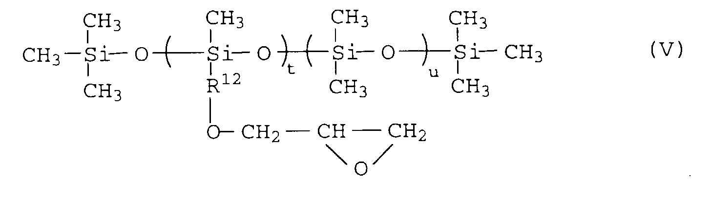
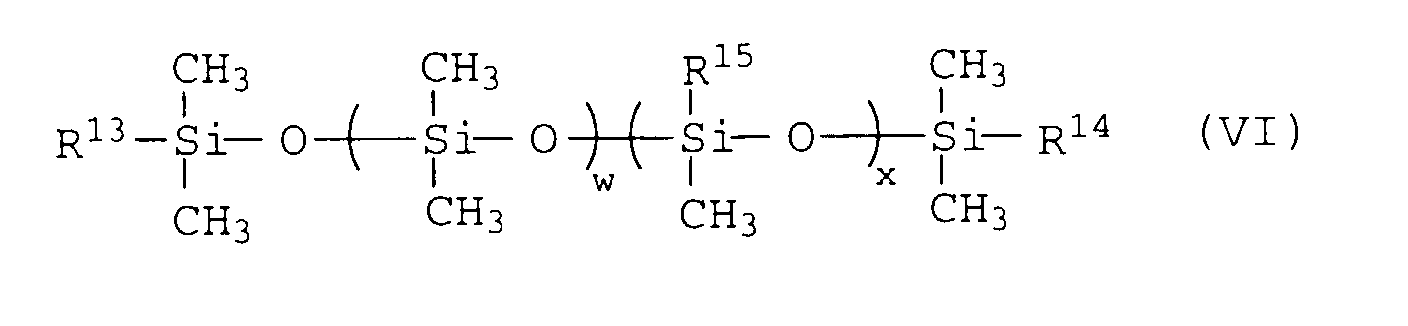
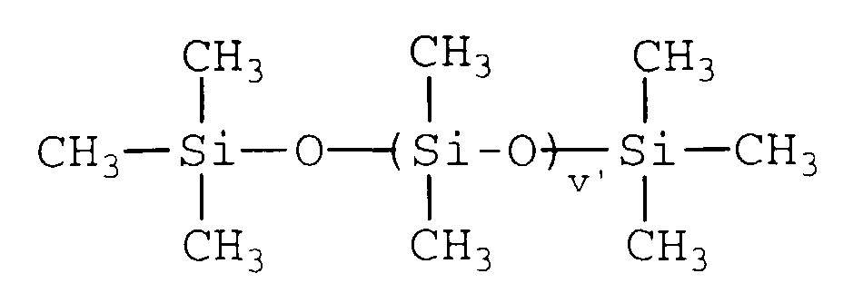


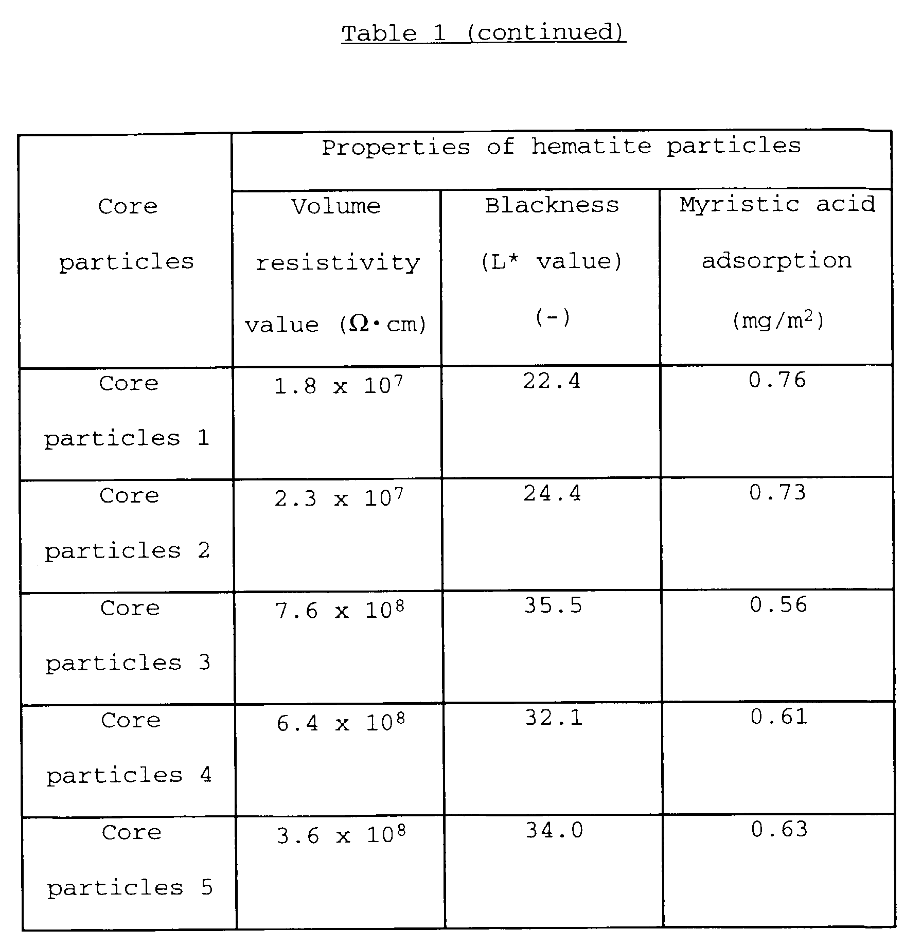
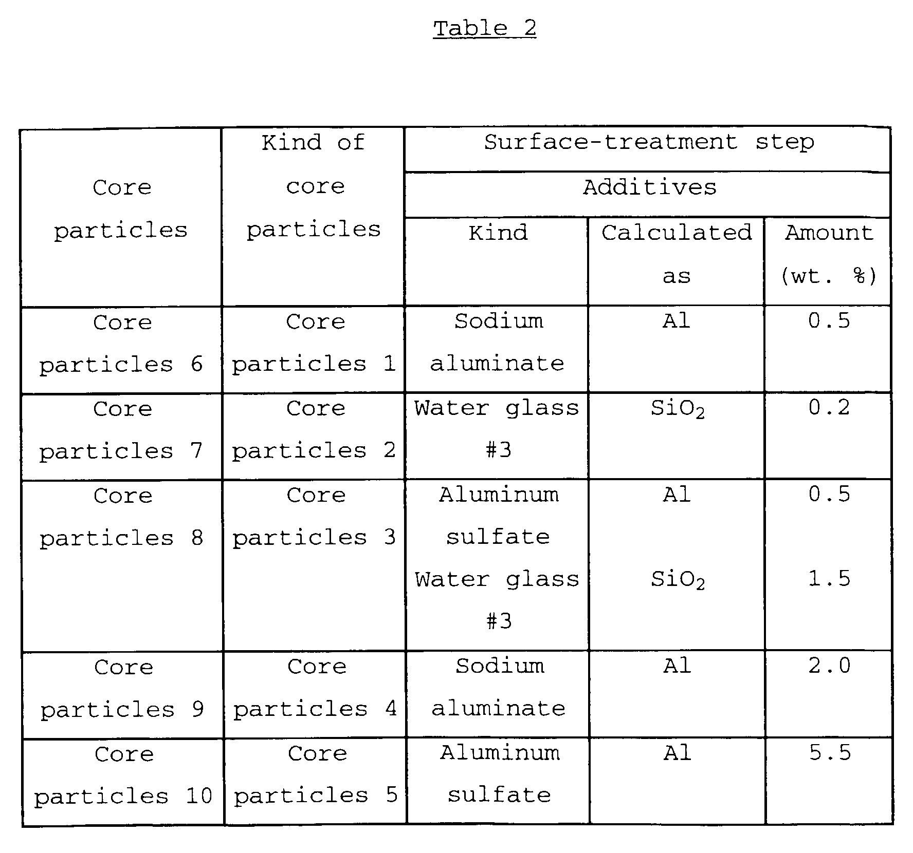


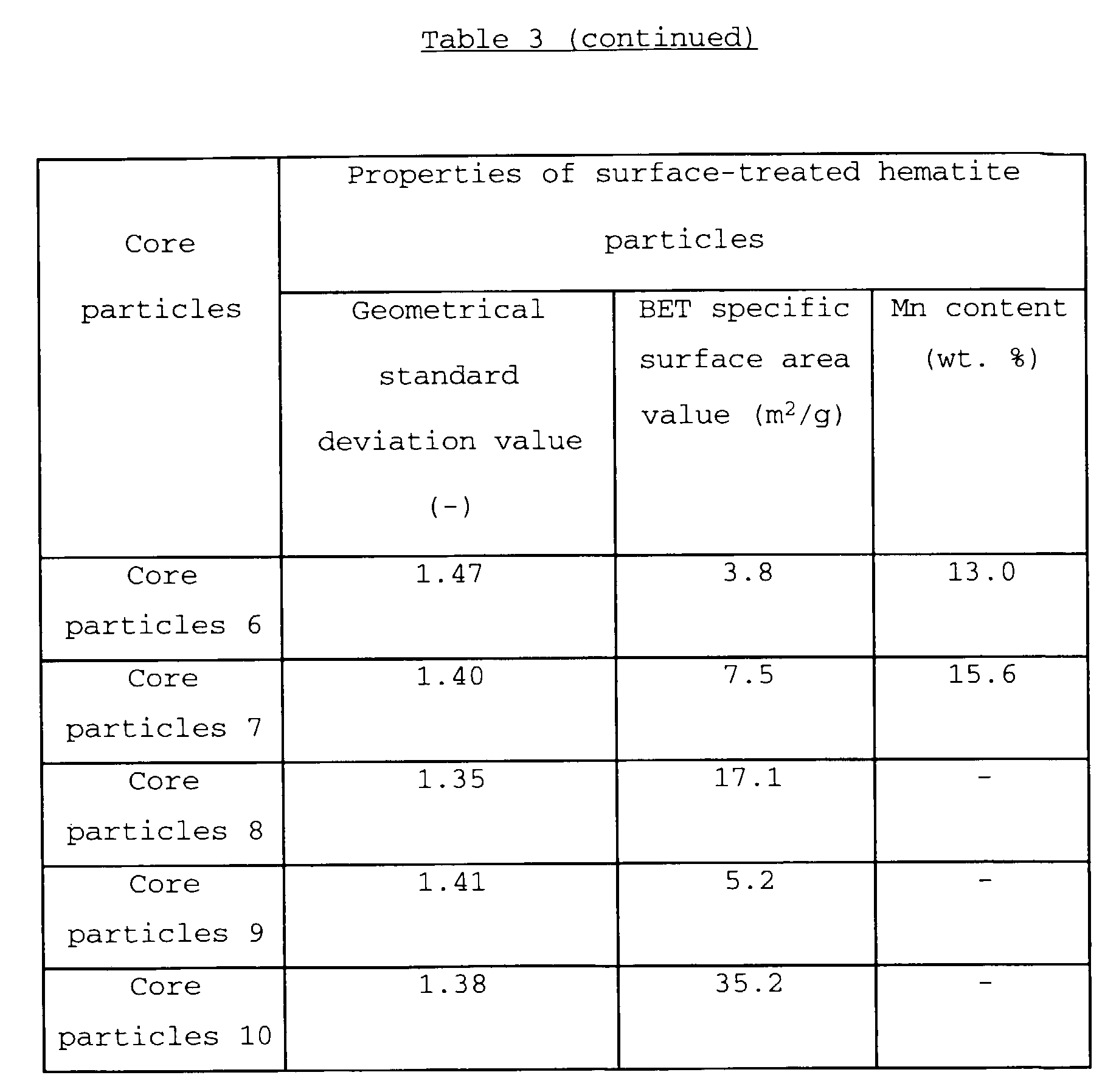


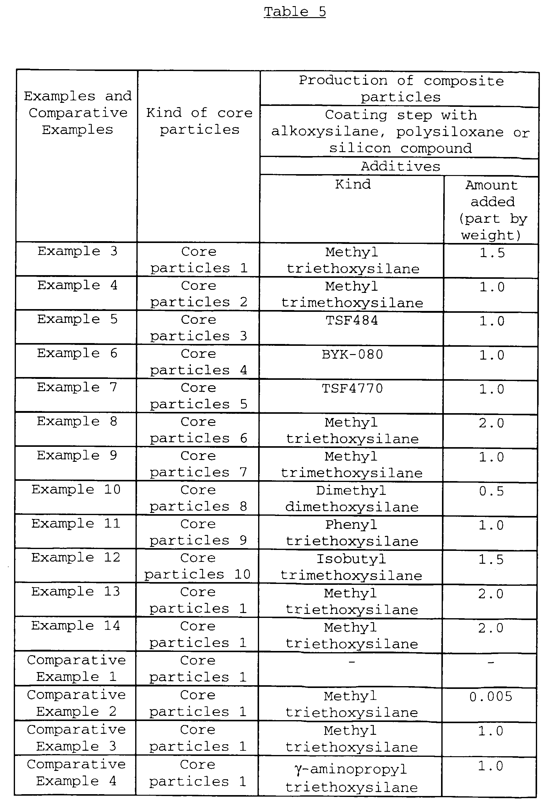
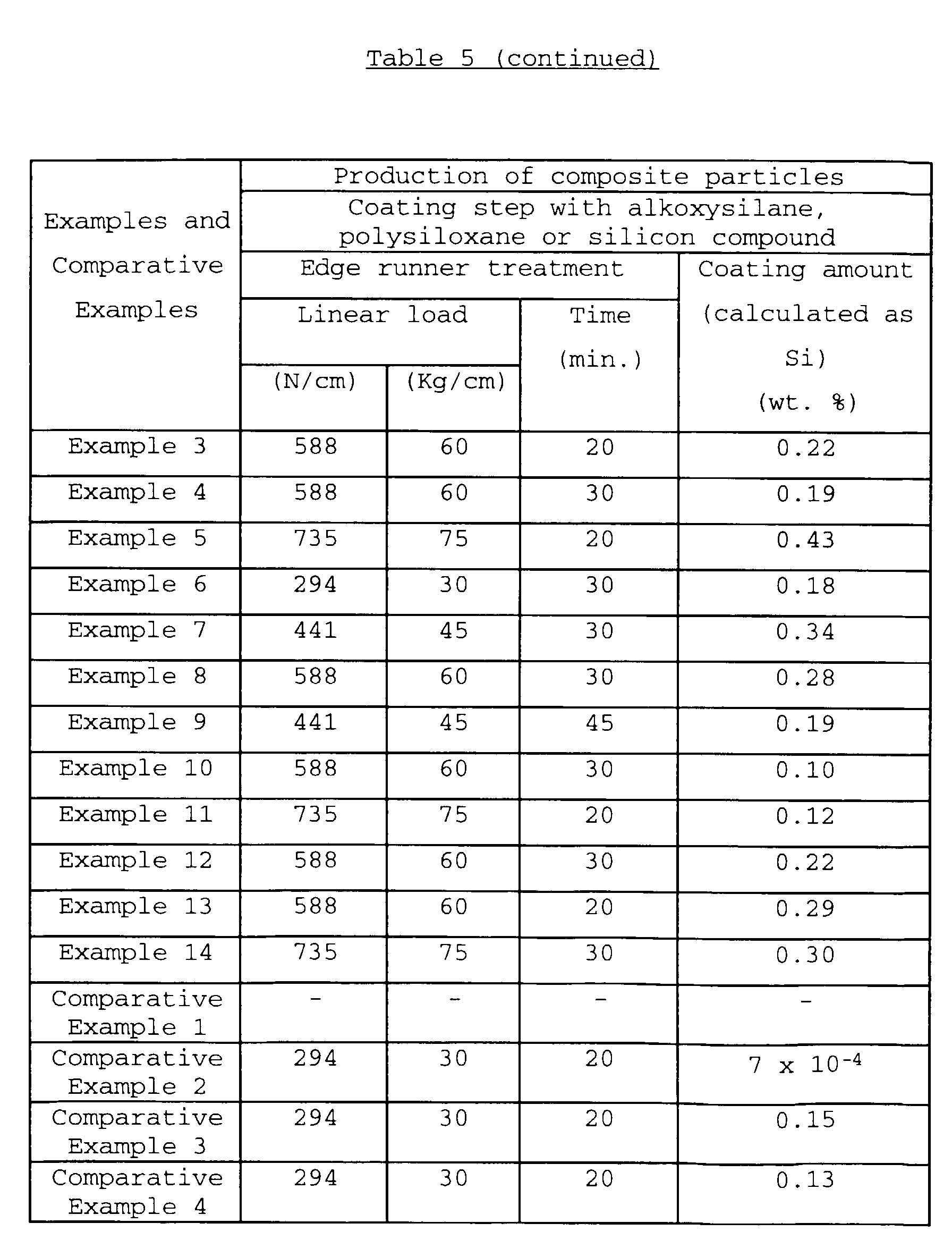

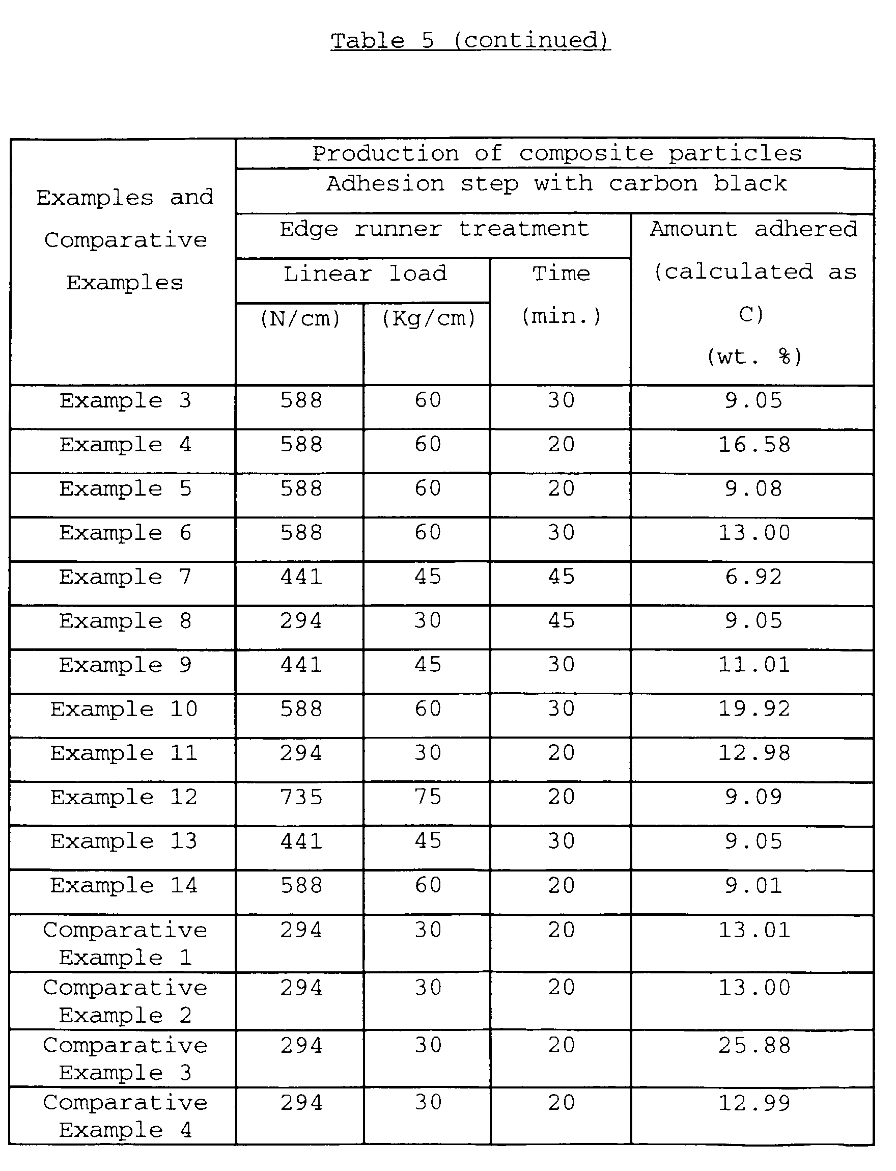


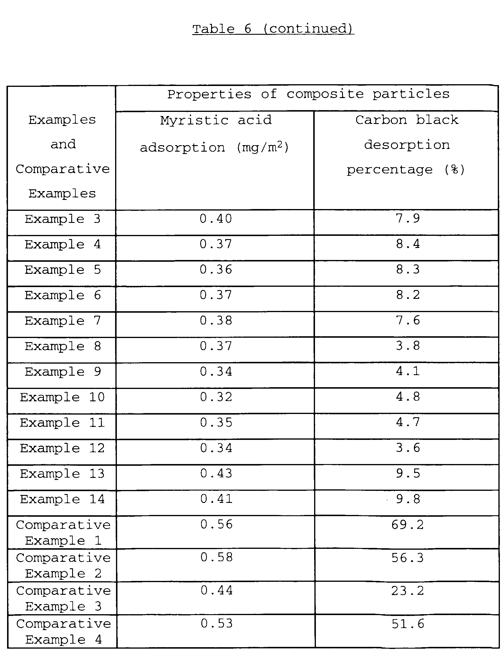
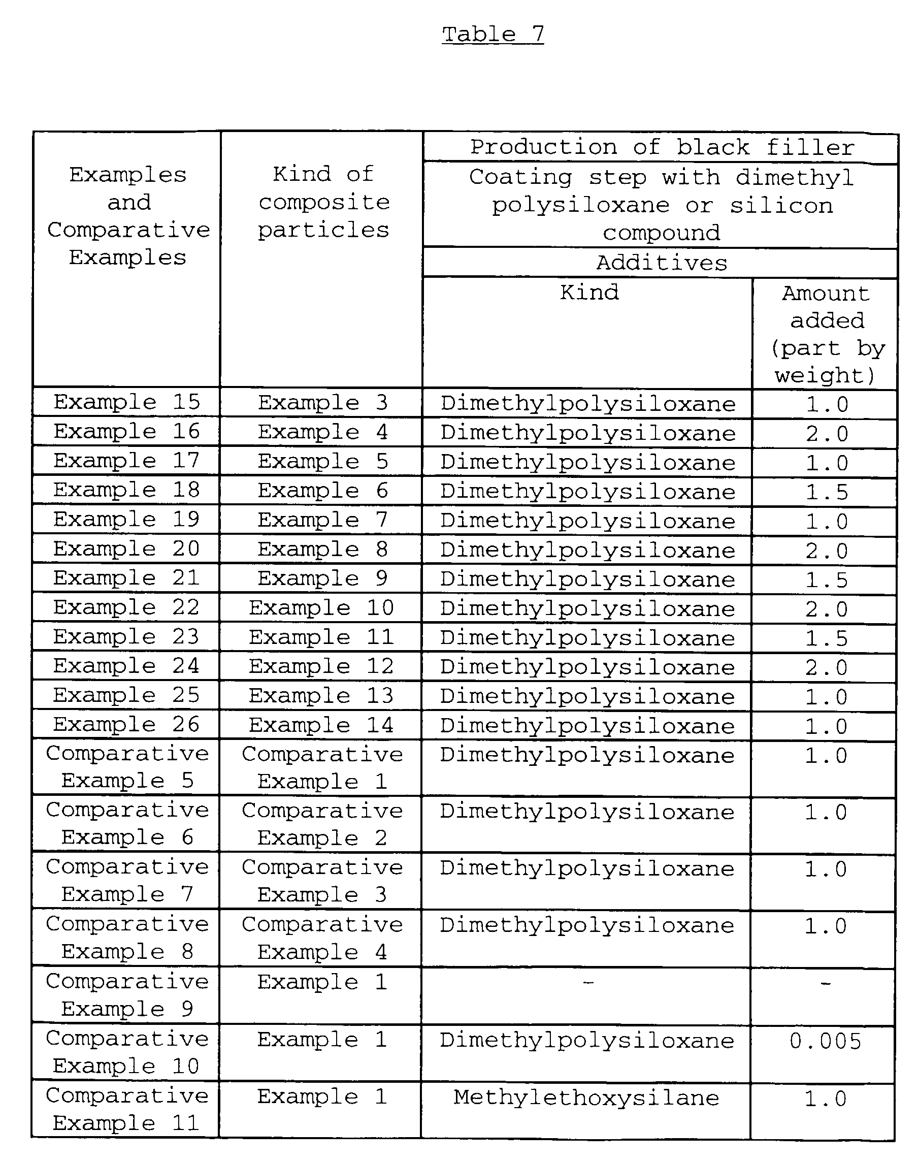

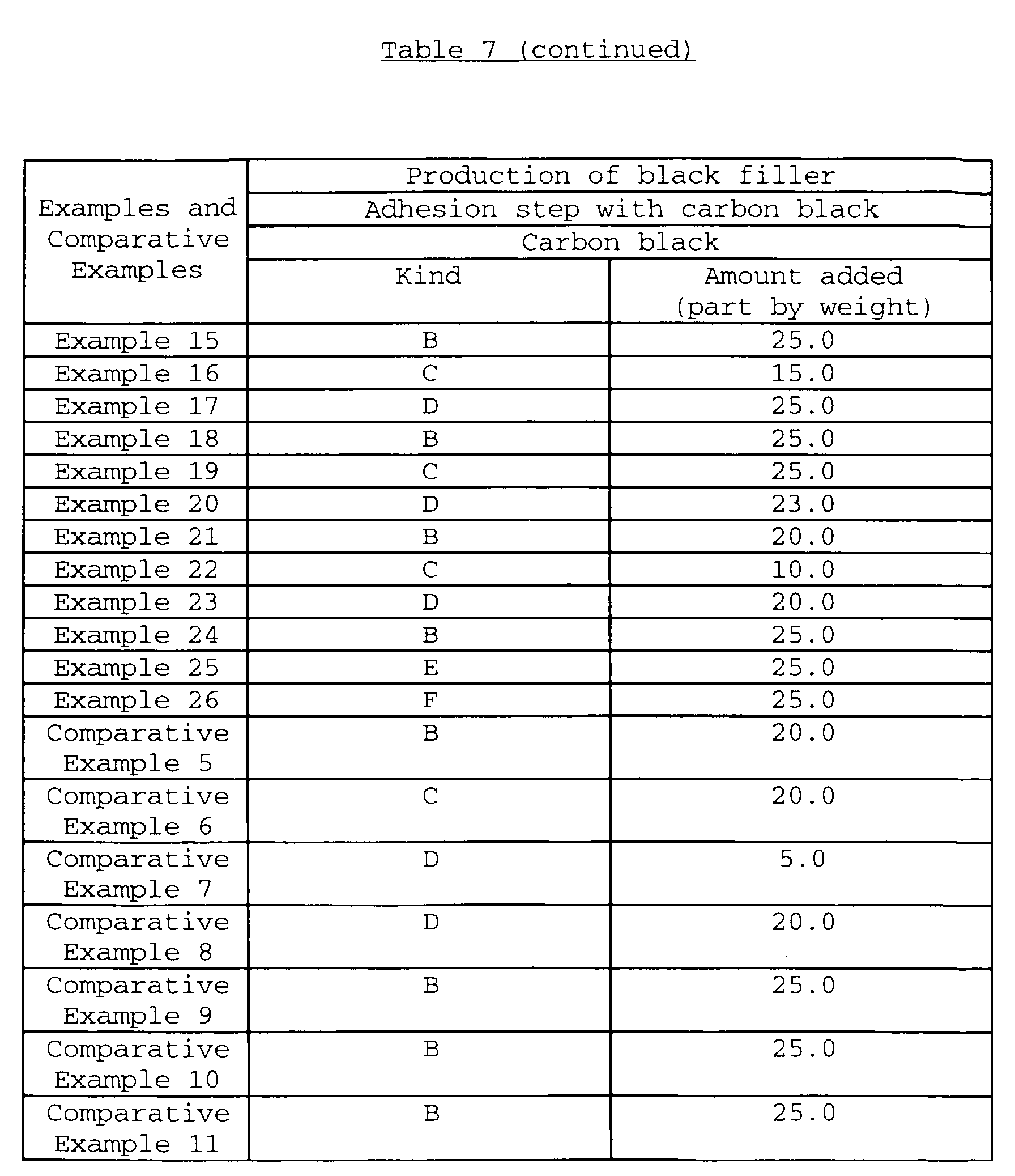

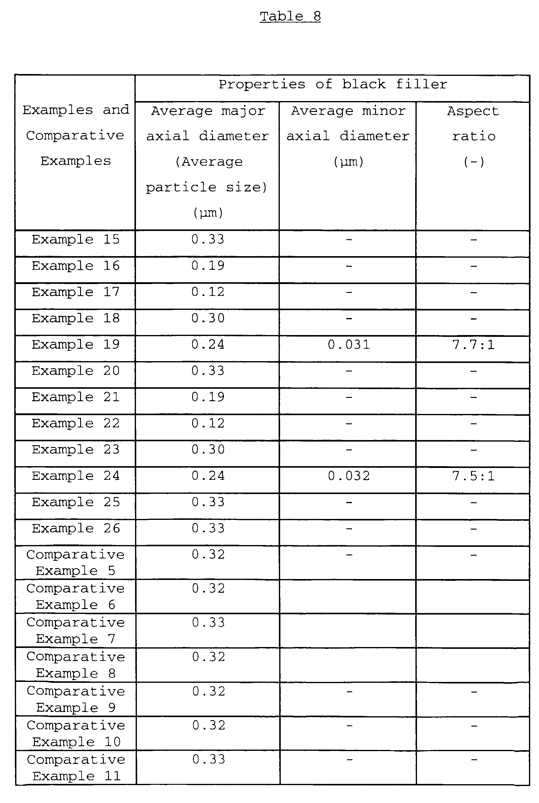


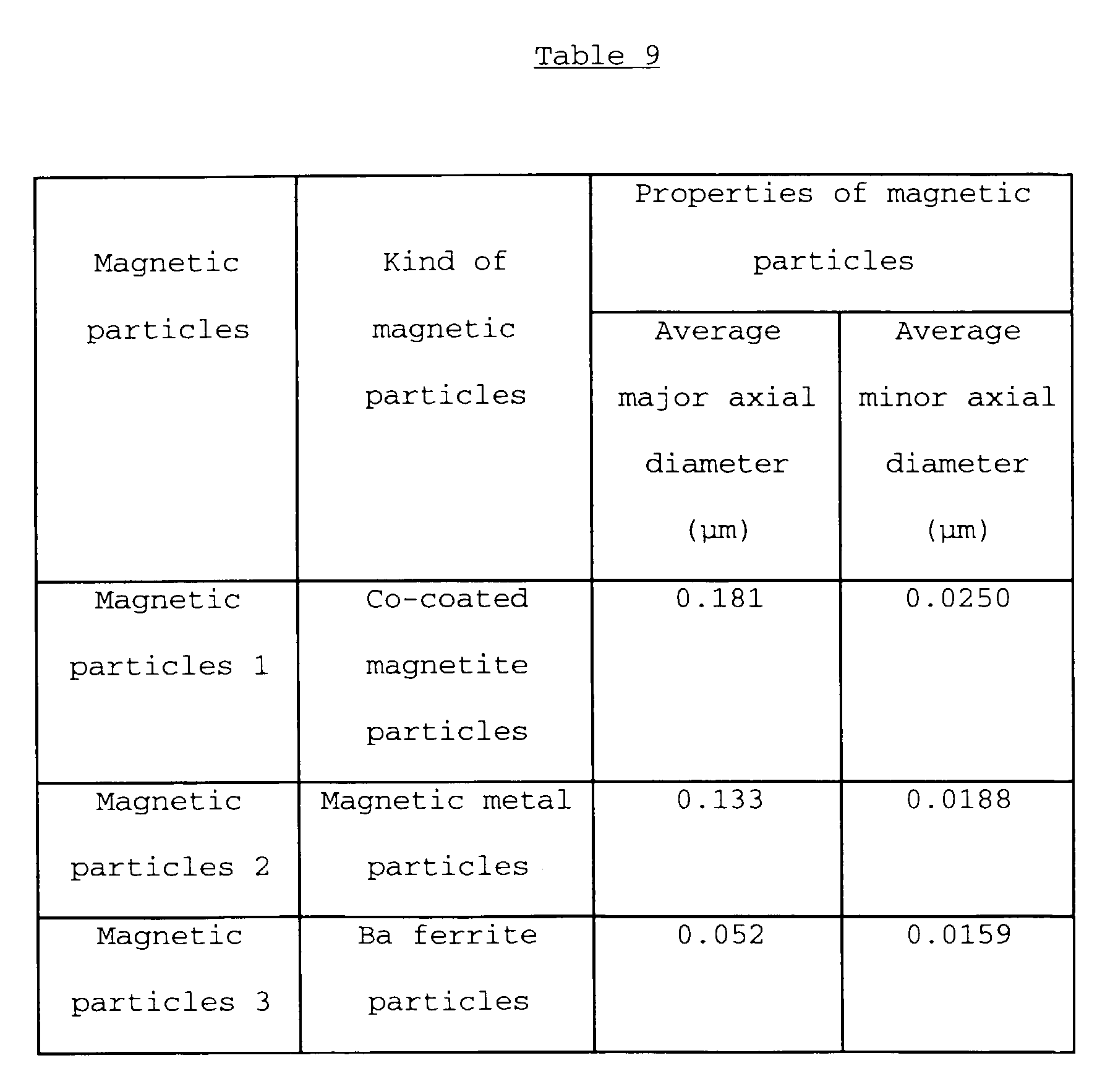


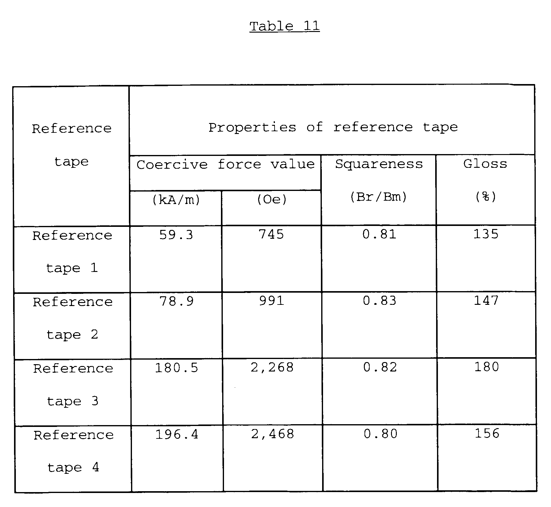


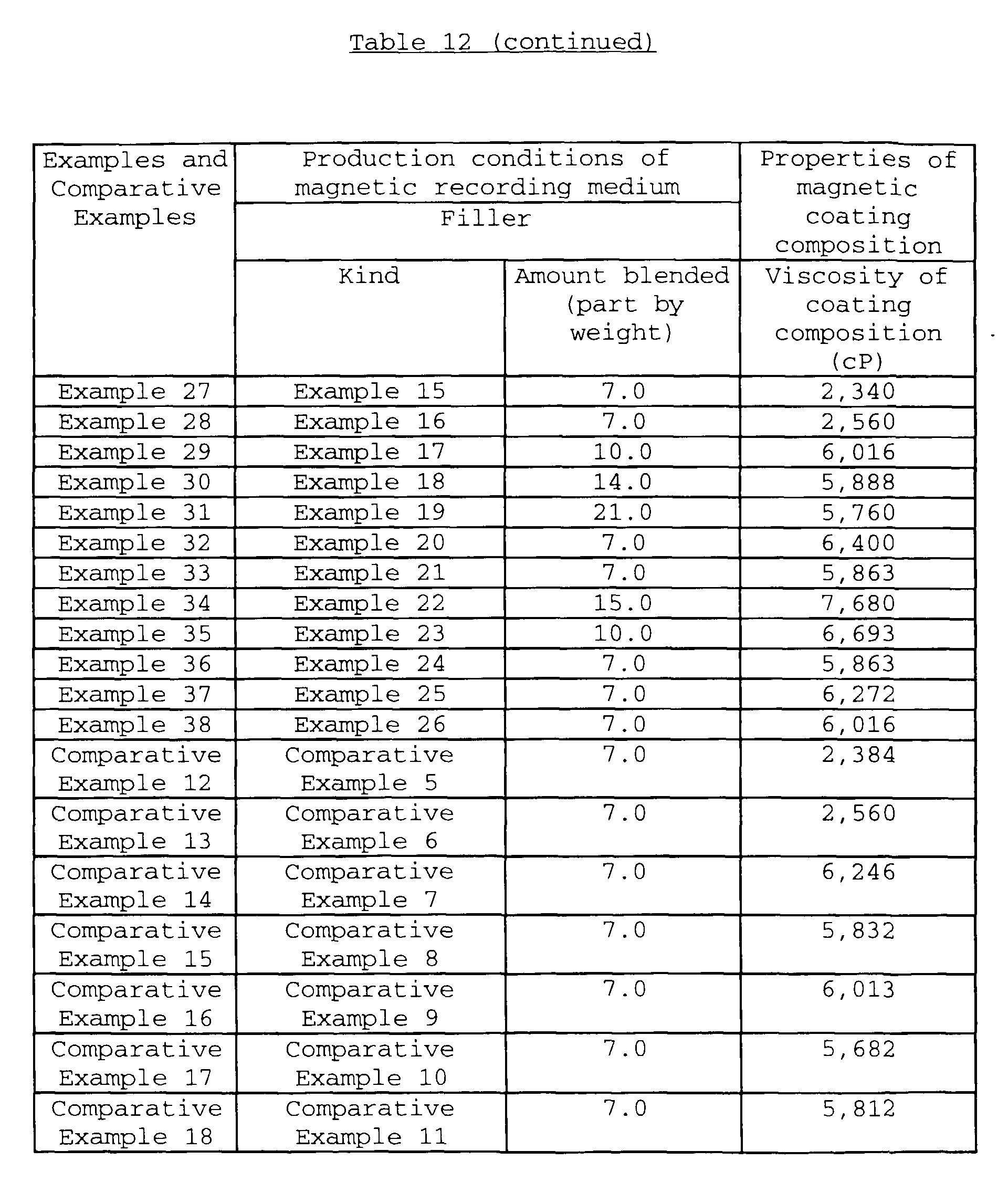
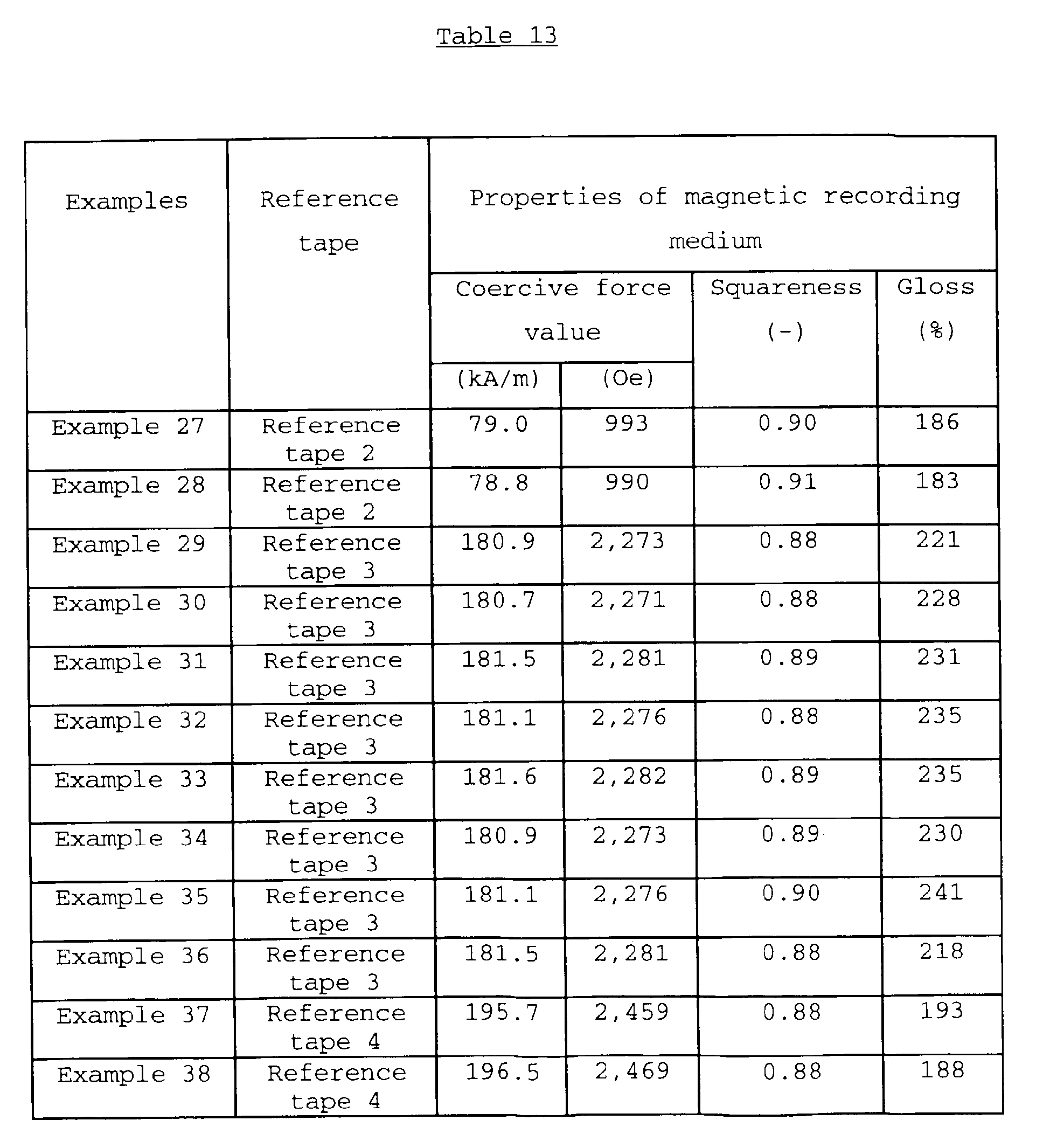
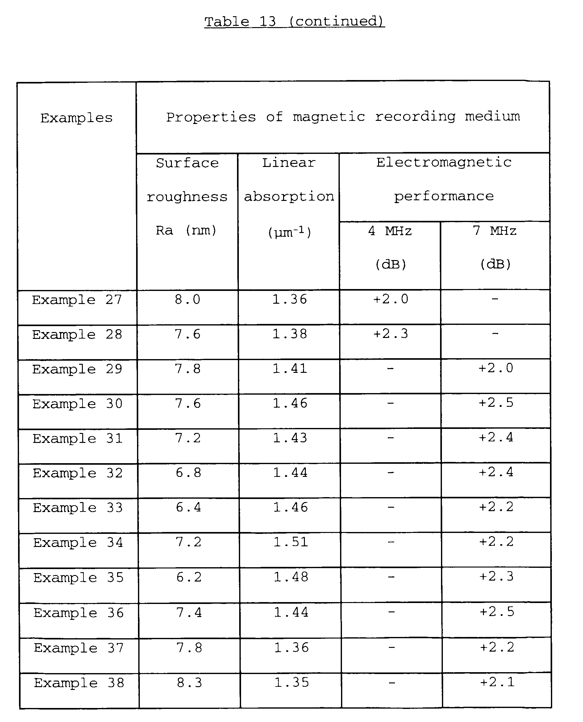

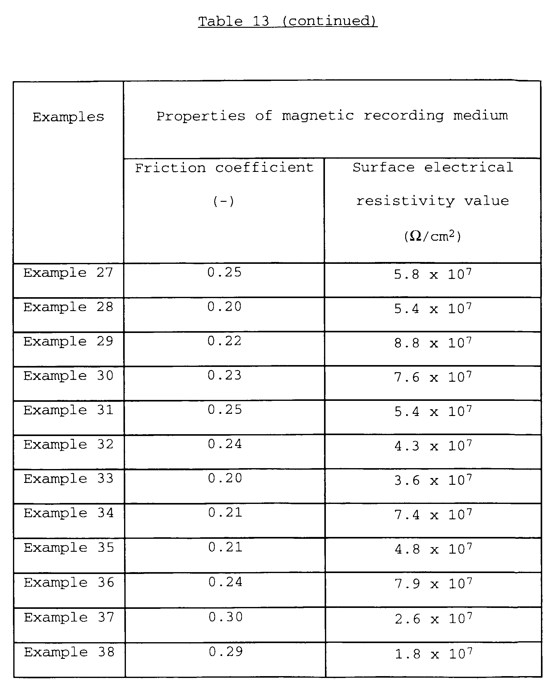
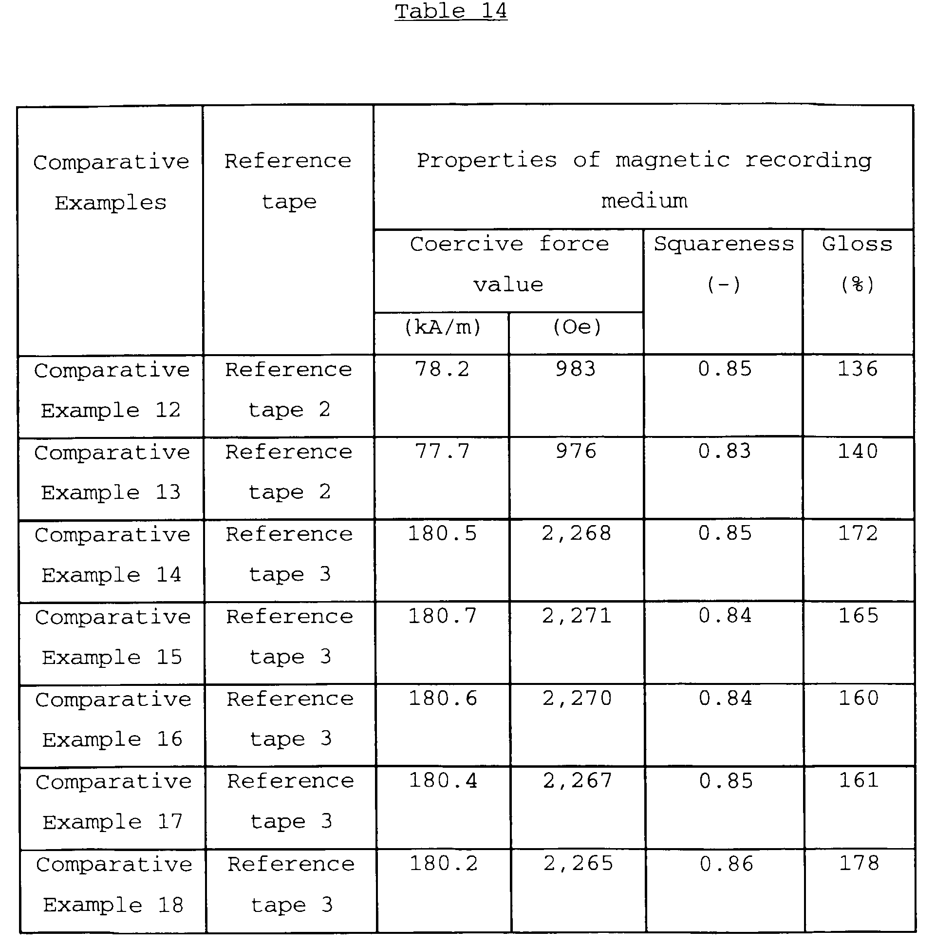

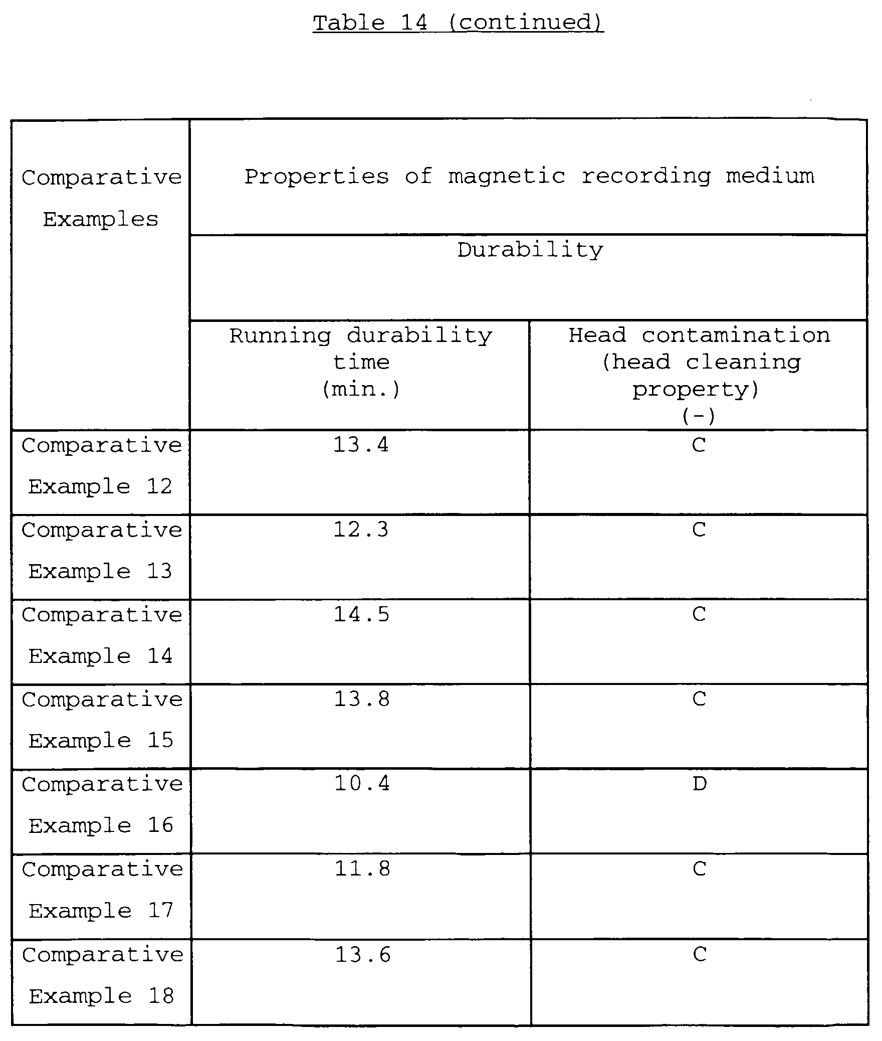
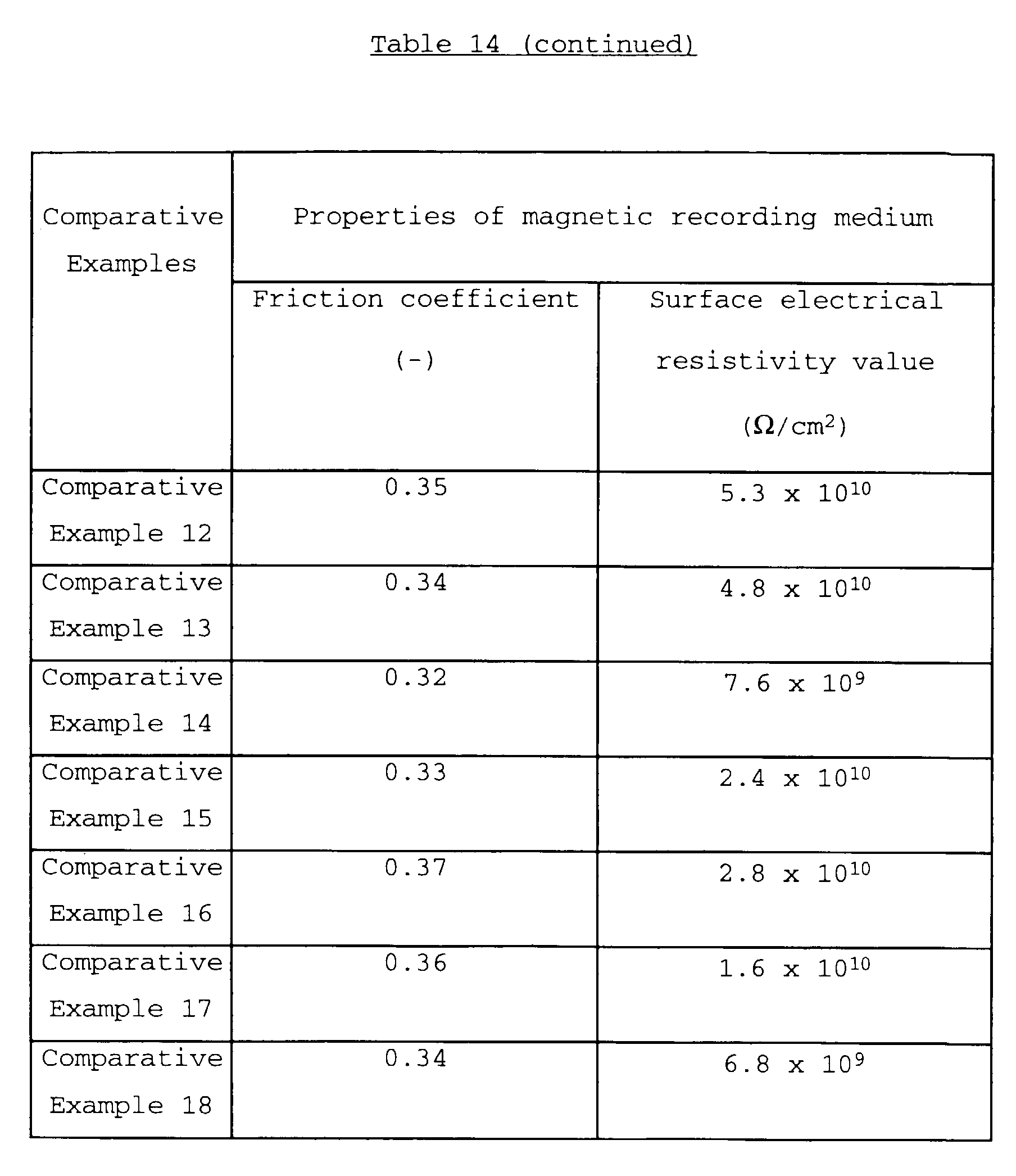
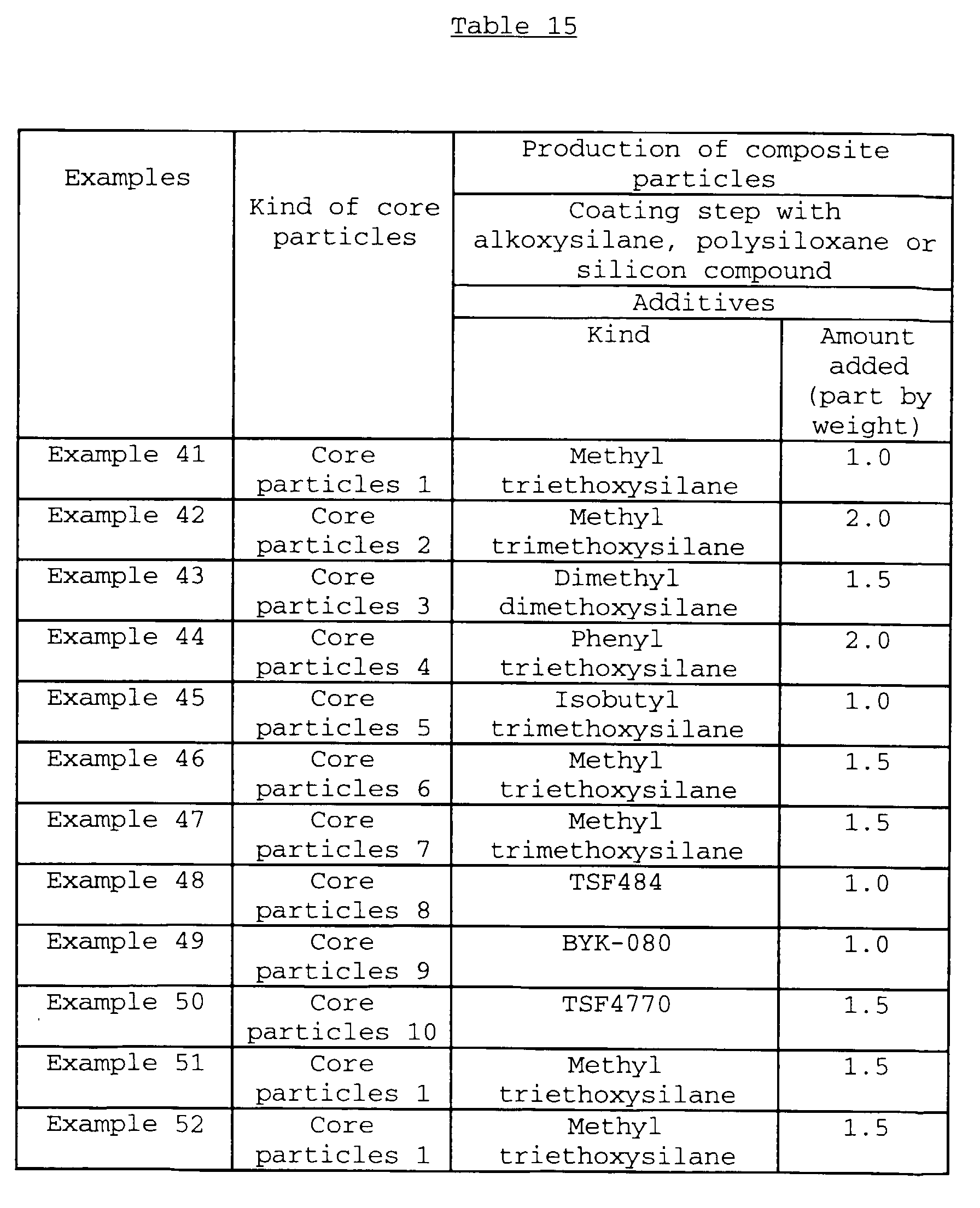


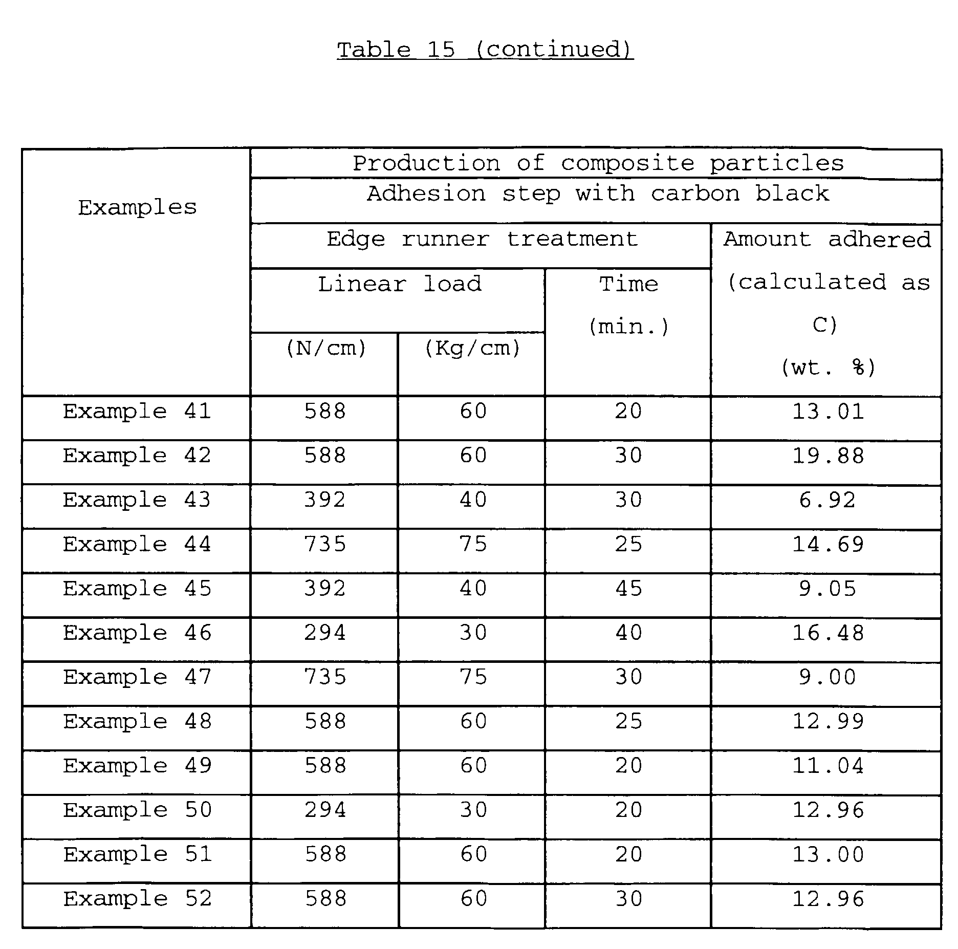
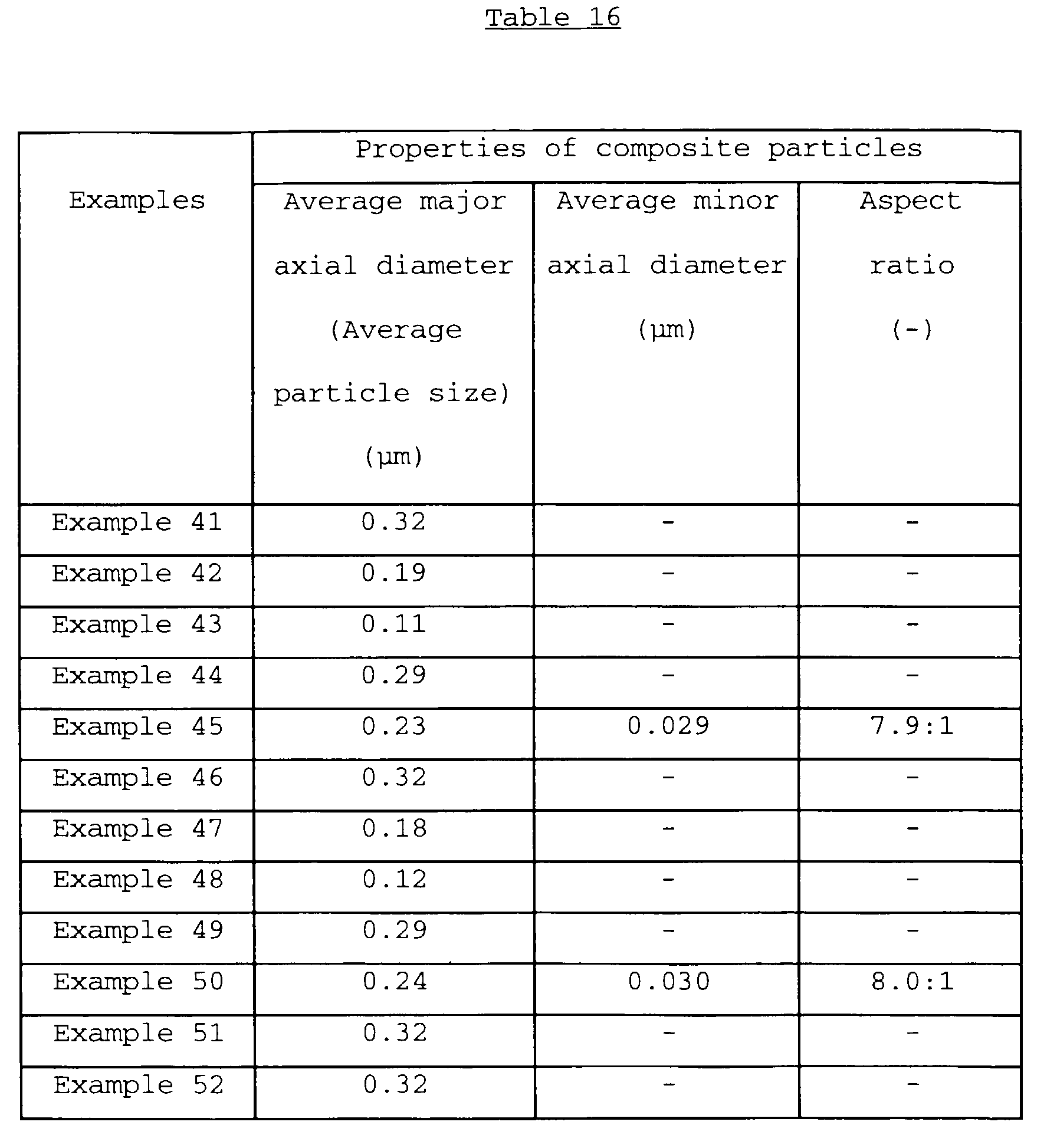

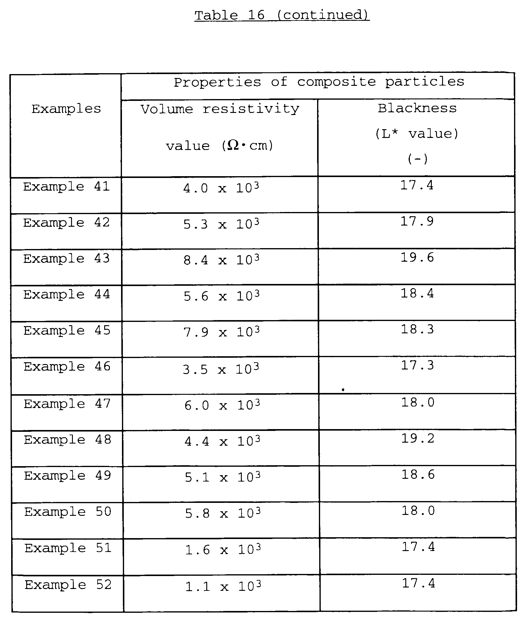

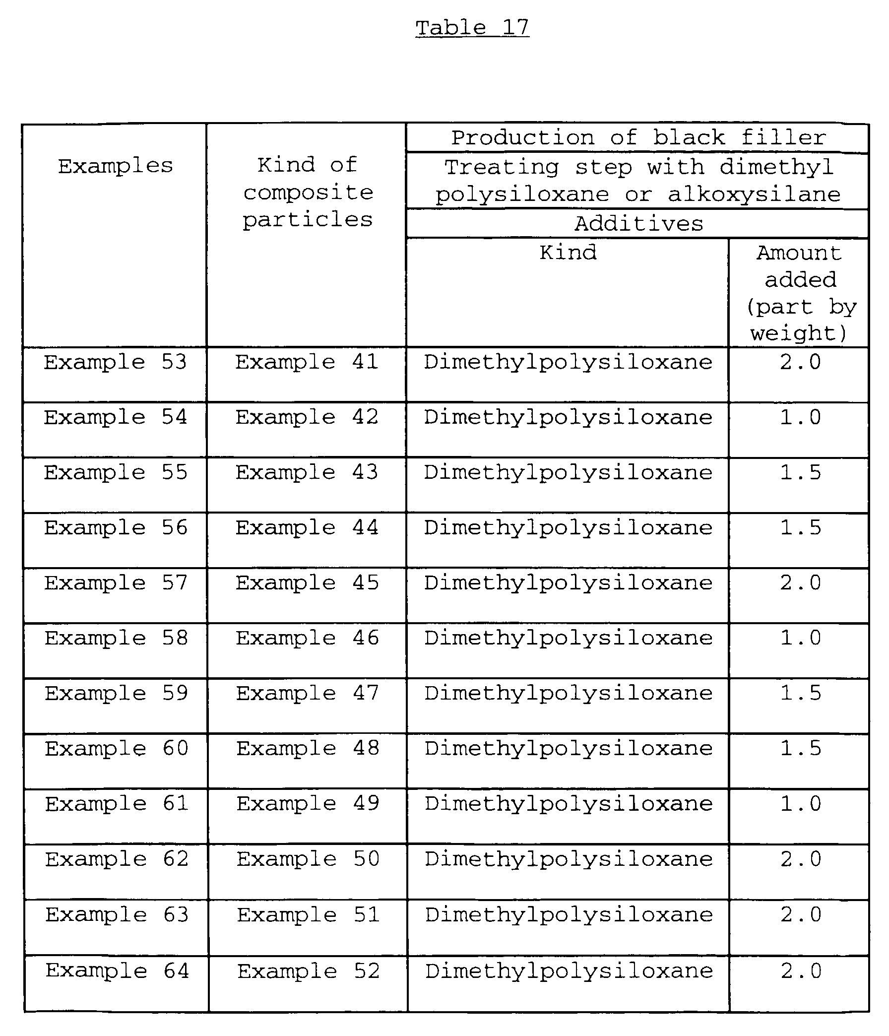
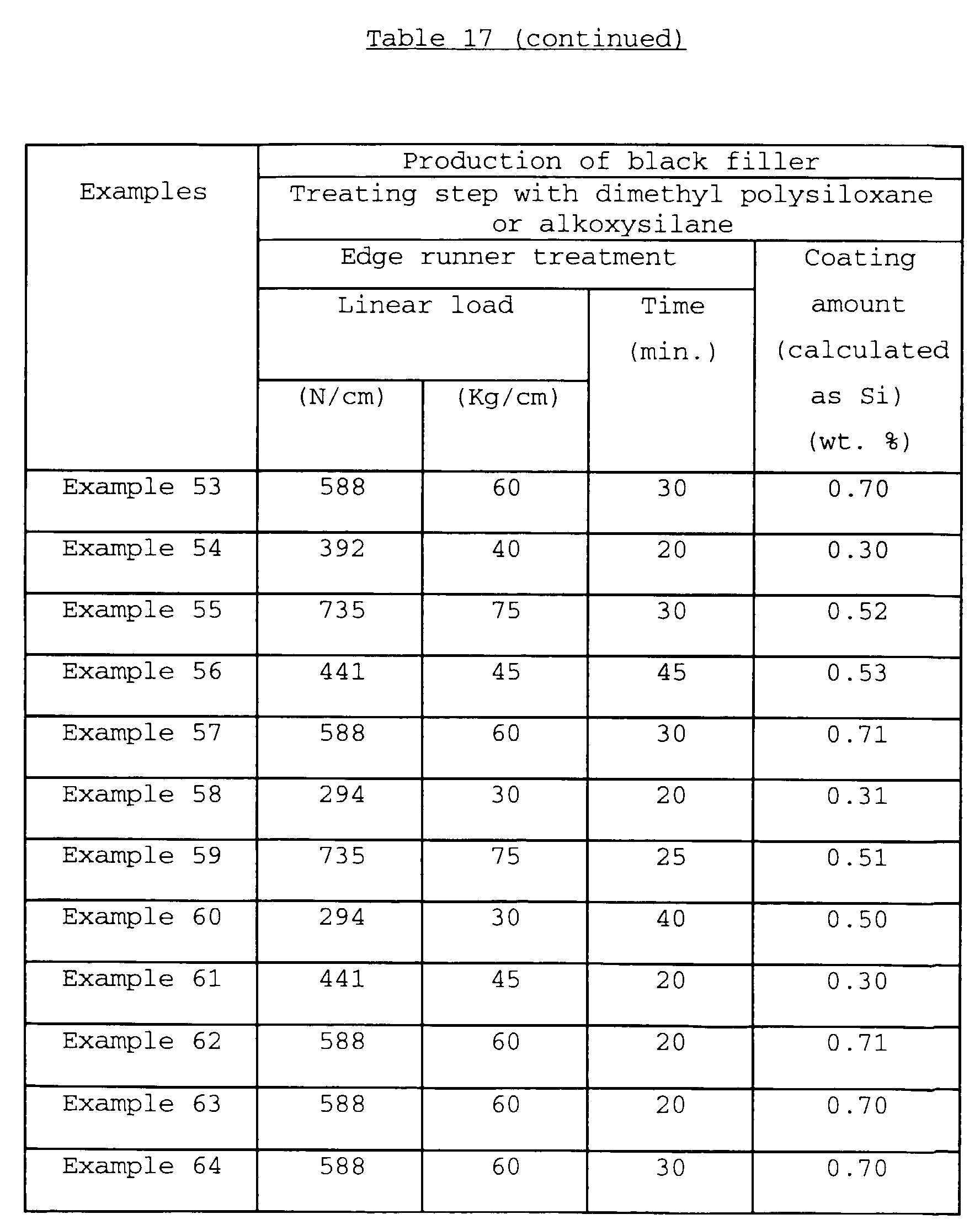

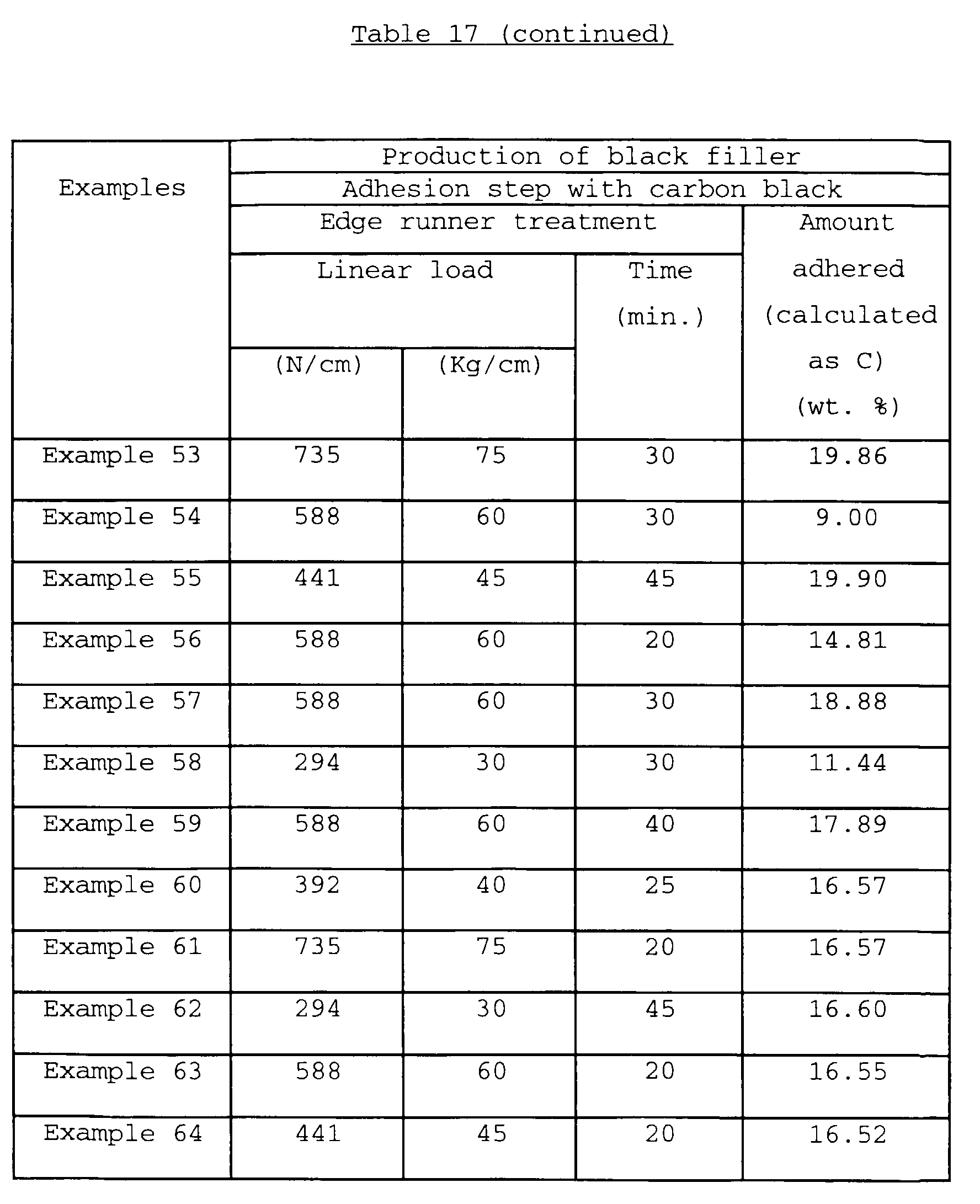

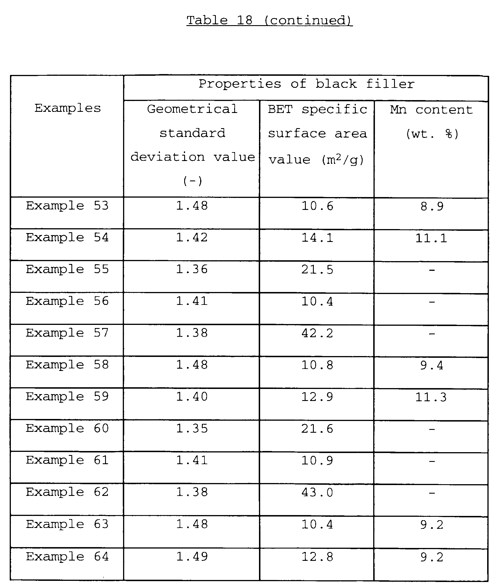

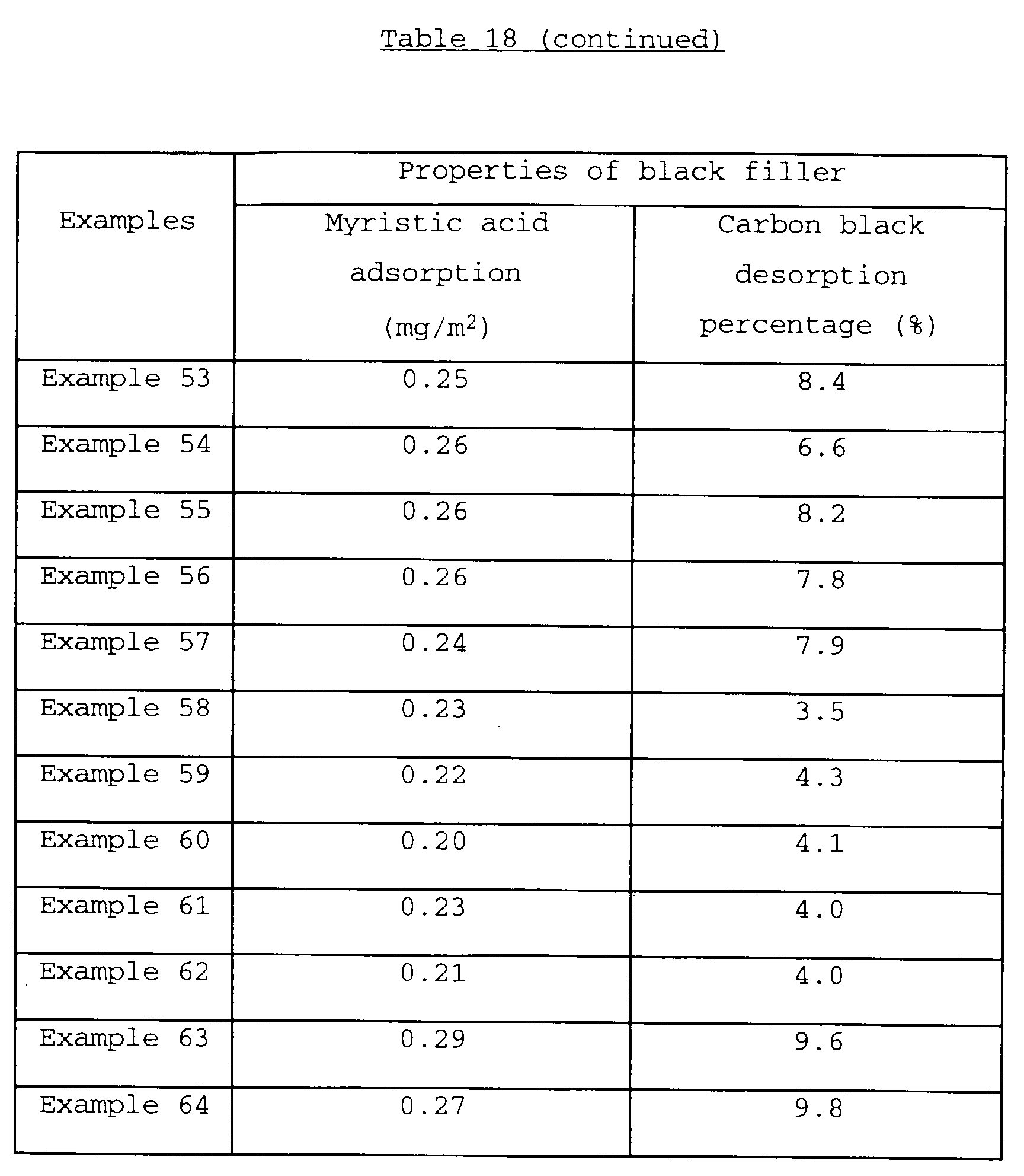
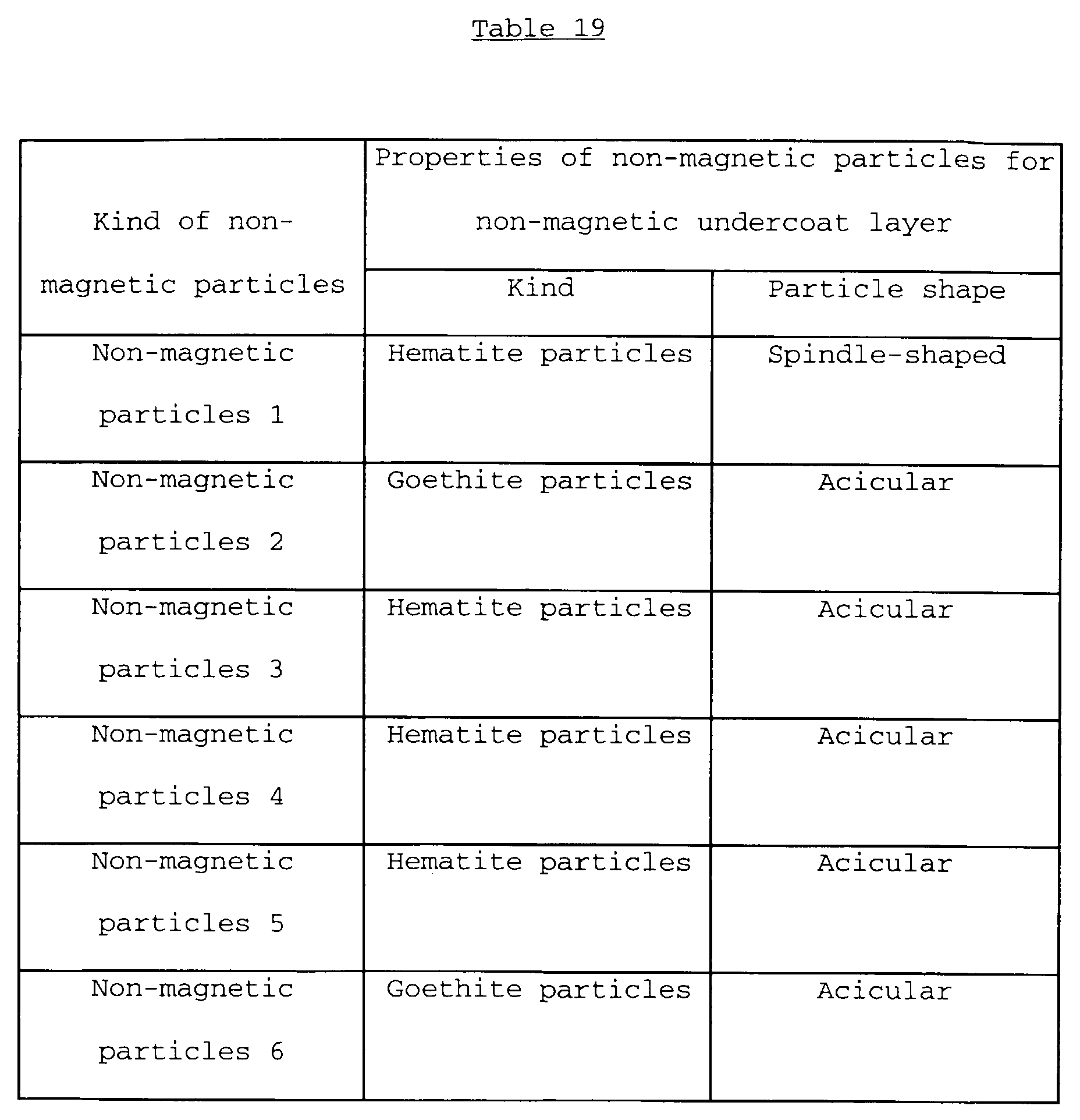
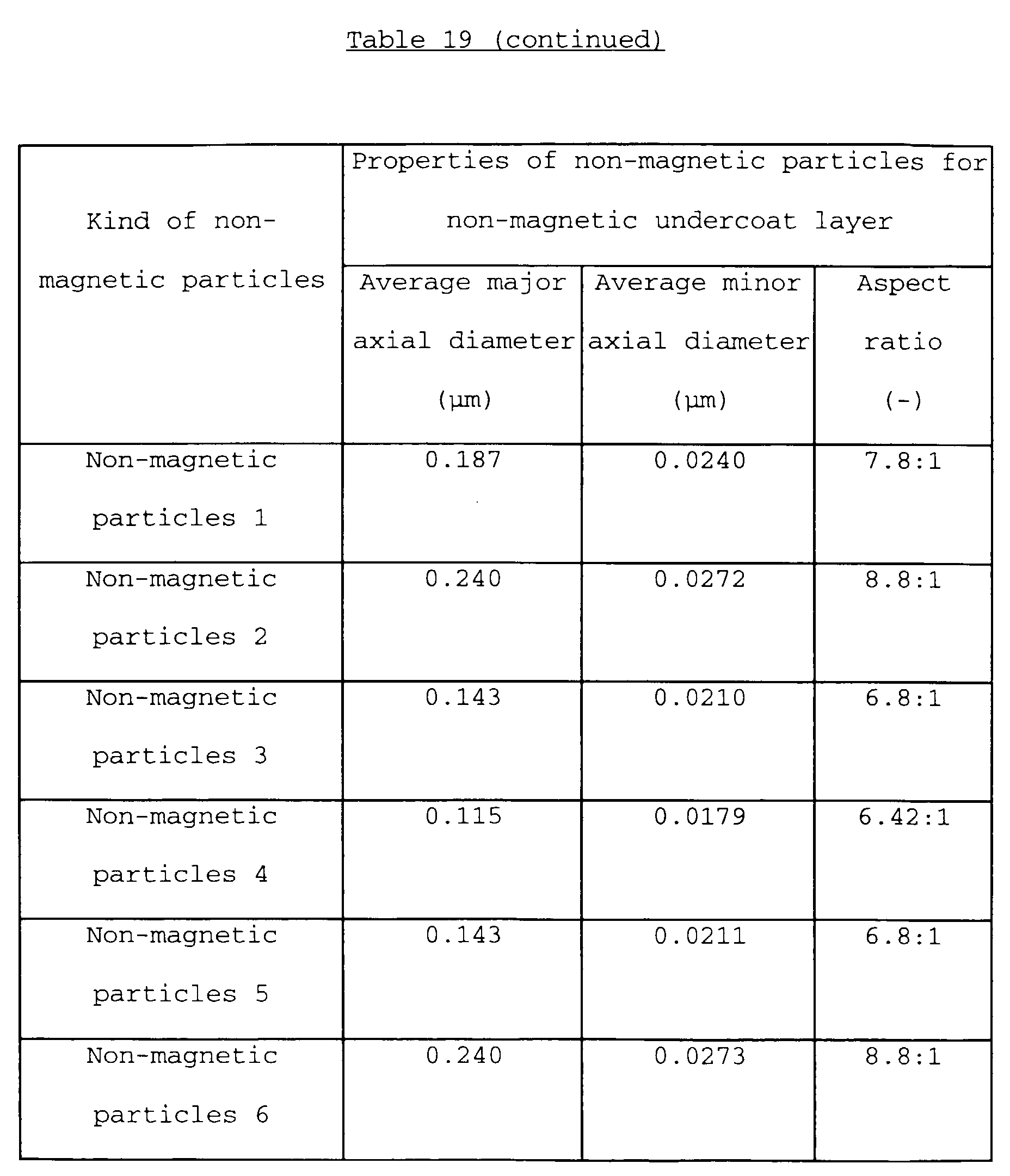
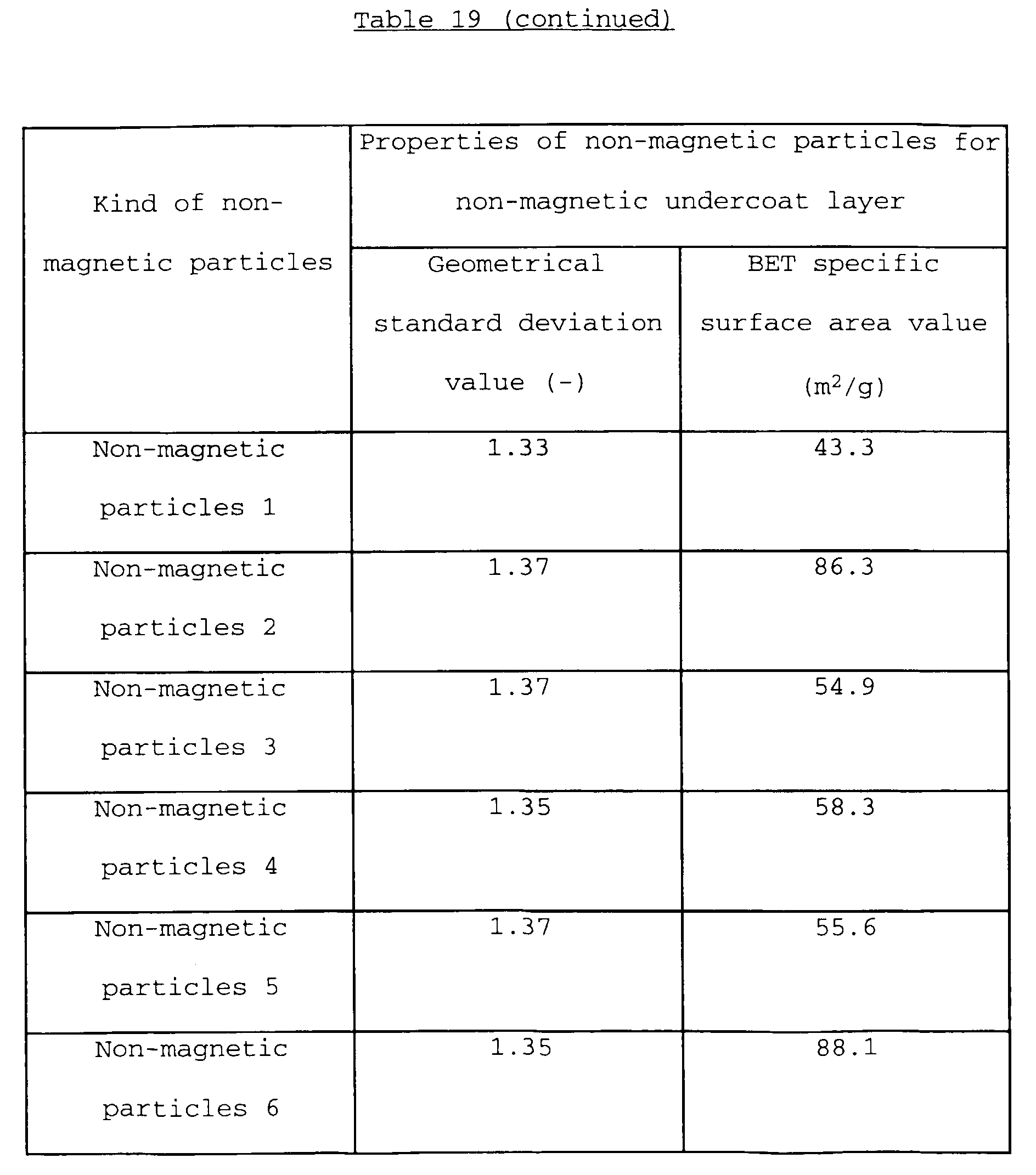



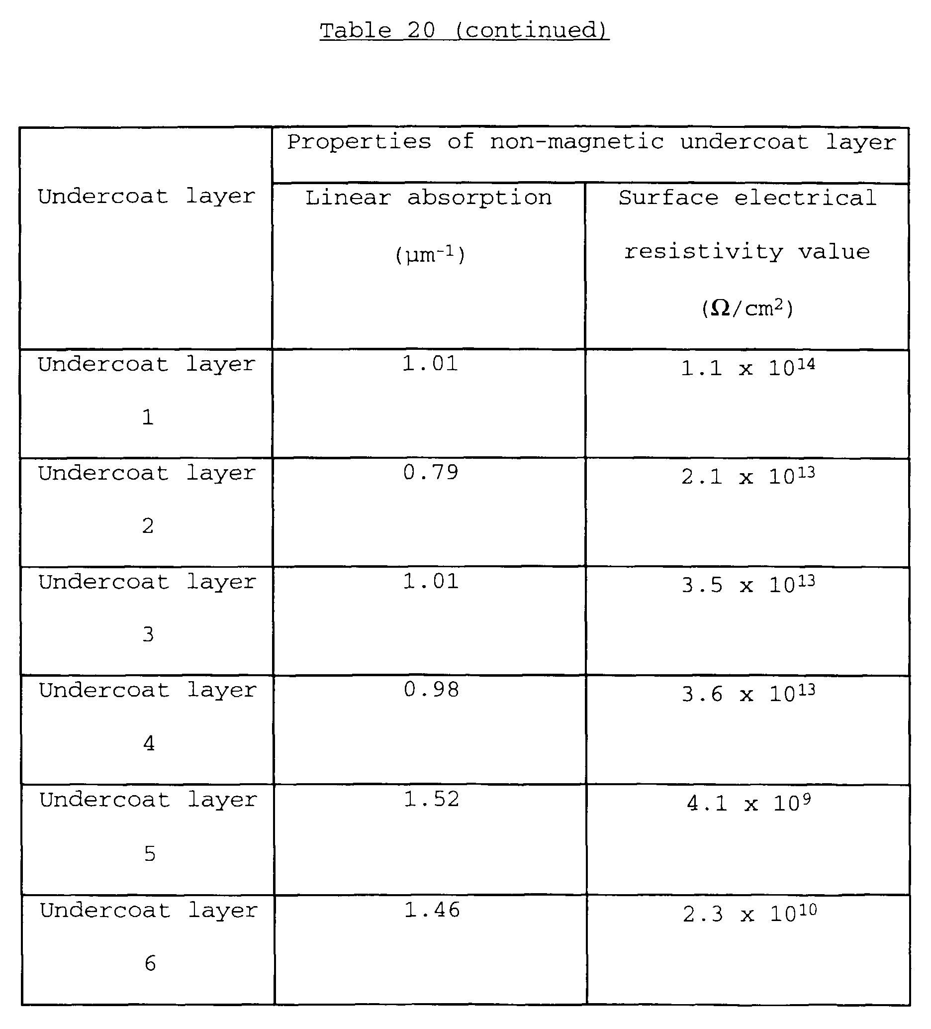


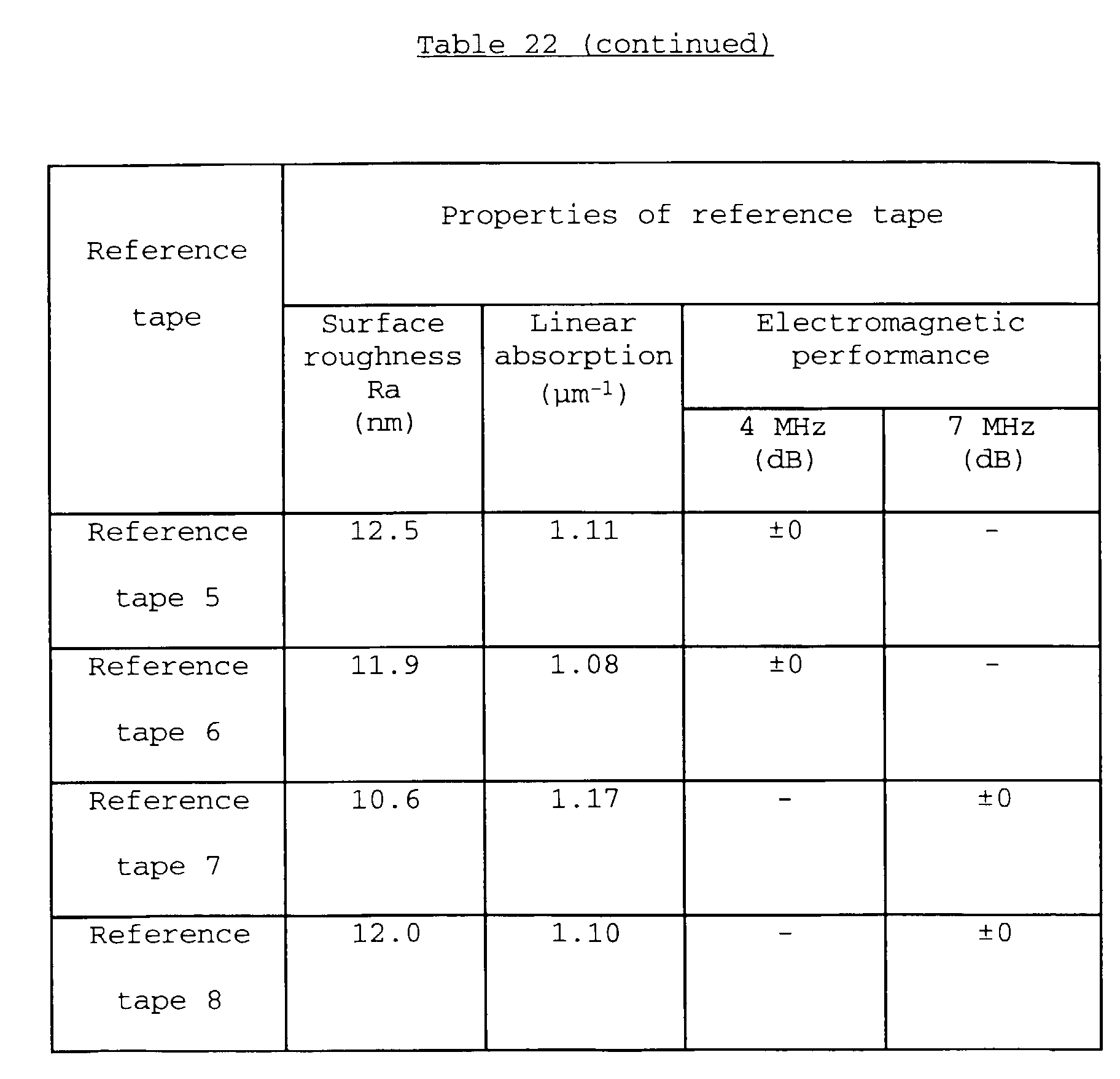
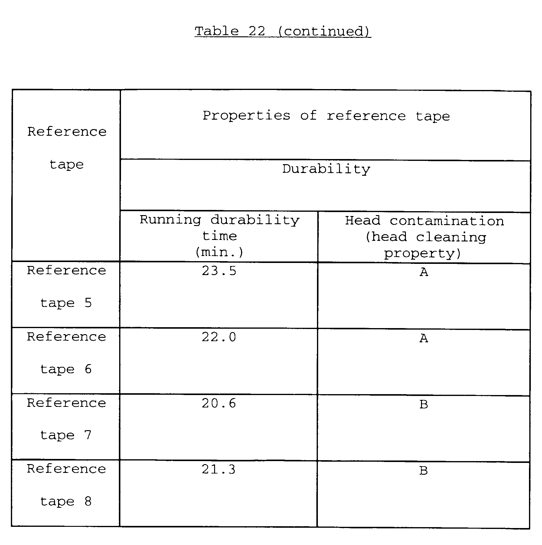


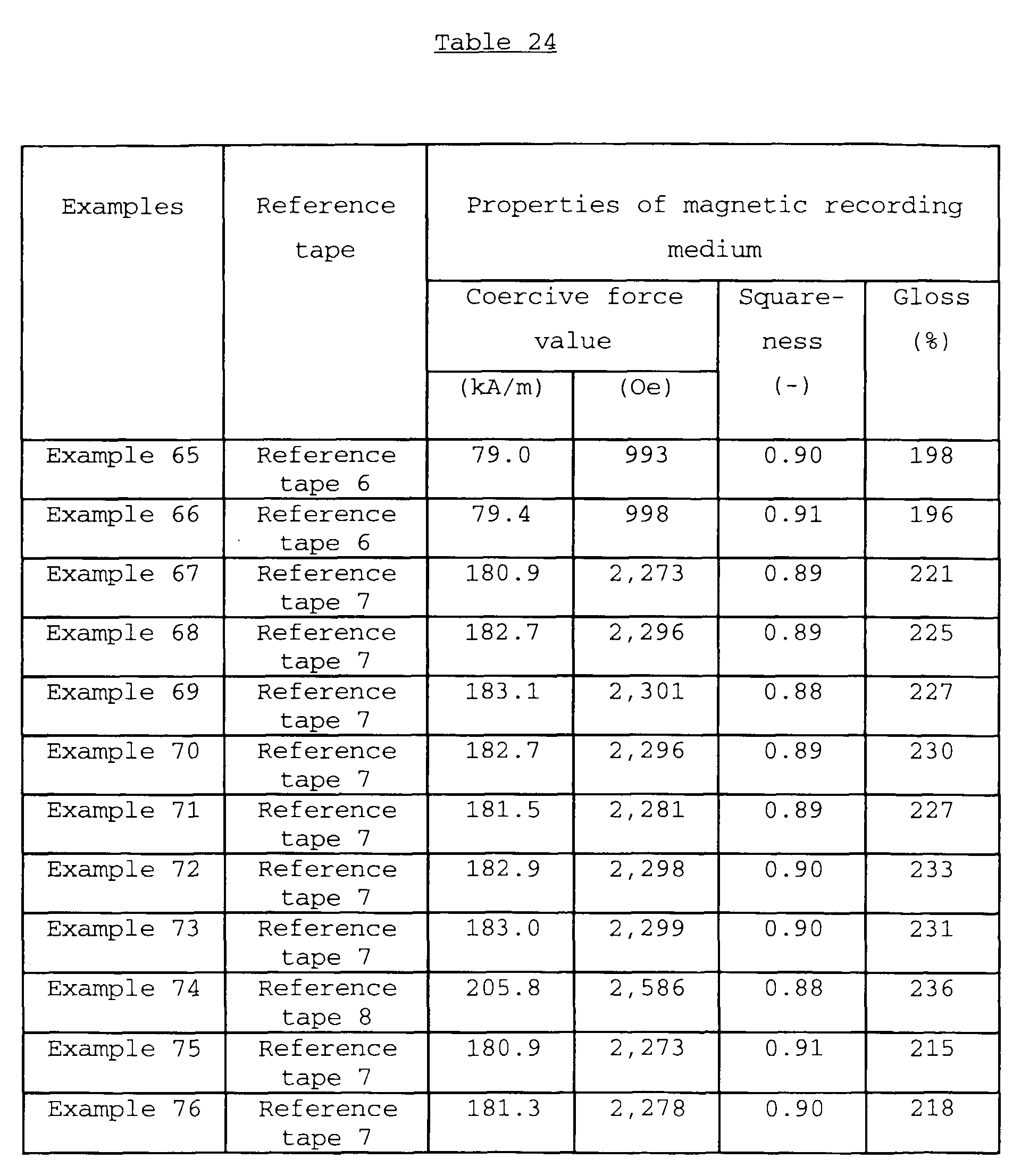
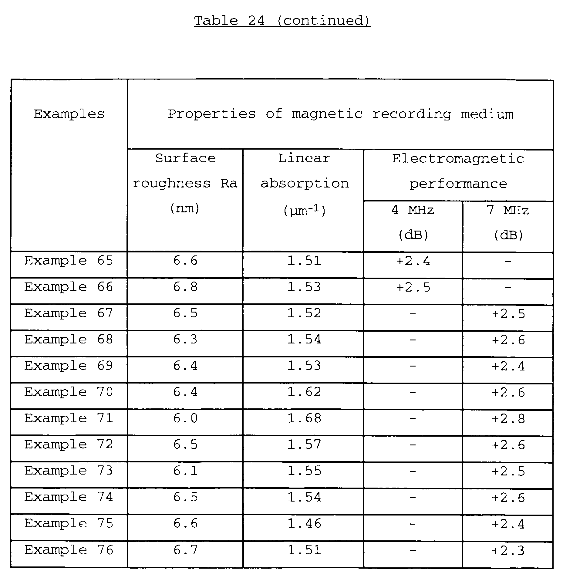


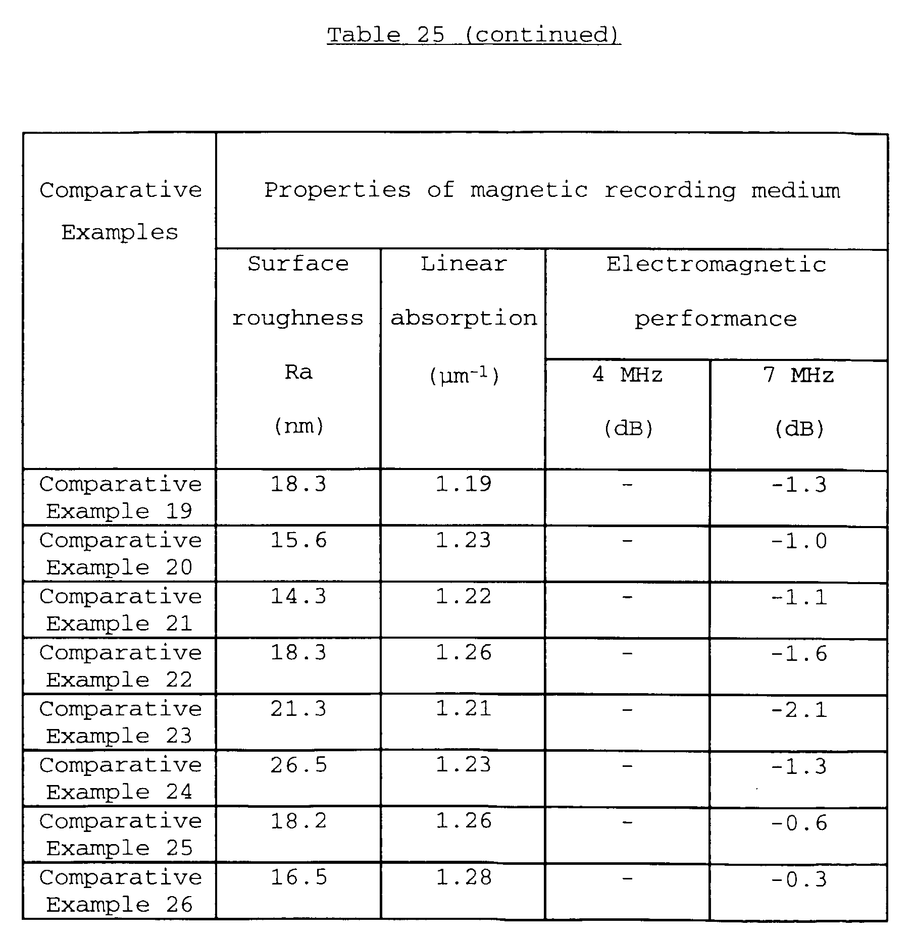
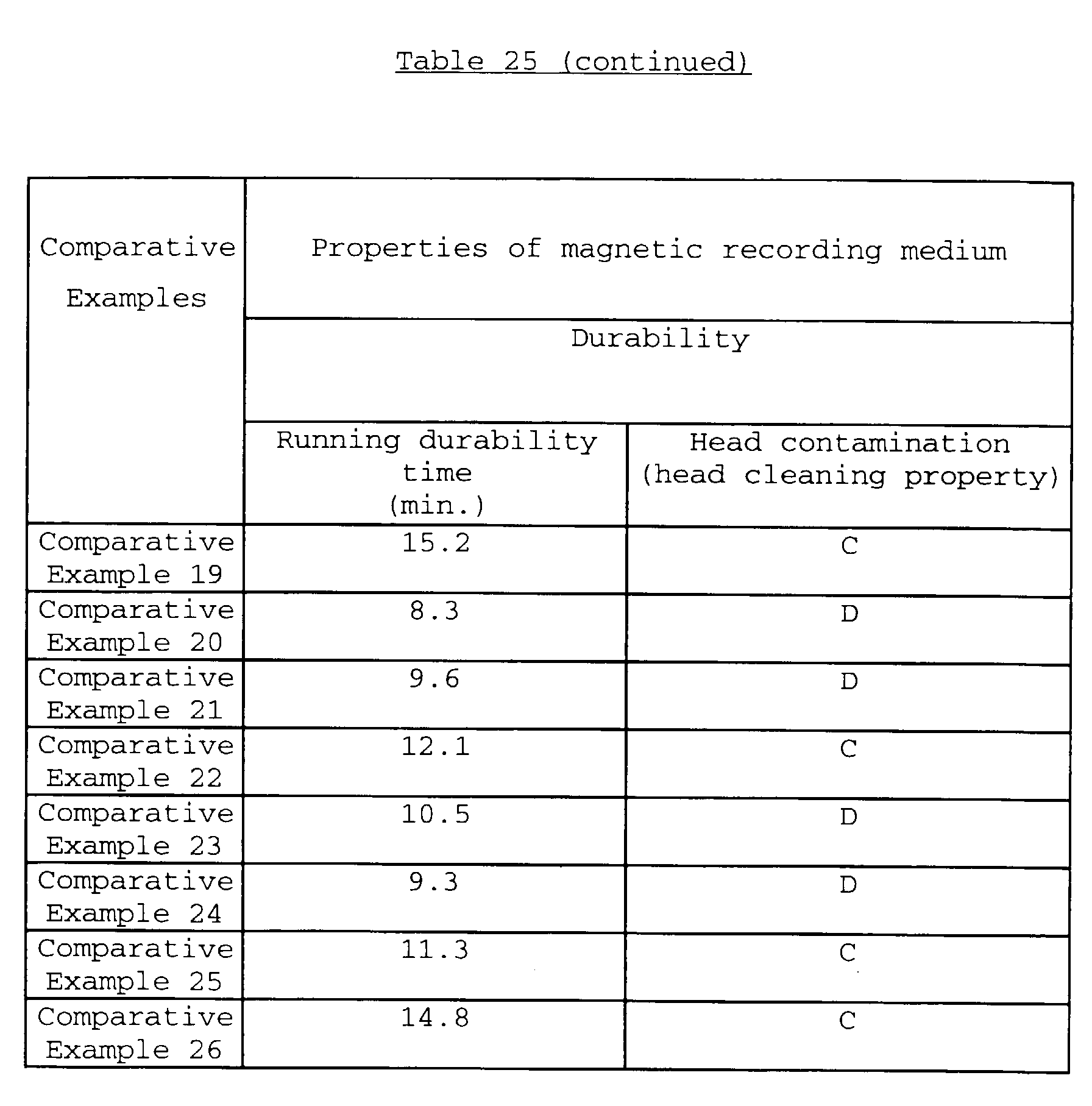

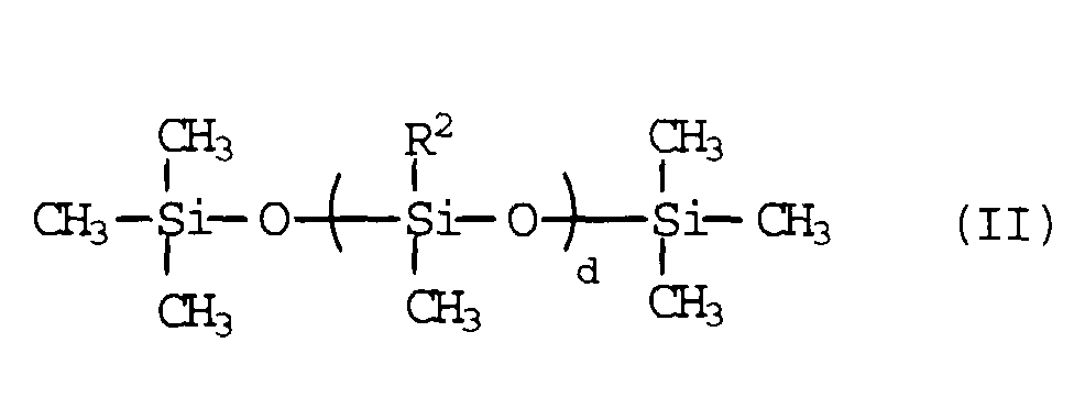
 wherein R7, R8 and R9 are -(-CH2-)q- and may be the same or different; R10 is -OH, -COOH, -CH=CH2, -C(CH3)=CH2 or -(-CH2-)r-CH3; R11 is -(-CH2-)s-CH3; n and q are an integer of 1 to 15; r and s are an integer of 0 to 15; e' is an integer of 1 to 50; and f' is an integer of 1 to 300; or
 wherein R12 is -(-CH2-)v-; v is an integer of 1 to 15; t is an integer of 1 to 50; and u is an integer of 1 to 300.
