EP1101686A1 - Telescoping joint assembly and a method for making the same - Google Patents
Telescoping joint assembly and a method for making the same Download PDFInfo
- Publication number
- EP1101686A1 EP1101686A1 EP00309562A EP00309562A EP1101686A1 EP 1101686 A1 EP1101686 A1 EP 1101686A1 EP 00309562 A EP00309562 A EP 00309562A EP 00309562 A EP00309562 A EP 00309562A EP 1101686 A1 EP1101686 A1 EP 1101686A1
- Authority
- EP
- European Patent Office
- Prior art keywords
- cavity
- joint assembly
- telescoping joint
- members
- telescoping
- Prior art date
- Legal status (The legal status is an assumption and is not a legal conclusion. Google has not performed a legal analysis and makes no representation as to the accuracy of the status listed.)
- Withdrawn
Links
- 238000000034 method Methods 0.000 title claims abstract description 11
- 239000000463 material Substances 0.000 claims description 49
- 239000012815 thermoplastic material Substances 0.000 claims description 8
- 238000004519 manufacturing process Methods 0.000 claims description 6
- 238000010438 heat treatment Methods 0.000 claims description 4
- 230000007423 decrease Effects 0.000 claims description 3
- 238000007373 indentation Methods 0.000 claims description 3
- 239000004677 Nylon Substances 0.000 claims description 2
- DHKHKXVYLBGOIT-UHFFFAOYSA-N acetaldehyde Diethyl Acetal Natural products CCOC(C)OCC DHKHKXVYLBGOIT-UHFFFAOYSA-N 0.000 claims description 2
- 125000002777 acetyl group Chemical class [H]C([H])([H])C(*)=O 0.000 claims description 2
- 238000001816 cooling Methods 0.000 claims description 2
- 229920001778 nylon Polymers 0.000 claims description 2
- 238000007711 solidification Methods 0.000 claims description 2
- 230000008023 solidification Effects 0.000 claims description 2
- 229920001187 thermosetting polymer Polymers 0.000 claims 2
- 239000011261 inert gas Substances 0.000 abstract description 9
- 230000033001 locomotion Effects 0.000 abstract description 8
- 239000002861 polymer material Substances 0.000 abstract description 3
- 239000004033 plastic Substances 0.000 abstract description 2
- 230000000712 assembly Effects 0.000 description 10
- 238000000429 assembly Methods 0.000 description 10
- 230000008878 coupling Effects 0.000 description 6
- 238000010168 coupling process Methods 0.000 description 6
- 238000005859 coupling reaction Methods 0.000 description 6
- 230000008901 benefit Effects 0.000 description 4
- 238000003754 machining Methods 0.000 description 4
- 239000000725 suspension Substances 0.000 description 3
- XKRFYHLGVUSROY-UHFFFAOYSA-N Argon Chemical compound [Ar] XKRFYHLGVUSROY-UHFFFAOYSA-N 0.000 description 2
- 230000005540 biological transmission Effects 0.000 description 2
- 239000007789 gas Substances 0.000 description 2
- 230000006698 induction Effects 0.000 description 2
- 238000002844 melting Methods 0.000 description 2
- 230000008018 melting Effects 0.000 description 2
- 239000007787 solid Substances 0.000 description 2
- 208000027418 Wounds and injury Diseases 0.000 description 1
- 229910052786 argon Inorganic materials 0.000 description 1
- 230000015572 biosynthetic process Effects 0.000 description 1
- 238000005266 casting Methods 0.000 description 1
- 230000015556 catabolic process Effects 0.000 description 1
- 230000006378 damage Effects 0.000 description 1
- 238000006731 degradation reaction Methods 0.000 description 1
- 230000003292 diminished effect Effects 0.000 description 1
- 229920001971 elastomer Polymers 0.000 description 1
- 239000004519 grease Substances 0.000 description 1
- 208000014674 injury Diseases 0.000 description 1
- 238000003780 insertion Methods 0.000 description 1
- 230000037431 insertion Effects 0.000 description 1
- 239000007788 liquid Substances 0.000 description 1
- 239000000314 lubricant Substances 0.000 description 1
- 230000013011 mating Effects 0.000 description 1
- 239000002184 metal Substances 0.000 description 1
- 238000012986 modification Methods 0.000 description 1
- 230000004048 modification Effects 0.000 description 1
- 229920005989 resin Polymers 0.000 description 1
- 239000011347 resin Substances 0.000 description 1
- 239000005060 rubber Substances 0.000 description 1
- 238000004513 sizing Methods 0.000 description 1
Images




Classifications
-
- B—PERFORMING OPERATIONS; TRANSPORTING
- B62—LAND VEHICLES FOR TRAVELLING OTHERWISE THAN ON RAILS
- B62D—MOTOR VEHICLES; TRAILERS
- B62D1/00—Steering controls, i.e. means for initiating a change of direction of the vehicle
- B62D1/02—Steering controls, i.e. means for initiating a change of direction of the vehicle vehicle-mounted
- B62D1/16—Steering columns
- B62D1/18—Steering columns yieldable or adjustable, e.g. tiltable
- B62D1/185—Steering columns yieldable or adjustable, e.g. tiltable adjustable by axial displacement, e.g. telescopically
-
- F—MECHANICAL ENGINEERING; LIGHTING; HEATING; WEAPONS; BLASTING
- F16—ENGINEERING ELEMENTS AND UNITS; GENERAL MEASURES FOR PRODUCING AND MAINTAINING EFFECTIVE FUNCTIONING OF MACHINES OR INSTALLATIONS; THERMAL INSULATION IN GENERAL
- F16C—SHAFTS; FLEXIBLE SHAFTS; ELEMENTS OR CRANKSHAFT MECHANISMS; ROTARY BODIES OTHER THAN GEARING ELEMENTS; BEARINGS
- F16C29/00—Bearings for parts moving only linearly
- F16C29/02—Sliding-contact bearings
-
- F—MECHANICAL ENGINEERING; LIGHTING; HEATING; WEAPONS; BLASTING
- F16—ENGINEERING ELEMENTS AND UNITS; GENERAL MEASURES FOR PRODUCING AND MAINTAINING EFFECTIVE FUNCTIONING OF MACHINES OR INSTALLATIONS; THERMAL INSULATION IN GENERAL
- F16C—SHAFTS; FLEXIBLE SHAFTS; ELEMENTS OR CRANKSHAFT MECHANISMS; ROTARY BODIES OTHER THAN GEARING ELEMENTS; BEARINGS
- F16C2326/00—Articles relating to transporting
- F16C2326/20—Land vehicles
- F16C2326/24—Steering systems, e.g. steering rods or columns
-
- Y—GENERAL TAGGING OF NEW TECHNOLOGICAL DEVELOPMENTS; GENERAL TAGGING OF CROSS-SECTIONAL TECHNOLOGIES SPANNING OVER SEVERAL SECTIONS OF THE IPC; TECHNICAL SUBJECTS COVERED BY FORMER USPC CROSS-REFERENCE ART COLLECTIONS [XRACs] AND DIGESTS
- Y10—TECHNICAL SUBJECTS COVERED BY FORMER USPC
- Y10T—TECHNICAL SUBJECTS COVERED BY FORMER US CLASSIFICATION
- Y10T29/00—Metal working
- Y10T29/49—Method of mechanical manufacture
- Y10T29/49616—Structural member making
- Y10T29/49622—Vehicular structural member making
-
- Y—GENERAL TAGGING OF NEW TECHNOLOGICAL DEVELOPMENTS; GENERAL TAGGING OF CROSS-SECTIONAL TECHNOLOGIES SPANNING OVER SEVERAL SECTIONS OF THE IPC; TECHNICAL SUBJECTS COVERED BY FORMER USPC CROSS-REFERENCE ART COLLECTIONS [XRACs] AND DIGESTS
- Y10—TECHNICAL SUBJECTS COVERED BY FORMER USPC
- Y10T—TECHNICAL SUBJECTS COVERED BY FORMER US CLASSIFICATION
- Y10T29/00—Metal working
- Y10T29/49—Method of mechanical manufacture
- Y10T29/49636—Process for making bearing or component thereof
- Y10T29/49641—Linear bearing
-
- Y—GENERAL TAGGING OF NEW TECHNOLOGICAL DEVELOPMENTS; GENERAL TAGGING OF CROSS-SECTIONAL TECHNOLOGIES SPANNING OVER SEVERAL SECTIONS OF THE IPC; TECHNICAL SUBJECTS COVERED BY FORMER USPC CROSS-REFERENCE ART COLLECTIONS [XRACs] AND DIGESTS
- Y10—TECHNICAL SUBJECTS COVERED BY FORMER USPC
- Y10T—TECHNICAL SUBJECTS COVERED BY FORMER US CLASSIFICATION
- Y10T29/00—Metal working
- Y10T29/49—Method of mechanical manufacture
- Y10T29/49826—Assembling or joining
- Y10T29/49885—Assembling or joining with coating before or during assembling
-
- Y—GENERAL TAGGING OF NEW TECHNOLOGICAL DEVELOPMENTS; GENERAL TAGGING OF CROSS-SECTIONAL TECHNOLOGIES SPANNING OVER SEVERAL SECTIONS OF THE IPC; TECHNICAL SUBJECTS COVERED BY FORMER USPC CROSS-REFERENCE ART COLLECTIONS [XRACs] AND DIGESTS
- Y10—TECHNICAL SUBJECTS COVERED BY FORMER USPC
- Y10T—TECHNICAL SUBJECTS COVERED BY FORMER US CLASSIFICATION
- Y10T29/00—Metal working
- Y10T29/53—Means to assemble or disassemble
- Y10T29/53096—Means to assemble or disassemble including means to provide a controlled environment
-
- Y—GENERAL TAGGING OF NEW TECHNOLOGICAL DEVELOPMENTS; GENERAL TAGGING OF CROSS-SECTIONAL TECHNOLOGIES SPANNING OVER SEVERAL SECTIONS OF THE IPC; TECHNICAL SUBJECTS COVERED BY FORMER USPC CROSS-REFERENCE ART COLLECTIONS [XRACs] AND DIGESTS
- Y10—TECHNICAL SUBJECTS COVERED BY FORMER USPC
- Y10T—TECHNICAL SUBJECTS COVERED BY FORMER US CLASSIFICATION
- Y10T403/00—Joints and connections
- Y10T403/32—Articulated members
- Y10T403/32254—Lockable at fixed position
- Y10T403/32467—Telescoping members
Definitions
- This invention relates to a joint assembly and a method for making a joint assembly, and more particularly to a telescoping joint assembly and a method for making a telescoping joint assembly having a pair of members which telescopingly co-operate to form a relatively tight and reliable joint.
- Automotive vehicles and other types of assemblies often utilise telescoping type joints and/or joint assemblies to operatively couple selectively rotatable shafts or members in a manner which allows torque or rotational energy to be communicated and/or transmitted by and between the coupled members, while concomitantly allowing the coupled members to independently move axially with respect to each other (e.g., to selectively move "toward and away” from each other).
- a vehicle steering system or assembly generally includes a steering shaft or column and a telescoping intermediate shaft which is coupled to and transfers torque between a steering column and a steering gear assembly. Particularly, the rotational energy of the steering column is transferred through the telescoping intermediate shaft to the gear assembly and the wheel suspension assembly, thereby allowing the vehicle to be selectively steered.
- the intermediate shaft comprises and/or includes an inner shaft or member and an outer shaft or member which movably and selectively receives and/or “mates” with the inner shaft or member and which co-operates with the inner member to allow the steering column and gear shaft to be “axially compliant” (i.e., to selectively and independently move “toward and away” from each other).
- the inner member is typically coated or lined with a resin, rubber or polymer material, or contains a bearing assembly.
- the telescoping intermediate shaft compensates for the relative movement between the vehicle body and vehicle frame which occurs as the car is driven and allows at least one of the coupled members, such as the steering column, to substantially and desirably "collapse" in the event of a collision or accident, thereby substantially reducing the probability of injury to the driver.
- the telescoping shaft may further allow the steering column to be adjusted by the driver in an axial or telescopic manner.
- these prior joint assemblies are typically relatively loose fitting and do not have a relatively precise fit or "correspondence" between the telescoping members and/or between one or more of the telescoping members and the liner or bearing assembly.
- the members and the liner/bearing assembly are each formed by separate and independent processes, the manufacturing "tolerance” associated with each of the members and the liner/bearing assembly are additively accumulated or "stacked", thereby resulting in a relatively "loose” overall tolerance and a relatively imprecise or relatively loose fit.
- these prior telescoping joint assemblies suffer from undesirable "slop", “lash”, vibration, frictional loss, and/or “frictional lock-up", which require relatively costly and complicated modifications.
- these undesirable attributes hinder and/or undesirably diminish the sliding engagement between the telescoping members, resulting in an inefficient transmission of torque or rotational energy while concomitantly creating excessive wear and fatigue to and of the telescoping members, thereby causing failure and/or diminished performance (e.g., undesirably allowing vibrational forces and/or other movements/forces to be readily transferred between the coupled components and/or members, such as between the wheel suspension assembly and the steering column).
- Efforts to improve these relatively loose joints typically include but are not limited to relatively costly sizing, adjusting, or machining of the respective shafts. Furthermore, in order to obtain a more precise tolerance or fit between the inner and outer members, the members must typically undergo relatively complex and undesirable machining processes after they have been formed and/or after a lining has been applied to the inner and/or outer member. This "post-fabrication" machining undesirably increases the expense, time, and difficulty of the manufacturing process.
- a telescoping joint assembly includes a first member having an inner cavity; a second member which is selectively and movably disposed within the cavity and which co-operates with the first member to form a gap; a certain amount of a thermoplastic material which is disposed within the gap and which selectively shrinks and solidifies, thereby bonding to the second member and allowing the second member to be slidably disposed within the cavity.
- a method for making a telescoping joint assembly includes the steps of providing a first member having a cavity of a first shape; providing a second member adapted to be inserted within the cavity; placing an amount of thermoplastic material within the cavity; heating the cavity effective to liquefy the thermoplastic material; heating the second member; inserting the heated second member within the cavity, effective to cause the thermoplastic material to be distributed within the cavity and around the second member; cooling the first member effective to solidify the material, thereby bonding the material onto the second member and creating a telescoping joint assembly.
- a telescoping joint assembly embodying the invention selectively allows torque and/or rotational energy to be transmitted and/or communicated between two telescoping members, while concomitantly allowing the telescoping members to selectively, independently, and reciprocally move toward and away from each other.
- a telescoping joint assembly embodying the invention substantially eliminates and/or reduces "slop”, “lash”, frictional losses and/or “frictional lock-up”, and substantially eliminates and/or reduces the amount of vibrational forces transferred between the coupled members.
- the joint assembly 10 includes an inner shaft or member 12 which is adapted to be selectively, operatively and slidably inserted into and to selectively engage a generally hollow or tubular outer shaft or member 14.
- Assembly 10 further includes a resinous, plastic or polymer material 16 which is inserted into member 14 and which, as explained more fully below, coats or lines the inner shaft 12, thereby providing a relatively durable and low friction bearing or surface 18 which is effective to promote and/or assist the telescopic sliding motion between the members 12, 14 in manner which is more fully delineated below.
- member 12 includes an outer surface 20, which is coated, lined or covered by material 16, as best shown in Figures 4 - 6.
- surface 20 has a generally oblong cross sectional shape which is co-operatively formed by two opposing substantially flat surface portions 22, 24 which are integrally formed with and which terminate upon opposed generally convex and semi-circular surface portions 26, 28.
- Surface 20 includes a knurled or raised projection, protuberance, or formation 30 which protrudes and/or outwardly projects from surface 20 and which, as described more fully and completely below, is adapted to selectively engage the solidified material 16, thereby securing the material to member 12.
- projection 30 comprises one or more indentations, grooves or openings disposed upon and/or within surface 20 and which are each effective to "hold” or secure at least a portion of the solidified material 16 onto surface 20, thereby securing at least a portion of the solidified material 16 to member 12.
- Member 14 further includes and/or forms a cavity 34 which is bounded by and/or is defined by an inner surface 32.
- Cavity 34 has a generally oblong cross sectional shape which is substantially and integrally formed by two opposing substantially flat surface portions 36, 38 which are integrally formed with and which terminate upon two opposed, concave, and semi-circular surface portions 40, 42.
- surface 20 and surface 32 have substantially similar and corresponding shapes with the exception that surface 32 is relatively larger in size and/or surface area than surface 20. Hence, when inner member 12 is inserted into cavity 34, a substantially uniform distance or gap 44 is formed between surface 20 and surface 32.
- the distance or gap 44 between surfaces 20 and 32 is substantially uniform.
- surfaces 20 and 32 each include a plurality of conventional and corresponding "splines" which are circumferentially formed upon the respective surfaces 20, 32 and which are adapted to selectively and co-operatively intermesh.
- material 16 substantially and uniformly coats or lines the portion of member 12 which telescopically penetrates cavity 34 and/or engages member 14.
- Material 16 is resinous and/or polymeric in nature and, in one non-limiting embodiment of the invention, comprises thermoplastic material such as acetal, 6:6 nylon material. As discussed more fully and completely below, once assembly 10 is fully assembled and/or formed, material 16 substantially and uniformly occupies or resides within gap 44.
- the outer surface 18 of the solidified material 16 is substantially similar in shape to surfaces 20 and 32 with the exception that surface 18 is relatively larger in size and/or has a relatively larger surface area than does surface 20 and is relatively smaller in size and/or has a relatively smaller surface area than does surface 32.
- a substantially uniform distance or gap 48 is formed between surfaces 18 and 32.
- the gap 48 between surfaces 18 and 32 is relatively small, thereby providing a considerably precise fit between the engaging portions of members 12 and 14.
- the distance or gap 48 between surfaces 18 and 32 is substantially uniform and equal to about 0.03 inches.
- This relatively minute gap 48 substantially prevents members 12 and 14 from independently rotating with respect to each other, thereby allowing joint assembly 10 to effectively transmit torque between the selectively coupled members 12 and 14.
- This relatively small distance 48 and precise "dimensional fit" between material 16 and outer member 14 further substantially eliminates “lash” and vibration and improves the overall operational "smoothness" of assembly 10.
- This relatively minute gap or distance 48 is created through the novel method of assembling and/or fabricating joint assembly 10. As best shown in Figures 1-5, assembly 10 is assembled and/or fabricated as follows.
- Member 14 is initially inserted into a fixture 56, which secures member 14 in a substantially "upright” position.
- Cavity 34 is then filled or "flooded” with an inert gas (e.g., the air and/or other gasses resident within cavity 34 are forcibly and intentionally replaced with an inert gas).
- member 12 and 14 may also be immersed within the inert gas or the gas filled cavity 34.
- the inert gas comprises argon gas, although other inert gasses may be utilised. The presence of the inert gas within cavity 34 substantially prevents the metal of members 12, 14 from oxidising, and further substantially prevents degradation of material 16.
- the entire assembly and/or fabrication process is performed within an inert gas environment, thereby causing substantially the entire surface 32 of member 12 and surface 20 of member 14 to be selectively exposed to the inert gas.
- Members 12 and 14 are then each respectively heated by the use of conventional heat induction coils 50, 52. Particularly, members 12, 14 are heated until they reach a predetermined temperature which is substantially greater than the melting point of material 16.
- cavity 34 is filled with the inert gas and the members 12, 14 are heated, a predetermined amount of material 16 is placed within cavity 34, as best shown in Figure 2.
- material 16 is melted or liquefied prior to its insertion within cavity 34.
- material 16 may be placed within cavity 34 in a substantial "solid form” or “solid state” and subsequently melted within the cavity 34 by the use of heat induction from coil 52 and member 14. Member 12 is then gradually inserted into cavity 34.
- material 16 Since the temperature of members 12, 14 is above the melting point of the material 16, as member 12 is inserted into cavity 34, material 16 remains in its liquid or molten state and is displaced around the outer surface of member 12 as the member 12 is inserted into cavity 34. Particularly, as shown best in Figure 3, when member 12 is fully inserted into cavity 34, material 16 substantially fills the gap 44 formed between the outer surface 20 of member 12 and the inner surface 32 of member 14.
- the liquefied material 16 is substantially and evenly distributed between surfaces 20 and 32.
- the heat provided by coil 52 is then selectively removed or "lowered", thereby allowing heat to dissipate from assembly 10 and reducing the temperature of members 12, 14 and material 16.
- the material 16 begins to solidify and/or harden.
- the solidification of material 16 causes the material 16 to shrink or decrease in size by a predetermined and relatively highly predictable amount, and further causes the material 16 to bond or attach to member 12.
- the relatively small, uniform and precise gap 48 is formed, thereby providing a highly precise mating between members 12 and 14.
- the gap 48 is determined solely by the relatively highly predictable, uniform and controlled shrinkage of material 16.
- the present invention substantially avoids the "tolerance stacking" associated with prior art telescoping joint assemblies.
- projection 30 secures material 16 to member 12.
- member 12 is removed from cavity 34 and a conventional and commercially available lubricant, such as grease or oil, may be selectively applied to the outer surface 18 of solidified material 16 and/or to the inner surface 32 of member 14 in order to reduce sliding type friction between the engaged members 12, 14.
- a conventional and commercially available lubricant such as grease or oil
- joint assembly 10 replaces the traditional and previously delineated telescoping intermediate and/or steering shaft which is resident within a vehicle steering assembly.
- end 54 of member 12 is operatively attached to the vehicle steering column in a conventional manner and end 56 of member 14 is operatively attached to the vehicle gear shaft or gearbox in a conventional manner.
- the selective torque or rotational energy which is generated by the steering column, is transferred and/or communicated through assembly 10 to the gear shaft in a manner which allows the gear shaft to concomitantly and axially articulate toward and away from the steering column.
- member 12 selectively, telescopically, and movably penetrates member 14 and cavity 34, thereby substantially eliminating the relative torsional motion between member 12 and member 14, and substantially preventing such movement, vibration, lash, or slop from being communicated to the steering column.
- the axial movement provided by assembly 10 also allows the steering column to desirably "collapse" in the event of a collision or accident and/or to be selectively adjusted in a telescoping manner or motion.
- the relatively tightly fitted telescoping members 12 and 14 allow the steering column and the gear shaft to smoothly and consistently articulate, with respect to each other, and substantially reduces and/or eliminates "slop", “lash”, vibration, frictional losses and/or “frictional lock-up” associated with the relatively "loose” tolerances of prior telescoping intermediate shafts and/or steering shaft assemblies.
- assembly 10 may be selectively used within various other applications requiring the coupling of two axially compliant members and the transmission or resistance of torque and/or rotational energy by and between these coupled members. It should further be appreciated that while a pair of shaft type members 12, 14 are shown, assembly 10, as well as the various other coupling assemblies described herein, is adapted to couple other types, shapes, and/or forms or members and to provide the described coupling benefits and/or attributes to these other coupling arrangements.
Landscapes
- Engineering & Computer Science (AREA)
- Mechanical Engineering (AREA)
- General Engineering & Computer Science (AREA)
- Chemical & Material Sciences (AREA)
- Combustion & Propulsion (AREA)
- Transportation (AREA)
- Steering Controls (AREA)
Abstract
A telescoping joint assembly and a method for making a
telescope joint assembly 10. The joint assembly 10 has a
pair of members 12, 14 which are telescopically engaged.
Assembly 10 further includes a resinous, plastic and/or
polymer material 16 which shrinkably coats or lines the
inner shaft 12 after the inner shaft 12 is heated and
exposed to a substantially inert gas, thereby providing a
relatively durable and substantially "low friction" bearing
or surface 18 which is effective to promote and/or assist
the telescopic sliding motion between the members 12, 14.
Description
- This invention relates to a joint assembly and a method for making a joint assembly, and more particularly to a telescoping joint assembly and a method for making a telescoping joint assembly having a pair of members which telescopingly co-operate to form a relatively tight and reliable joint.
- Automotive vehicles and other types of assemblies often utilise telescoping type joints and/or joint assemblies to operatively couple selectively rotatable shafts or members in a manner which allows torque or rotational energy to be communicated and/or transmitted by and between the coupled members, while concomitantly allowing the coupled members to independently move axially with respect to each other (e.g., to selectively move "toward and away" from each other).
- For example and without limitation, a vehicle steering system or assembly generally includes a steering shaft or column and a telescoping intermediate shaft which is coupled to and transfers torque between a steering column and a steering gear assembly. Particularly, the rotational energy of the steering column is transferred through the telescoping intermediate shaft to the gear assembly and the wheel suspension assembly, thereby allowing the vehicle to be selectively steered.
- Typically, the intermediate shaft comprises and/or includes an inner shaft or member and an outer shaft or member which movably and selectively receives and/or "mates" with the inner shaft or member and which co-operates with the inner member to allow the steering column and gear shaft to be "axially compliant" (i.e., to selectively and independently move "toward and away" from each other).
- In order to substantially reduce friction and improve the performance, compliance, and efficiency of this intermediate shaft and/or steering shaft assembly (as well as other types of joint assemblies), the inner member is typically coated or lined with a resin, rubber or polymer material, or contains a bearing assembly. The telescoping intermediate shaft compensates for the relative movement between the vehicle body and vehicle frame which occurs as the car is driven and allows at least one of the coupled members, such as the steering column, to substantially and desirably "collapse" in the event of a collision or accident, thereby substantially reducing the probability of injury to the driver. The telescoping shaft may further allow the steering column to be adjusted by the driver in an axial or telescopic manner.
- Although this intermediate shaft, as well as other substantially similar types of prior joint assemblies, effectively transmit torque between a pair of coupled members or shafts while concomitantly allowing the coupled members to be axially compliant, they suffer from some drawbacks.
- For example and without limitation, these prior joint assemblies are typically relatively loose fitting and do not have a relatively precise fit or "correspondence" between the telescoping members and/or between one or more of the telescoping members and the liner or bearing assembly. Particularly, because the members and the liner/bearing assembly are each formed by separate and independent processes, the manufacturing "tolerance" associated with each of the members and the liner/bearing assembly are additively accumulated or "stacked", thereby resulting in a relatively "loose" overall tolerance and a relatively imprecise or relatively loose fit. As a result, these prior telescoping joint assemblies suffer from undesirable "slop", "lash", vibration, frictional loss, and/or "frictional lock-up", which require relatively costly and complicated modifications.
- Particularly, these undesirable attributes hinder and/or undesirably diminish the sliding engagement between the telescoping members, resulting in an inefficient transmission of torque or rotational energy while concomitantly creating excessive wear and fatigue to and of the telescoping members, thereby causing failure and/or diminished performance (e.g., undesirably allowing vibrational forces and/or other movements/forces to be readily transferred between the coupled components and/or members, such as between the wheel suspension assembly and the steering column).
- Efforts to improve these relatively loose joints typically include but are not limited to relatively costly sizing, adjusting, or machining of the respective shafts. Furthermore, in order to obtain a more precise tolerance or fit between the inner and outer members, the members must typically undergo relatively complex and undesirable machining processes after they have been formed and/or after a lining has been applied to the inner and/or outer member. This "post-fabrication" machining undesirably increases the expense, time, and difficulty of the manufacturing process.
- There is therefore a need to provide a telescoping joint assembly for coupling two members or shafts which overcomes at least some of the various and previously delineated drawbacks of prior coupling assemblies; which allows torque and rotational energy to be relatively efficiently transmitted between the two coupled members or shafts, while concomitantly allowing each of the members or shafts to be axially compliant; which provides for a substantially "tight" fit between the telescoping members; which substantially eliminates and/or reduces "slop", lash, frictional loss, and/or "frictional lock-up"; and which substantially eliminates the need for post-fabrication "machining" of the telescoping members.
- According to a first aspect of the present invention, a telescoping joint assembly is provided. The telescoping joint assembly includes a first member having an inner cavity; a second member which is selectively and movably disposed within the cavity and which co-operates with the first member to form a gap; a certain amount of a thermoplastic material which is disposed within the gap and which selectively shrinks and solidifies, thereby bonding to the second member and allowing the second member to be slidably disposed within the cavity.
- According to a second aspect of the present invention a method for making a telescoping joint assembly is provided. The method includes the steps of providing a first member having a cavity of a first shape; providing a second member adapted to be inserted within the cavity; placing an amount of thermoplastic material within the cavity; heating the cavity effective to liquefy the thermoplastic material; heating the second member; inserting the heated second member within the cavity, effective to cause the thermoplastic material to be distributed within the cavity and around the second member; cooling the first member effective to solidify the material, thereby bonding the material onto the second member and creating a telescoping joint assembly.
- It is an advantage of a telescoping joint assembly embodying the invention that it selectively allows torque and/or rotational energy to be transmitted and/or communicated between two telescoping members, while concomitantly allowing the telescoping members to selectively, independently, and reciprocally move toward and away from each other.
- It is a another advantage of a telescoping joint assembly embodying the invention that it provides substantially "tight" or precise dimensional fit or correspondence between two operatively assembled telescoping members.
- It is a further advantage of a telescoping joint assembly embodying the invention that it substantially eliminates and/or reduces "slop", "lash", frictional losses and/or "frictional lock-up", and substantially eliminates and/or reduces the amount of vibrational forces transferred between the coupled members.
- The present invention will now be described further, by way of example, with reference to the accompanying drawings, in which:
- Figure 1 is a perspective unassembled view of a joint assembly which is made in accordance with the teachings of the preferred embodiment of the invention;
- Figure 2 is a cross sectional view of the joint assembly which is shown in Figure 1 and which is taken along view line 2-2;
- Figure 3 is an enlarged cross sectional view of the joint assembly which is shown in Figure 1, which is taken along the view line 2-2, and which is shown in a partially fabricated state;
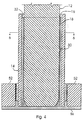
- Figure 4 is an enlarged cross sectional view of the joint assembly which is shown in Figure 1, which is taken along the view line 2-2, and which is shown in a fabricated state;
- Figure 5 is a partial cross sectional view of the joint assembly which is shown in Figure 1, which is taken along the view line 2-2, and which is shown in a fabricated and unassembled state; and
- Figure 6 is an enlarged cross sectional view of the joint assembly which is shown in Figure 4, which is taken along view line 6-6, and which is shown in an assembled state.
-
- Referring now to Figures 1 - 6, there is shown a telescoping
joint assembly 10, which is made in accordance with the teachings of the preferred embodiment of the invention. Thejoint assembly 10 includes an inner shaft ormember 12 which is adapted to be selectively, operatively and slidably inserted into and to selectively engage a generally hollow or tubular outer shaft ormember 14.Assembly 10 further includes a resinous, plastic orpolymer material 16 which is inserted intomember 14 and which, as explained more fully below, coats or lines theinner shaft 12, thereby providing a relatively durable and low friction bearing orsurface 18 which is effective to promote and/or assist the telescopic sliding motion between themembers - In the preferred embodiment of the invention,
member 12 includes anouter surface 20, which is coated, lined or covered bymaterial 16, as best shown in Figures 4 - 6. Particularly, as best shown in Figure 6,surface 20 has a generally oblong cross sectional shape which is co-operatively formed by two opposing substantiallyflat surface portions semi-circular surface portions Surface 20 includes a knurled or raised projection, protuberance, orformation 30 which protrudes and/or outwardly projects fromsurface 20 and which, as described more fully and completely below, is adapted to selectively engage thesolidified material 16, thereby securing the material to member 12. In other alternate embodiments,projection 30 comprises one or more indentations, grooves or openings disposed upon and/or withinsurface 20 and which are each effective to "hold" or secure at least a portion of the solidifiedmaterial 16 ontosurface 20, thereby securing at least a portion of the solidifiedmaterial 16 tomember 12. -
Member 14 further includes and/or forms acavity 34 which is bounded by and/or is defined by aninner surface 32.Cavity 34 has a generally oblong cross sectional shape which is substantially and integrally formed by two opposing substantiallyflat surface portions semi-circular surface portions surface 20 andsurface 32 have substantially similar and corresponding shapes with the exception thatsurface 32 is relatively larger in size and/or surface area thansurface 20. Hence, wheninner member 12 is inserted intocavity 34, a substantially uniform distance orgap 44 is formed betweensurface 20 andsurface 32. In one non-limiting embodiment, the distance orgap 44 betweensurfaces 20 and 32 (i.e., between each of surfaces 22-28 and the respective and opposing surfaces 36-42) is substantially uniform. In alternate embodiments,surfaces respective surfaces - As best shown in Figures 4 through 6,
material 16 substantially and uniformly coats or lines the portion ofmember 12 which telescopically penetratescavity 34 and/or engagesmember 14.Material 16 is resinous and/or polymeric in nature and, in one non-limiting embodiment of the invention, comprises thermoplastic material such as acetal, 6:6 nylon material. As discussed more fully and completely below, onceassembly 10 is fully assembled and/or formed,material 16 substantially and uniformly occupies or resides withingap 44. Theouter surface 18 of thesolidified material 16 is substantially similar in shape tosurfaces surface 18 is relatively larger in size and/or has a relatively larger surface area than doessurface 20 and is relatively smaller in size and/or has a relatively smaller surface area than doessurface 32. Hence, a substantially uniform distance orgap 48 is formed betweensurfaces gap 48 betweensurfaces members gap 48 betweensurfaces minute gap 48 substantially preventsmembers joint assembly 10 to effectively transmit torque between the selectively coupledmembers small distance 48 and precise "dimensional fit" betweenmaterial 16 andouter member 14 further substantially eliminates "lash" and vibration and improves the overall operational "smoothness" ofassembly 10. - This relatively minute gap or
distance 48 is created through the novel method of assembling and/or fabricatingjoint assembly 10. As best shown in Figures 1-5,assembly 10 is assembled and/or fabricated as follows. -
Member 14 is initially inserted into afixture 56, which securesmember 14 in a substantially "upright" position.Cavity 34 is then filled or "flooded" with an inert gas (e.g., the air and/or other gasses resident withincavity 34 are forcibly and intentionally replaced with an inert gas). In another non-limiting embodiment,member cavity 34. In the preferred embodiment of the invention the inert gas comprises argon gas, although other inert gasses may be utilised. The presence of the inert gas withincavity 34 substantially prevents the metal ofmembers material 16. In other alternate embodiments, the entire assembly and/or fabrication process is performed within an inert gas environment, thereby causing substantially theentire surface 32 ofmember 12 andsurface 20 ofmember 14 to be selectively exposed to the inert gas.Members heat induction coils members material 16. - After
cavity 34 is filled with the inert gas and themembers material 16 is placed withincavity 34, as best shown in Figure 2. In the preferred embodiment of the invention,material 16 is melted or liquefied prior to its insertion withincavity 34. However, it should be appreciated thatmaterial 16 may be placed withincavity 34 in a substantial "solid form" or "solid state" and subsequently melted within thecavity 34 by the use of heat induction fromcoil 52 andmember 14.Member 12 is then gradually inserted intocavity 34. - Since the temperature of
members material 16, asmember 12 is inserted intocavity 34,material 16 remains in its liquid or molten state and is displaced around the outer surface ofmember 12 as themember 12 is inserted intocavity 34. Particularly, as shown best in Figure 3, whenmember 12 is fully inserted intocavity 34,material 16 substantially fills thegap 44 formed between theouter surface 20 ofmember 12 and theinner surface 32 ofmember 14. - Once
member 12 has been fully inserted intocavity 34, the liquefiedmaterial 16 is substantially and evenly distributed betweensurfaces coil 52 is then selectively removed or "lowered", thereby allowing heat to dissipate fromassembly 10 and reducing the temperature ofmembers material 16. As the temperature ofmaterial 16 decreases, thematerial 16 begins to solidify and/or harden. The solidification ofmaterial 16 causes thematerial 16 to shrink or decrease in size by a predetermined and relatively highly predictable amount, and further causes thematerial 16 to bond or attach tomember 12. As thematerial 16 solidifies, the relatively small, uniform andprecise gap 48 is formed, thereby providing a highly precise mating betweenmembers material 16 within the engagedmembers gap 48 is determined solely by the relatively highly predictable, uniform and controlled shrinkage ofmaterial 16. As such, the present invention substantially avoids the "tolerance stacking" associated with prior art telescoping joint assemblies. - Once
material 16 has solidified,projection 30 securesmaterial 16 tomember 12. Aftermaterial 16 has solidified and cooled,member 12 is removed fromcavity 34 and a conventional and commercially available lubricant, such as grease or oil, may be selectively applied to theouter surface 18 of solidifiedmaterial 16 and/or to theinner surface 32 ofmember 14 in order to reduce sliding type friction between the engagedmembers - In one non-limiting embodiment,
joint assembly 10 replaces the traditional and previously delineated telescoping intermediate and/or steering shaft which is resident within a vehicle steering assembly. In this configuration, end 54 ofmember 12 is operatively attached to the vehicle steering column in a conventional manner and end 56 ofmember 14 is operatively attached to the vehicle gear shaft or gearbox in a conventional manner. In this manner, the selective torque or rotational energy, which is generated by the steering column, is transferred and/or communicated throughassembly 10 to the gear shaft in a manner which allows the gear shaft to concomitantly and axially articulate toward and away from the steering column. - Particularly, as forces and/or vibrations are imparted upon
assembly 10, by way of the typical wheel suspension assembly,member 12 selectively, telescopically, and movably penetratesmember 14 andcavity 34, thereby substantially eliminating the relative torsional motion betweenmember 12 andmember 14, and substantially preventing such movement, vibration, lash, or slop from being communicated to the steering column. The axial movement provided byassembly 10 also allows the steering column to desirably "collapse" in the event of a collision or accident and/or to be selectively adjusted in a telescoping manner or motion. - Importantly, the relatively tightly fitted
telescoping members - It should be appreciated that the
assembly 10 may be selectively used within various other applications requiring the coupling of two axially compliant members and the transmission or resistance of torque and/or rotational energy by and between these coupled members. It should further be appreciated that while a pair ofshaft type members assembly 10, as well as the various other coupling assemblies described herein, is adapted to couple other types, shapes, and/or forms or members and to provide the described coupling benefits and/or attributes to these other coupling arrangements.
Claims (10)
- A telescoping joint assembly comprising:a first member (14) having an inner cavity (34);a second member (12) which is selectively and movably disposed within the cavity and which co-operates with the first member to form a gap (44); anda thermoplastic material (16) which is disposed within the gap and which selectively shrinks and solidifies, thereby bonding to the second member (12) and allowing the second member (12) to be slidably disposed within the cavity.
- a telescoping joint assembly as claimed in claim 1, wherein said cavity has an oblong shape.
- A telescoping joint assembly as claimed in claim 1 or claim 2, wherein said second member comprises a knurled portion.
- A telescoping joint assembly as claimed in claim 1 or claim 2, wherein said second member comprises an indentation.
- A telescoping joint assembly as claimed in any one of the preceding claims, wherein said material comprises a polymeric material.
- A telescoping joint assembly as claimed in claim 5, wherein said polymeric material comprises 6:6 nylon, acetal or thermoplastic material.
- A telescoping joint comprising: a first member having an inner cavity with a concave surface;a second member having a convex surface which is disposed within said cavity and which is separated from said concave surface by a substantially uniform gap; andan amount of a thermoplastic material disposed within said gap, said material solidifying in response to a decrease in temperature, said solidification of said material effective to bond said material to said convex surface and to shrink said material by a predetermined amount, thereby allowing said second member to be slidably movable within said cavity.
- A telescoping joint assembly as claimed in claim 7, wherein said convex surface includes a protuberance effective to further bond said material to said convex surface.
- A telescoping joint assembly as claimed in claim 7, wherein said convex surface includes an indentation effective to further bond said material to said convex surface.
- A method for manufacturing a telescoping joint assembly, said method comprising the steps of:providing a first member having a cavity of a first shape;providing a second member;heating said first member;placing an amount of liquefied thermosetting material within said cavity;heating said second member;inserting said heated second member within said cavity effective to cause said liquefied thermosetting material to be distributed within said cavity and around said second member; andcooling said first member effective to solidify said material and to shrink said material, thereby bonding said material onto said second member.
Applications Claiming Priority (2)
| Application Number | Priority Date | Filing Date | Title |
|---|---|---|---|
| US443222 | 1999-11-18 | ||
| US09/443,222 US6473968B1 (en) | 1999-11-18 | 1999-11-18 | Telescoping joint assembly and a method for making the same |
Publications (1)
| Publication Number | Publication Date |
|---|---|
| EP1101686A1 true EP1101686A1 (en) | 2001-05-23 |
Family
ID=23759902
Family Applications (1)
| Application Number | Title | Priority Date | Filing Date |
|---|---|---|---|
| EP00309562A Withdrawn EP1101686A1 (en) | 1999-11-18 | 2000-10-30 | Telescoping joint assembly and a method for making the same |
Country Status (2)
| Country | Link |
|---|---|
| US (2) | US6473968B1 (en) |
| EP (1) | EP1101686A1 (en) |
Cited By (2)
| Publication number | Priority date | Publication date | Assignee | Title |
|---|---|---|---|---|
| EP1972523A3 (en) * | 2007-03-21 | 2011-05-04 | GM Global Technology Operations, Inc. | Adjustable steering column utilizing a sleeve and a method of forming a filler with a sleeve |
| US20240392839A1 (en) * | 2023-05-23 | 2024-11-28 | Steering Solutions Ip Holding Corporation | Toothed connection for mating steering sytem components |
Families Citing this family (5)
| Publication number | Priority date | Publication date | Assignee | Title |
|---|---|---|---|---|
| DE69922335T2 (en) * | 1999-02-23 | 2005-12-15 | Matsui Universal Joint Corp. | Drive shaft and method for producing the same |
| US20050200111A1 (en) * | 2004-03-11 | 2005-09-15 | Cymbal William D. | Multi piece bearing for telescoping steering column assembly |
| US7516985B2 (en) * | 2004-03-11 | 2009-04-14 | Delphi Technologies, Inc. | Multi piece bearing for telescoping steering column assembly |
| WO2016007656A1 (en) * | 2014-07-08 | 2016-01-14 | Scinovia, Corp. | Fluid flow rate determinations using velocity vector maps |
| DE102015216326B4 (en) * | 2015-08-26 | 2016-09-08 | Thyssenkrupp Ag | Motor-adjustable steering column for a motor vehicle |
Citations (3)
| Publication number | Priority date | Publication date | Assignee | Title |
|---|---|---|---|---|
| US4033020A (en) * | 1975-08-04 | 1977-07-05 | Trw Inc. | Method of making a slip joint |
| US5243874A (en) * | 1992-02-24 | 1993-09-14 | Pittsburgh Tubular Shafting, Inc. | Method and apparatus for telescopically assembling a pair of elongated members |
| EP0927620A1 (en) * | 1997-12-29 | 1999-07-07 | Volkswagen Aktiengesellschaft | Method for manufacturing a plastic layer |
Family Cites Families (11)
| Publication number | Priority date | Publication date | Assignee | Title |
|---|---|---|---|---|
| GB706795A (en) | 1951-08-03 | 1954-04-07 | Glacier Co Ltd | Improvements in or relating to bearing assemblies |
| US4563912A (en) | 1983-12-19 | 1986-01-14 | Allied Corporation | Telescoping polygonal steering column |
| JP2832934B2 (en) | 1987-08-22 | 1998-12-09 | アイシン精機株式会社 | Method of manufacturing telescopic shaft |
| US5042153A (en) * | 1988-02-16 | 1991-08-27 | Toyota Jidosha Kabushiki Kaisha | Method for producing a sliding part |
| AU630941B2 (en) | 1989-04-10 | 1992-11-12 | Mitsubishi Chemical Corporation | A method for producing a sliding coupling by a monomer casting method |
| JPH02307710A (en) * | 1989-05-23 | 1990-12-20 | Aisin Seiki Co Ltd | Telescopic shaft having formed resin layer |
| JP2935950B2 (en) * | 1993-12-03 | 1999-08-16 | 株式会社山田製作所 | Steering shaft and apparatus for manufacturing the same |
| US5444911A (en) * | 1994-05-05 | 1995-08-29 | Chromalloy Gas Turbine Corporation | Gas turbine engine vane assembly repair |
| US5720102A (en) * | 1995-01-27 | 1998-02-24 | Dana Corporation | Method for making a drive line slip joint assembly |
| JP3004590B2 (en) * | 1996-08-02 | 2000-01-31 | 株式会社山田製作所 | Steering shaft |
| US5722300A (en) * | 1996-08-16 | 1998-03-03 | General Motors Corporation | Motor vehicle steering column |
-
1999
- 1999-11-18 US US09/443,222 patent/US6473968B1/en not_active Expired - Fee Related
-
2000
- 2000-10-30 EP EP00309562A patent/EP1101686A1/en not_active Withdrawn
-
2002
- 2002-07-09 US US10/191,818 patent/US20030026644A1/en not_active Abandoned
Patent Citations (3)
| Publication number | Priority date | Publication date | Assignee | Title |
|---|---|---|---|---|
| US4033020A (en) * | 1975-08-04 | 1977-07-05 | Trw Inc. | Method of making a slip joint |
| US5243874A (en) * | 1992-02-24 | 1993-09-14 | Pittsburgh Tubular Shafting, Inc. | Method and apparatus for telescopically assembling a pair of elongated members |
| EP0927620A1 (en) * | 1997-12-29 | 1999-07-07 | Volkswagen Aktiengesellschaft | Method for manufacturing a plastic layer |
Non-Patent Citations (1)
| Title |
|---|
| PATENT ABSTRACTS OF JAPAN vol. 013, no. 247 (M - 835) 8 June 1989 (1989-06-08) * |
Cited By (5)
| Publication number | Priority date | Publication date | Assignee | Title |
|---|---|---|---|---|
| EP1972523A3 (en) * | 2007-03-21 | 2011-05-04 | GM Global Technology Operations, Inc. | Adjustable steering column utilizing a sleeve and a method of forming a filler with a sleeve |
| US8092635B2 (en) | 2007-03-21 | 2012-01-10 | Nexteer (Beijing) Technology Co., Ltd. | Adjustable steering column utilizing a sleeve and a method of forming a filler with a sleeve |
| US8448987B2 (en) | 2007-03-21 | 2013-05-28 | Steering Solutions Ip Holding Corporation | Adjustable steering column utilizing a sleeve and a method of forming a filler with a sleeve |
| US20240392839A1 (en) * | 2023-05-23 | 2024-11-28 | Steering Solutions Ip Holding Corporation | Toothed connection for mating steering sytem components |
| US12486873B2 (en) * | 2023-05-23 | 2025-12-02 | Steering Solutions Ip Holding Corporation | Toothed connection for mating steering system components |
Also Published As
| Publication number | Publication date |
|---|---|
| US20030026644A1 (en) | 2003-02-06 |
| US6473968B1 (en) | 2002-11-05 |
Similar Documents
| Publication | Publication Date | Title |
|---|---|---|
| US5243874A (en) | Method and apparatus for telescopically assembling a pair of elongated members | |
| US6761503B2 (en) | Splined member for use in a slip joint and method of manufacturing the same | |
| CA2167771C (en) | Method for making a drive line slip joint assembly | |
| US6026704A (en) | Steering shaft | |
| JP2863114B2 (en) | Drive shaft with rush member | |
| EP2281731B1 (en) | Spline telescopic shaft, method for manufacturing spline telescopic shaft, and vehicle steering apparatus | |
| EP0705990B1 (en) | Spherical joint and process for manufacturing the same | |
| EP0138896B1 (en) | Composite shafts | |
| US20020032065A1 (en) | Propeller shaft and method for producing the same | |
| US6473968B1 (en) | Telescoping joint assembly and a method for making the same | |
| US6368225B1 (en) | Axially collapsible driveshaft assembly and method of manufacturing same | |
| JP2013227018A (en) | Method of manufacturing steering column | |
| MXPA96002233A (en) | Composite encased ball joint | |
| WO2009002992A2 (en) | Ball-and-socket joint ball pin with injection molded metal ball | |
| EP0893613B1 (en) | Cardan shaft | |
| JP2017025964A (en) | Telescopic shaft and manufacturing method thereof | |
| US6634078B1 (en) | Method of manufacturing a splined member for use in a slip joint | |
| JP2011174607A (en) | Spline machining method and spline shaft | |
| EP1828630A2 (en) | A universal joint assembly for an automotive driveline system | |
| EP1031747B1 (en) | Driving Shaft and method for producing the same | |
| EP1759955B1 (en) | Bush, particularly for vehicle steering column | |
| US20030004001A1 (en) | Simplified driveline | |
| US5906543A (en) | Low or no-lash slider shaft for a steering column | |
| CN111661138A (en) | Method for manufacturing spline telescopic shaft and spline telescopic shaft | |
| CN105313950A (en) | Electric power steering system |
Legal Events
| Date | Code | Title | Description |
|---|---|---|---|
| PUAI | Public reference made under article 153(3) epc to a published international application that has entered the european phase |
Free format text: ORIGINAL CODE: 0009012 |
|
| AK | Designated contracting states |
Kind code of ref document: A1 Designated state(s): DE FR GB |
|
| AX | Request for extension of the european patent |
Free format text: AL;LT;LV;MK;RO;SI |
|
| 17P | Request for examination filed |
Effective date: 20011017 |
|
| 17Q | First examination report despatched |
Effective date: 20011224 |
|
| AKX | Designation fees paid |
Free format text: DE FR GB |
|
| STAA | Information on the status of an ep patent application or granted ep patent |
Free format text: STATUS: THE APPLICATION IS DEEMED TO BE WITHDRAWN |
|
| 18D | Application deemed to be withdrawn |
Effective date: 20020708 |