EP1101472A2 - Applicator for tampons - Google Patents
Applicator for tampons Download PDFInfo
- Publication number
- EP1101472A2 EP1101472A2 EP00310300A EP00310300A EP1101472A2 EP 1101472 A2 EP1101472 A2 EP 1101472A2 EP 00310300 A EP00310300 A EP 00310300A EP 00310300 A EP00310300 A EP 00310300A EP 1101472 A2 EP1101472 A2 EP 1101472A2
- Authority
- EP
- European Patent Office
- Prior art keywords
- tampon
- inner cylinder
- applicator
- outer cylinder
- set forth
- Prior art date
- Legal status (The legal status is an assumption and is not a legal conclusion. Google has not performed a legal analysis and makes no representation as to the accuracy of the status listed.)
- Granted
Links
- 239000000463 material Substances 0.000 claims abstract description 18
- 229920005992 thermoplastic resin Polymers 0.000 claims abstract description 10
- 238000001746 injection moulding Methods 0.000 description 10
- 229920005989 resin Polymers 0.000 description 9
- 239000011347 resin Substances 0.000 description 9
- 238000004519 manufacturing process Methods 0.000 description 7
- 241001503991 Consolida Species 0.000 description 4
- 238000000034 method Methods 0.000 description 4
- 239000004698 Polyethylene Substances 0.000 description 3
- 239000004743 Polypropylene Substances 0.000 description 3
- 238000000465 moulding Methods 0.000 description 3
- -1 polyethylene Polymers 0.000 description 3
- 238000010586 diagram Methods 0.000 description 2
- 238000010438 heat treatment Methods 0.000 description 2
- 229920001684 low density polyethylene Polymers 0.000 description 2
- 239000004702 low-density polyethylene Substances 0.000 description 2
- 229920000139 polyethylene terephthalate Polymers 0.000 description 2
- 239000005020 polyethylene terephthalate Substances 0.000 description 2
- 239000010902 straw Substances 0.000 description 2
- 229920003002 synthetic resin Polymers 0.000 description 2
- 239000000057 synthetic resin Substances 0.000 description 2
- 229920000742 Cotton Polymers 0.000 description 1
- 241000219146 Gossypium Species 0.000 description 1
- 239000000498 cooling water Substances 0.000 description 1
- 238000001125 extrusion Methods 0.000 description 1
- 239000000835 fiber Substances 0.000 description 1
- 239000000155 melt Substances 0.000 description 1
- 238000012986 modification Methods 0.000 description 1
- 230000004048 modification Effects 0.000 description 1
- 229920000573 polyethylene Polymers 0.000 description 1
- 229920001155 polypropylene Polymers 0.000 description 1
Images


Classifications
-
- A—HUMAN NECESSITIES
- A61—MEDICAL OR VETERINARY SCIENCE; HYGIENE
- A61F—FILTERS IMPLANTABLE INTO BLOOD VESSELS; PROSTHESES; DEVICES PROVIDING PATENCY TO, OR PREVENTING COLLAPSING OF, TUBULAR STRUCTURES OF THE BODY, e.g. STENTS; ORTHOPAEDIC, NURSING OR CONTRACEPTIVE DEVICES; FOMENTATION; TREATMENT OR PROTECTION OF EYES OR EARS; BANDAGES, DRESSINGS OR ABSORBENT PADS; FIRST-AID KITS
- A61F13/00—Bandages or dressings; Absorbent pads
- A61F13/15—Absorbent pads, e.g. sanitary towels, swabs or tampons for external or internal application to the body; Supporting or fastening means therefor; Tampon applicators
- A61F13/20—Tampons, e.g. catamenial tampons; Accessories therefor
- A61F13/26—Means for inserting tampons, i.e. applicators
-
- A—HUMAN NECESSITIES
- A61—MEDICAL OR VETERINARY SCIENCE; HYGIENE
- A61F—FILTERS IMPLANTABLE INTO BLOOD VESSELS; PROSTHESES; DEVICES PROVIDING PATENCY TO, OR PREVENTING COLLAPSING OF, TUBULAR STRUCTURES OF THE BODY, e.g. STENTS; ORTHOPAEDIC, NURSING OR CONTRACEPTIVE DEVICES; FOMENTATION; TREATMENT OR PROTECTION OF EYES OR EARS; BANDAGES, DRESSINGS OR ABSORBENT PADS; FIRST-AID KITS
- A61F13/00—Bandages or dressings; Absorbent pads
- A61F13/15—Absorbent pads, e.g. sanitary towels, swabs or tampons for external or internal application to the body; Supporting or fastening means therefor; Tampon applicators
- A61F13/20—Tampons, e.g. catamenial tampons; Accessories therefor
Definitions
- the present invention relates to a tampon applicator to be employed when a sanitary tampon is to be inserted into a human body.
- the applicator for the sanitary tampon is constructed to include an outer cylinder for fitting the tampon therein, and an inner cylinder inserted into the outer cylinder and protruding rearwardly from the root end of the outer cylinder.
- a take-out cord, as extended from the tampon, is led out of the outer cylinder through the inner cylinder and protruded rearwardly from a rear end of the inner cylinder.
- the outer cylinder When the tampon is to be employed, the outer cylinder is inserted into a vaginal cavity, and the inner cylinder is pushed to push the tampon out of the outer cylinder. Then, the tampon is inserted into the vaginal cavity while expanding a number of deformable valves at the leading end of the outer cylinder.
- Some of the existing applicators are formed to have an outer cylinder and an inner cylinder which are made of paper.
- an outer cylinder injection-molded of a synthetic resin has been employed so that it may have a smooth surface and may be smoothly inserted into the vaginal cavity.
- the inner cylinder is also generally formed by the injection-molding method.
- the inner cylinder of the applicator takes a high molding cost if it is injection-molded of a synthetic resin, because the mold to be employed for the injection molding is expensive.
- the mold has to be remade to increase the cost for this design change.
- the tampon applicator is dumped after use, it is preferable for the environment to minimize the amount of resin to be employed. Accordingly, by making at least the inner cylinder thin and diametrically small, it is possible to reduce the amount of resin to be employed.
- the injection-molding method cannot realize the thin, diametrically small inner cylinder, because of the following reasons:
- the invention has an object to provide a tampon applicator which can manufacture the inner cylinder at low cost, can enhance the buckling strength in the axial direction even when the inner cylinder is made thin and diametrically small, and can easily deform the shape of the inner cylinder according to the change in the shape of the outer cylinder.
- an applicator for a tampon may comprise: an outer cylinder including a protruding mouth at a leading end thereof, through which a tampon is pushed out and an opening at a root end thereof; and an inner cylinder for pushing out the tampon which has a front end located in the outer cylinder arid a rear end protruding rearwardly from the outer cylinder through the opening, wherein the inner cylinder is formed of an extruded material which is extrusion-molded of a thermoplastic resin into a cylindrical shape, and is provided at the front end thereof with a push portion which is deformed to have a larger diameter from the extruded material.
- the outer cylinder includes a large diameter portion for fitting the tampon therein, and a small diameter portion extending from the large diameter portion toward the root end, and wherein the push portion of the inner cylinder is positioned in the large diameter portion and has a larger external diameter than an internal diameter of the small diameter portion.
- the inner cylinder of the applicator is made of the excluded material of the thermoplastic resin so that the cost for manufacturing the inner cylinder can be lowered.
- the extruded material can freely select the thickness and the external diameter in comparison with the injection-molding, so that the thin, diametrically small inner cylinder can be formed with a smaller amount of employed resin.
- the inner cylinder made of the extruded material of the thermoplastic resin can be easily formed with the diverging push portion at the front end which is located within the outer cylinder.
- the extruded material is extrusion-molded and then axially oriented.
- the resin is oriented in the axial direction of the inner cylinder, the axial strength of the inner cylinder can be enhanced, and the buckling strength thereof can also be enhanced even if it is made thin and diametrically small. Accordingly, in process of manufacturing or at the time of using the inner cylinder, it can prevent the inner cylinder from being folded due to the buckling.
- an external diameter of the push portion is gradually diverged toward the front end.
- the push portion can be simply shaped merely by heating and pushing a press die having a tapered portion, for example, onto the front end of the inner cylinder.
- the inner cylinder can also be provided at the rear end with a diverging portion which is deformed to have a diameter gradually enlarged toward the rear end.
- the diverging portion formed at the rear end of said inner cylinder have an edge portion which is bent outwardly or inwardly of the diverging portion.
- the user pushes the rear end of the inner cylinder with the finger. If the edge portion of the diverging portion is bent, the edge portion of the inner cylinder will not contact with the finger to reduce the resistance to the finger. Accordingly, the tampon can be easily inserted into the vaginal cavity.
- the push portion formed at the front end of the inner cylinder have an edge portion which is bent outwardly or inwardly of the push portion.
- the edge portion of the push portion at the front end of the inner cylinder may contact with a portion of the user's body.
- the uncomfortable feeling as might otherwise be caused by the contact with a portion of the body, is eliminated if the edge portion is bent.
- a bent portion which is bent outwardly or inwardly of the push portion has a width size smaller than a thickness of a take-out cord extending from said tampon.
- the take-out cord of the tampon is inserted from the outer cylinder into the inner cylinder.
- the width size of the bent portion at the front end of the inner cylinder is made smaller than the thickness of the cord, so that it prevents the take-out cord from being caught in the clearance between the bent portion and the inner wall of the outer cylinder. As a result, it becomes easy to insert the tampon into the applicator.
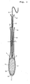
- Fig. 1 is a longitudinal section showing the state in which a tampon is fitted in an applicator according to the invention
- Figs. 2A and 2B are enlarged sections showing the rear end and the front end of an inner cylinder of the applicator
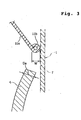
- Fig. 3 is an enlarged section showing the shape of the edge portion of the push portion at the front end of the inner cylinder
- Figs. 4A, 4B, 4C and 4D are explanatory diagrams showing one embodiment of a method for manufacturing the applicator.
- the tampon applicator as shown in Fig. 1, is constructed to include an outer cylinder 1 and an inner cylinder 2.
- a tampon 3 which is formed by compress-molding absorptive fibers such as cottons
- a take-out cord 4 which is extended rearwardly from the inside of the outer cylinder 1 through the inner cylinder 2.
- the outer cylinder 1 is injection-molded of a thermoplastic resin such as the PE (polyethylene) or the PP (polypropylene).
- the outer cylinder 1 thus injection-molded is smooth on its surface but is not sharp at the edge portions of valves 6 around an end protruding mouth 5 provided at the leading portion of the outer cylinder 1, thereby to give little uncomfortable feeling when it comes into contact with the human body.
- the thermoplastic resin is preferably exemplified by the LDPE (i.e., low density polyethylene) when the outer cylinder 1 is injection-molded, so that the resin may flow without stagnation in the mold thereby to provide a smooth surface and a thickness as small as possible.
- the thickness of the outer cylinder 1 to be formed by the injection-molding is within a range of 0.6 mm to 1.0 mm.
- a large diameter portion 7 for fitting the tampon 3 therein, and this large diameter portion 7 forms a curved face portion 7a at its leading portion.
- the large diameter portion 7 is provided at its leading end with the protruding mouth 5 through which the tampon 3 is pushed out, and the curved face portion 7a is provided with a plurality of the deformable valves 6 in a petal shape.
- the valves 6 are opened at the leading end of the large diameter portion 7. After the tampon 3 is fitted in the large-diameter portion 7, the valves 6 is thermally deformed into the curved face portion 7a.
- the outer cylinder 1 is provided with a small diameter portion 8 on the side of the root end with respect to the center of the outer cylinder 1, and a root end 9 is diametrically enlarged to form an opening 10.
- the inner cylinder 2 is formed of an extruded material by extrusion-molding a thermoplastic resin such as PE, PP or PET (i.e., polyethylene terephthalate) into a cylindrical shape (e.g., a straw shape or a pipe shape). More preferably, the extruded thermoplastic resin is oriented in the axial direction.
- the extruded material thus extrusion-molded and axially oriented is improved in the axial orientation so that its axial buckling strength is enhanced. Even if the thickness is made so small as 0.4 mm orless (up to about 0.1 mm) whereas the internal diameter is made so small as 7 mm or less (up to about 3 mm), the inner cylinder 2 retains a sufficient buckling strength. Accordingly, the inner cylinder 2 is hardly buckled or not folded, when the inner cylinder 2 is pushed to push out the tampon 3 from the protruding mouth 5 of the outer cylinder 1 upon use.
- the inner cylinder 2 is movably inserted into the small diameter portion 8 of the outer cylinder 1 and has a push portion 11 at its front end.
- This push portion 11 is diverged to easily push the tampon 3 from its rear end and to prevent the inner cylinder 2 from being withdrawn from a root end 9 of the outer cylinder 1. Therefore, the external diameter D1 (see Fig. 2B) of the push portion 11 is made larger than the internal diameter d of the small diameter portion 8 of the outer cylinder 1.
- the inner cylinder 2 At the rear end of the inner cylinder 2, there is formed a diverging portion 12.
- the diverging portion 12 By forming the diverging portion 12, the inner cylinder 2 can be easily pushed, even though slender, at its rear end with a finger of the user.
- the external diameter D2 of the diverging portion 12 is made larger than the internal diameter of the root end of the outer cylinder 1 to prevent the diverging portion 12 from entering into the outer cylinder 1 from the opening 10.
- the push portion 11 to be formed at the front end of the inner cylinder 2 is preferably formed into such a shape that the external diameter becomes gradually larger toward the front end, as shown in Figs. 1 and 2B.
- the sectional shape of a diverging wall 11a of the push portion 11 is linearly changed so that the external diameter becomes gradually larger, as shown in Fig. 2B, whereby the push portion 11 may be counter-tapered.
- it may be formed into a bugle shape so that the external diameter of the sectional shape of the diverging wall lla becomes gradually larger in a curved face shape toward the front end.
- a bent portion 11b is formed at an edge portion of the front end of the diverging wall 11a.
- the bent portion 11b is formed by outwardly rounding the edge portion of the diverging wall 11a.
- this bent portion 11b may be formed by outwardly folding the edge portion into two.
- the bent portion 11b may be rounded inwardly of the diverging wall lla or folded into two inwardly thereof.
- the push portion 11 is formed with the bent portion 11b, the contact with an edge is not felt by the body to give no uncomfortable feeling to the body, even if the push portion 11 comes into contact with the vaginal cavity when the tampon 3 is pushed out thereinto.
- the width W of the bent portion 11b is smaller than the diameter Da of the take-out cord 4.
- the width W of the bent portion 11b By the width W of the bent portion 11b, a clearance is established between the bent portion 11b and the inner wall of the outer cylinder 1. Accordingly, in case where the width W is excessively large, the leading end of the take-out cord 4-tends to be caught in the clearance between the bent portion 11b and the inner wall of the outer cylinder 1, when it is inserted into the inner cylinder 2. As a result, it becomes difficult to put the take-out cord 4 through the inner cylinder 2.
- the push portion 11 can be easily formed by pushing a heated press die 15 as shown in Fig. 2B, onto the front portion of the inner cylinder 2.
- a heated press die 15 as shown in Fig. 2B
- the press die 15 there are formed a tapered portion 15a which is located at the central portion, and a groove 15b which is extended circumferentially in the bottom portion of the tapered portion 15a.
- the diverging wall 11a can be formed by the tapered portion 15a, and the edge portion of the diverging wall lla can be bent by the groove 15b.
- the diverging portion 12 at the rear end of the inner cylinder 2 is also preferably formed into the counter-tapered shape or the bugle shape. Furthermore, an edge portion of the rear end of the diverging portion 12 is rounded or folded into two outwardly or inwardly of a diverging portion 12a to form a bent portion 12b. By forming this bent portion 12b, the finger of the user is to contact the bent portion 12b, when the diverging portion 12 is pushed by the finger, so that the resistance to the finger can be reduced.
- This diverging portion 12 can also be easily formed by pushing a press die, which has the same shape as but a slightly smaller size than the press die 15 shown in Fig. 2B, onto the rear end of the inner cylinder 2.
- the push portion 11 and the diverging portion 12 should not necessarily be limited in the counter-tapered shape or the bugle shape.
- the push portion 11 and the diverging portion 12 may be formed by expanding the body portion of the inner cylinder 2, while keeping their external shapes, generally into the cylindrical shape.
- Figs. 4A to 4D show respectively a step of one example of the method for manufacturing the tampon applicator.
- thermoplastic resin is melted and extruded by a melt extruder 21, shaped by a die 22 into a cylindrical (e.g., straw or pipe) shape, axially oriented by an orienting delivery unit 23, and cooled to form an extruded material 2a.
- a melt extruder 21 shaped by a die 22 into a cylindrical (e.g., straw or pipe) shape, axially oriented by an orienting delivery unit 23, and cooled to form an extruded material 2a.
- the extruded material 2a is cut by a cutter 24 to obtain a predetermined length of the inner cylinder 2.
- the press die 15 is heated and pushed onto the front end of the inner cylinder 2 to form the counter-tapered (or bugle shaped) push portion 11.
- the outer cylinder 1 is injection-molded into the shape shown in Fig. 4D.
- the rear end of the inner cylinder 2 before being formed with the push portion 11, is inserted from the protruding mouth 5 at the leading end of the outer cylinder 1, and is put through the small diameter portion 8 so that it is projected rearwardly from the opening 10 at the root end 9.
- the press die is heated and pushed onto the rear end of the inner cylinder 2 to form the diverging portion 12.
- the tampon 3 is inserted from the protruding mouth 5 into the large diameter portion 7 of the outer cylinder 1.
- the take-out cord 4 is pulled out rearwardly through the inner cylinder 2.
- the valves 6 around the protruding mouth 5 of the outer cylinder 1 are thermally deformed so that the protruding mouth 5 is plugged with the curvedly deformed valves 6, as shown in Fig. 1.
- the inner cylinder of the applicator is formed of the extruded material so that it can be manufactured at a lower cost than that of the injection-molded one. It is also possible to lower the cost for changing the diameter or shape of the inner cylinder. Furthermore, the inner cylinder thus formed of the extruded material can freely select its thickness or diameter so that it can be made thin or diametrically small to reduce the amount of resin to be employed. In this case, the buckling strength in the axial direction thereof can be enhanced if the extruded material to be employed is axially oriented. Furthermore, the push portion at the front end and the diverging portion at the rear end of the inner cylinder can be easily shaped.
Landscapes
- Health & Medical Sciences (AREA)
- Epidemiology (AREA)
- Engineering & Computer Science (AREA)
- Biomedical Technology (AREA)
- Heart & Thoracic Surgery (AREA)
- Vascular Medicine (AREA)
- Life Sciences & Earth Sciences (AREA)
- Animal Behavior & Ethology (AREA)
- General Health & Medical Sciences (AREA)
- Public Health (AREA)
- Veterinary Medicine (AREA)
- Absorbent Articles And Supports Therefor (AREA)
Abstract
Description
wherein the inner cylinder is formed of an extruded material which is extrusion-molded of a thermoplastic resin into a cylindrical shape, and is provided at the front end thereof with a push portion which is deformed to have a larger diameter from the extruded material.
wherein the push portion of the inner cylinder is positioned in the large diameter portion and has a larger external diameter than an internal diameter of the small diameter portion.
Claims (8)
- An applicator for a tampon comprising: an outer cylinder including a protruding mouth at a leading end thereof, through which a tampon is pushed out and an opening at a root end thereof; and an inner cylinder for pushing out said tampon which has a front end located in said outer cylinder and a rear end protruding rearwardly from said outer cylinder through said opening,
wherein said inner cylinder is formed of an extruded material which is extrusion-molded of a thermoplastic resin into a cylindrical shape, and is provided at the front end thereof with a push portion which is deformed to have a larger diameter from said extruded material. - An applicator for a tampon as set forth in claim 1,wherein said outer cylinder includes a large diameter portion for fitting said tampon therein, and a small diameter portion extending from said large diameter portion toward the root end, andwherein said push portion of said inner cylinder is positioned in said large diameter portion and has a larger external diameter than an internal diameter of said small diameter portion.
- An applicator for a tampon as set forth in claim 1,
wherein said extruded material is extrusion-molded and then axially oriented. - An applicator for a tampon as set forth in claim 1,
wherein said push portion has an external diameter which is gradually diverged toward the front end thereof. - An applicator for a tampon as set forth in claim 1,
wherein said inner cylinder is provided at the rear end thereof with a diverging portion which is deformed to have a diameter gradually enlarged toward the rear end. - An applicator for a tampon as set forth in claim 5,
wherein said diverging portion formed at the rear end of said inner cylinder have an edge portion which is bent outwardly or inwardly of said diverging portion. - An applicator for a tampon as set forth in claim 2,
wherein said push portion formed at the front end of said inner cylinder have an edge portion which is bent outwardly or inwardly of said push portion. - An applicator for a tampon as set forth in claim 7,
wherein a bent portion which is bent outwardly or inwardly of said push portion has a width size smaller than a thickness of a take-out cord extending from said tampon.
Applications Claiming Priority (2)
| Application Number | Priority Date | Filing Date | Title |
|---|---|---|---|
| JP32927599A JP3725383B2 (en) | 1999-11-19 | 1999-11-19 | Tampon applicator |
| JP32927599 | 1999-11-19 |
Publications (3)
| Publication Number | Publication Date |
|---|---|
| EP1101472A2 true EP1101472A2 (en) | 2001-05-23 |
| EP1101472A3 EP1101472A3 (en) | 2001-07-18 |
| EP1101472B1 EP1101472B1 (en) | 2005-02-16 |
Family
ID=18219639
Family Applications (1)
| Application Number | Title | Priority Date | Filing Date |
|---|---|---|---|
| EP00310300A Expired - Lifetime EP1101472B1 (en) | 1999-11-19 | 2000-11-20 | Applicator for tampons |
Country Status (13)
| Country | Link |
|---|---|
| US (1) | US6432076B1 (en) |
| EP (1) | EP1101472B1 (en) |
| JP (1) | JP3725383B2 (en) |
| KR (1) | KR100710652B1 (en) |
| CN (2) | CN101259062B (en) |
| AU (1) | AU775785B2 (en) |
| BR (1) | BR0005449B1 (en) |
| CA (1) | CA2325269C (en) |
| DE (1) | DE60018142T2 (en) |
| ID (1) | ID28436A (en) |
| MY (1) | MY122601A (en) |
| SG (1) | SG103270A1 (en) |
| TW (1) | TW530638U (en) |
Cited By (8)
| Publication number | Priority date | Publication date | Assignee | Title |
|---|---|---|---|---|
| WO2004024193A2 (en) | 2002-09-12 | 2004-03-25 | Playtex Products, Inc. | Ergonomic tampon applicator |
| WO2005018520A1 (en) * | 2003-08-12 | 2005-03-03 | The Procter & Gamble Company | A process for making an applicator with a locking mechanism comprising a plurality of slits |
| USD515212S1 (en) | 2003-04-04 | 2006-02-14 | Playtex Products, Inc. | Tampon applicator barrel with finger grips |
| EP1653900A1 (en) * | 2003-08-12 | 2006-05-10 | The Procter & Gamble Company | Applicator with a locking mechanism comprising a plurality of slits |
| US7044928B2 (en) | 2003-04-04 | 2006-05-16 | Platex Products, Inc. | Tampon applicator assembly having an improved plunger and methods of making |
| USD572362S1 (en) | 2003-04-04 | 2008-07-01 | Playtex Products, Inc. | Tampon applicator with finger grip |
| EP2077100A1 (en) * | 1999-11-19 | 2009-07-08 | Uni-charm Corporation | Applicator for tampons |
| WO2010090929A3 (en) * | 2009-02-05 | 2011-06-23 | Playtex Products, Llc | Microcellular injection molding processes for personal and consumer care products and packaging |
Families Citing this family (22)
| Publication number | Priority date | Publication date | Assignee | Title |
|---|---|---|---|---|
| WO2004000160A2 (en) | 2002-06-21 | 2003-12-31 | Playtex Products, Inc. | Tapered tampon applicator |
| US7704242B2 (en) * | 2003-04-04 | 2010-04-27 | Playtex Products, Inc. | Barrel for a tampon applicator assembly and methods of forming |
| US8372027B2 (en) * | 2003-04-04 | 2013-02-12 | Playtex Products, Inc. | Tampon applicator assembly |
| JP4643565B2 (en) * | 2003-04-04 | 2011-03-02 | プレイテックス プロダクツ エルエルシー | Outer cylinder and formation method for tampon applicator assembly |
| US9192522B2 (en) | 2003-05-02 | 2015-11-24 | Eveready Battery Company, Inc. | Tampon assembly having shaped pledget |
| AU2004253945B2 (en) * | 2003-06-26 | 2009-02-19 | Playtex Products, Inc. | A coating composition and articles coated therewith |
| US7563401B2 (en) * | 2003-06-27 | 2009-07-21 | Playtex Products, Inc. | Tampon pledget having a shaped tip and method of making same |
| US7081110B2 (en) * | 2003-07-17 | 2006-07-25 | The Procter & Gamble Company | Applicator having an indented fingergrip with raised portions |
| USD511382S1 (en) * | 2004-02-20 | 2005-11-08 | Wet Trust Japan Co., Ltd. | Injection apparatus |
| AU2005220860B2 (en) | 2004-03-08 | 2011-03-03 | Playtex Products, Inc. | Tampon applicator and method for making same |
| US8372028B2 (en) * | 2004-11-19 | 2013-02-12 | The Procter & Gamble Company | Tampon applicator |
| US8308675B2 (en) * | 2006-03-31 | 2012-11-13 | Mcneil-Ppc, Inc. | Applicator device |
| US7815594B2 (en) | 2006-06-12 | 2010-10-19 | Playtex Products, Inc. | Tampon assembly providing proper bodily placement of a pledget |
| US20080167599A1 (en) * | 2007-01-10 | 2008-07-10 | The Procter & Gamble Comapny | Active applicator |
| US20080167598A1 (en) * | 2007-01-10 | 2008-07-10 | The Procter & Gamble Company | Active applicator |
| US20090192436A1 (en) * | 2008-01-24 | 2009-07-30 | Nancy Karapasha | Applicator having plunger with gripping elements |
| US8449491B2 (en) * | 2009-06-22 | 2013-05-28 | The Procter & Gamble Company | Applicator having extended gripping formations |
| US9233029B2 (en) * | 2009-06-22 | 2016-01-12 | The Procter & Gamble Company | Nesting tampon applicator |
| EP2821042A1 (en) * | 2013-07-02 | 2015-01-07 | Ruggli Projects AG | Tampon applicator and assembly method |
| US11529264B2 (en) | 2017-10-06 | 2022-12-20 | Essity Hygiene And Health Aktiebolag | Tampon applicator |
| CH714846A9 (en) * | 2018-03-29 | 2020-01-15 | Ruggli Projects Ag | Device for shaping tampons. |
| CN112402107A (en) * | 2019-08-21 | 2021-02-26 | 吴静茹 | Conduit type tampon, telescopic conduit group thereof and tampon finger sleeve |
Family Cites Families (6)
| Publication number | Priority date | Publication date | Assignee | Title |
|---|---|---|---|---|
| GB549053A (en) | 1940-06-28 | 1942-11-04 | Johnson & Johnson | Improved tampon applicator |
| US3148680A (en) | 1961-10-09 | 1964-09-15 | Johnson & Johnson | Tampon applicator |
| US3628533A (en) * | 1970-04-20 | 1971-12-21 | Johnson & Johnson | Domed-tipped applicator for catamenial tampons |
| JPS6294156A (en) * | 1985-10-18 | 1987-04-30 | ユニ・チヤ−ム株式会社 | Sanitary tampon insert jig |
| US5267953A (en) | 1986-04-23 | 1993-12-07 | Kimberly-Clark Corporation | Curved tampon applicator and a process for forming the applicator and for assembling an absorbent tampon into said applicator |
| US5437628A (en) * | 1993-11-10 | 1995-08-01 | Kimberly-Clark Corporation | Curved tampon applicator having an improved fingergrip |
-
1999
- 1999-11-19 JP JP32927599A patent/JP3725383B2/en not_active Expired - Fee Related
-
2000
- 2000-11-09 CA CA002325269A patent/CA2325269C/en not_active Expired - Lifetime
- 2000-11-09 US US09/710,576 patent/US6432076B1/en not_active Expired - Lifetime
- 2000-11-10 MY MYPI20005300A patent/MY122601A/en unknown
- 2000-11-15 SG SG200006622A patent/SG103270A1/en unknown
- 2000-11-17 AU AU71682/00A patent/AU775785B2/en not_active Ceased
- 2000-11-17 BR BRPI0005449-6A patent/BR0005449B1/en not_active IP Right Cessation
- 2000-11-17 CN CN2008100862347A patent/CN101259062B/en not_active Expired - Lifetime
- 2000-11-17 ID IDP20000993D patent/ID28436A/en unknown
- 2000-11-17 TW TW089219984U patent/TW530638U/en not_active IP Right Cessation
- 2000-11-17 CN CN00137334A patent/CN1299640A/en active Pending
- 2000-11-17 KR KR1020000068375A patent/KR100710652B1/en not_active Expired - Lifetime
- 2000-11-20 EP EP00310300A patent/EP1101472B1/en not_active Expired - Lifetime
- 2000-11-20 DE DE60018142T patent/DE60018142T2/en not_active Expired - Lifetime
Cited By (11)
| Publication number | Priority date | Publication date | Assignee | Title |
|---|---|---|---|---|
| EP2077100A1 (en) * | 1999-11-19 | 2009-07-08 | Uni-charm Corporation | Applicator for tampons |
| WO2004024193A2 (en) | 2002-09-12 | 2004-03-25 | Playtex Products, Inc. | Ergonomic tampon applicator |
| EP1545418A4 (en) * | 2002-09-12 | 2010-09-08 | Playtex Products Inc | Ergonomic tampon applicator |
| US8337478B2 (en) | 2002-09-12 | 2012-12-25 | Playtex Products, Inc. | Ergonomic tampon applicator |
| US9421135B2 (en) | 2002-09-12 | 2016-08-23 | Edgewell Personal Care Brands, Llc. | Ergonomic tampon applicator |
| USD515212S1 (en) | 2003-04-04 | 2006-02-14 | Playtex Products, Inc. | Tampon applicator barrel with finger grips |
| US7044928B2 (en) | 2003-04-04 | 2006-05-16 | Platex Products, Inc. | Tampon applicator assembly having an improved plunger and methods of making |
| USD572362S1 (en) | 2003-04-04 | 2008-07-01 | Playtex Products, Inc. | Tampon applicator with finger grip |
| WO2005018520A1 (en) * | 2003-08-12 | 2005-03-03 | The Procter & Gamble Company | A process for making an applicator with a locking mechanism comprising a plurality of slits |
| EP1653900A1 (en) * | 2003-08-12 | 2006-05-10 | The Procter & Gamble Company | Applicator with a locking mechanism comprising a plurality of slits |
| WO2010090929A3 (en) * | 2009-02-05 | 2011-06-23 | Playtex Products, Llc | Microcellular injection molding processes for personal and consumer care products and packaging |
Also Published As
| Publication number | Publication date |
|---|---|
| BR0005449A (en) | 2001-07-03 |
| DE60018142T2 (en) | 2006-02-09 |
| DE60018142D1 (en) | 2005-03-24 |
| CN101259062B (en) | 2011-01-12 |
| MY122601A (en) | 2006-04-29 |
| CN1299640A (en) | 2001-06-20 |
| SG103270A1 (en) | 2004-04-29 |
| AU7168200A (en) | 2001-05-24 |
| CN101259062A (en) | 2008-09-10 |
| KR20010051766A (en) | 2001-06-25 |
| US6432076B1 (en) | 2002-08-13 |
| TW530638U (en) | 2003-05-01 |
| BR0005449B1 (en) | 2008-11-18 |
| JP2001145657A (en) | 2001-05-29 |
| ID28436A (en) | 2001-05-24 |
| JP3725383B2 (en) | 2005-12-07 |
| CA2325269A1 (en) | 2001-05-19 |
| AU775785B2 (en) | 2004-08-12 |
| KR100710652B1 (en) | 2007-04-24 |
| EP1101472A3 (en) | 2001-07-18 |
| EP1101472B1 (en) | 2005-02-16 |
| CA2325269C (en) | 2006-11-14 |
Similar Documents
| Publication | Publication Date | Title |
|---|---|---|
| EP1101472B1 (en) | Applicator for tampons | |
| CA2325669C (en) | Applicator for tampons | |
| US8458882B2 (en) | Method for assembling a tampon applicator | |
| US9339419B2 (en) | Tampon applicator | |
| US8556845B2 (en) | Multiple-component tampon applicator | |
| US3830236A (en) | Applicator tube for inserting hygienic media | |
| MXPA03008949A (en) | Applicator having improved gripper end. | |
| US20240065897A1 (en) | Composition For Thin Walled Molded Parts | |
| CN1813647B (en) | Applicator for feminine hygiene tampon and feminine hygiene product | |
| CA1160530A (en) | Extruded plastic hygienic applicator and method of manufacturing same | |
| CA2217282A1 (en) | A thin walled tube having an internal rib | |
| JPH0433262B2 (en) | ||
| TH46999A (en) | Insert sanitary cloth insert | |
| TH49167B (en) | Insert sanitary cloth insert |
Legal Events
| Date | Code | Title | Description |
|---|---|---|---|
| PUAI | Public reference made under article 153(3) epc to a published international application that has entered the european phase |
Free format text: ORIGINAL CODE: 0009012 |
|
| AK | Designated contracting states |
Kind code of ref document: A2 Designated state(s): DE FR GB NL SE |
|
| AX | Request for extension of the european patent |
Free format text: AL;LT;LV;MK;RO;SI |
|
| PUAL | Search report despatched |
Free format text: ORIGINAL CODE: 0009013 |
|
| AK | Designated contracting states |
Kind code of ref document: A3 Designated state(s): AT BE CH CY DE DK ES FI FR GB GR IE IT LI LU MC NL PT SE TR |
|
| AX | Request for extension of the european patent |
Free format text: AL;LT;LV;MK;RO;SI |
|
| 17P | Request for examination filed |
Effective date: 20020105 |
|
| AKX | Designation fees paid |
Free format text: DE FR GB NL SE |
|
| 17Q | First examination report despatched |
Effective date: 20031222 |
|
| RAP1 | Party data changed (applicant data changed or rights of an application transferred) |
Owner name: UNI-CHARM CORPORATION |
|
| GRAP | Despatch of communication of intention to grant a patent |
Free format text: ORIGINAL CODE: EPIDOSNIGR1 |
|
| GRAS | Grant fee paid |
Free format text: ORIGINAL CODE: EPIDOSNIGR3 |
|
| GRAA | (expected) grant |
Free format text: ORIGINAL CODE: 0009210 |
|
| AK | Designated contracting states |
Kind code of ref document: B1 Designated state(s): DE FR GB NL SE |
|
| REG | Reference to a national code |
Ref country code: GB Ref legal event code: FG4D |
|
| REF | Corresponds to: |
Ref document number: 60018142 Country of ref document: DE Date of ref document: 20050324 Kind code of ref document: P |
|
| REG | Reference to a national code |
Ref country code: SE Ref legal event code: TRGR |
|
| PLBE | No opposition filed within time limit |
Free format text: ORIGINAL CODE: 0009261 |
|
| STAA | Information on the status of an ep patent application or granted ep patent |
Free format text: STATUS: NO OPPOSITION FILED WITHIN TIME LIMIT |
|
| ET | Fr: translation filed | ||
| 26N | No opposition filed |
Effective date: 20051117 |
|
| REG | Reference to a national code |
Ref country code: FR Ref legal event code: PLFP Year of fee payment: 16 |
|
| REG | Reference to a national code |
Ref country code: FR Ref legal event code: PLFP Year of fee payment: 17 |
|
| REG | Reference to a national code |
Ref country code: FR Ref legal event code: PLFP Year of fee payment: 18 |
|
| REG | Reference to a national code |
Ref country code: FR Ref legal event code: PLFP Year of fee payment: 19 |
|
| PGFP | Annual fee paid to national office [announced via postgrant information from national office to epo] |
Ref country code: NL Payment date: 20181017 Year of fee payment: 19 |
|
| PGFP | Annual fee paid to national office [announced via postgrant information from national office to epo] |
Ref country code: AT Payment date: 20181025 Year of fee payment: 19 |
|
| PGFP | Annual fee paid to national office [announced via postgrant information from national office to epo] |
Ref country code: DE Payment date: 20191105 Year of fee payment: 20 |
|
| PGFP | Annual fee paid to national office [announced via postgrant information from national office to epo] |
Ref country code: FR Payment date: 20191015 Year of fee payment: 20 |
|
| PGFP | Annual fee paid to national office [announced via postgrant information from national office to epo] |
Ref country code: GB Payment date: 20191122 Year of fee payment: 20 |
|
| REG | Reference to a national code |
Ref country code: SE Ref legal event code: EUG |
|
| REG | Reference to a national code |
Ref country code: NL Ref legal event code: MM Effective date: 20191201 |
|
| PG25 | Lapsed in a contracting state [announced via postgrant information from national office to epo] |
Ref country code: SE Free format text: LAPSE BECAUSE OF NON-PAYMENT OF DUE FEES Effective date: 20191121 |
|
| PG25 | Lapsed in a contracting state [announced via postgrant information from national office to epo] |
Ref country code: NL Free format text: LAPSE BECAUSE OF NON-PAYMENT OF DUE FEES Effective date: 20191201 |
|
| REG | Reference to a national code |
Ref country code: DE Ref legal event code: R071 Ref document number: 60018142 Country of ref document: DE |
|
| REG | Reference to a national code |
Ref country code: GB Ref legal event code: PE20 Expiry date: 20201119 |
|
| PG25 | Lapsed in a contracting state [announced via postgrant information from national office to epo] |
Ref country code: GB Free format text: LAPSE BECAUSE OF EXPIRATION OF PROTECTION Effective date: 20201119 |