EP1100174A2 - Power supply system and control method for the system - Google Patents
Power supply system and control method for the system Download PDFInfo
- Publication number
- EP1100174A2 EP1100174A2 EP00124527A EP00124527A EP1100174A2 EP 1100174 A2 EP1100174 A2 EP 1100174A2 EP 00124527 A EP00124527 A EP 00124527A EP 00124527 A EP00124527 A EP 00124527A EP 1100174 A2 EP1100174 A2 EP 1100174A2
- Authority
- EP
- European Patent Office
- Prior art keywords
- voltage
- battery
- load
- bulb
- rated voltage
- Prior art date
- Legal status (The legal status is an assumption and is not a legal conclusion. Google has not performed a legal analysis and makes no representation as to the accuracy of the status listed.)
- Granted
Links
Images



Classifications
-
- H—ELECTRICITY
- H02—GENERATION; CONVERSION OR DISTRIBUTION OF ELECTRIC POWER
- H02J—ELECTRIC POWER NETWORKS; CIRCUIT ARRANGEMENTS OR SYSTEMS FOR SUPPLYING OR DISTRIBUTING ELECTRIC POWER; SYSTEMS FOR STORING ELECTRIC ENERGY
- H02J7/00—Circuit arrangements for charging or discharging batteries or for supplying loads from batteries
- H02J7/14—Circuit arrangements for charging or discharging batteries or for supplying loads from batteries for charging batteries from dynamo-electric generators driven at varying speed, e.g. on vehicle
- H02J7/1438—Circuit arrangements for charging or discharging batteries or for supplying loads from batteries for charging batteries from dynamo-electric generators driven at varying speed, e.g. on vehicle in combination with power supplies for loads other than batteries
-
- B—PERFORMING OPERATIONS; TRANSPORTING
- B60—VEHICLES IN GENERAL
- B60L—PROPULSION OF ELECTRICALLY-PROPELLED VEHICLES; SUPPLYING ELECTRIC POWER FOR AUXILIARY EQUIPMENT OF ELECTRICALLY-PROPELLED VEHICLES; ELECTRODYNAMIC BRAKE SYSTEMS FOR VEHICLES IN GENERAL; MAGNETIC SUSPENSION OR LEVITATION FOR VEHICLES; MONITORING OPERATING VARIABLES OF ELECTRICALLY-PROPELLED VEHICLES; ELECTRIC SAFETY DEVICES FOR ELECTRICALLY-PROPELLED VEHICLES
- B60L1/00—Supplying electric power to auxiliary equipment of vehicles
- B60L1/003—Supplying electric power to auxiliary equipment of vehicles to auxiliary motors, e.g. for pumps, compressors
-
- B—PERFORMING OPERATIONS; TRANSPORTING
- B60—VEHICLES IN GENERAL
- B60L—PROPULSION OF ELECTRICALLY-PROPELLED VEHICLES; SUPPLYING ELECTRIC POWER FOR AUXILIARY EQUIPMENT OF ELECTRICALLY-PROPELLED VEHICLES; ELECTRODYNAMIC BRAKE SYSTEMS FOR VEHICLES IN GENERAL; MAGNETIC SUSPENSION OR LEVITATION FOR VEHICLES; MONITORING OPERATING VARIABLES OF ELECTRICALLY-PROPELLED VEHICLES; ELECTRIC SAFETY DEVICES FOR ELECTRICALLY-PROPELLED VEHICLES
- B60L50/00—Electric propulsion with power supplied within the vehicle
- B60L50/10—Electric propulsion with power supplied within the vehicle using propulsion power supplied by engine-driven generators, e.g. generators driven by combustion engines
- B60L50/15—Electric propulsion with power supplied within the vehicle using propulsion power supplied by engine-driven generators, e.g. generators driven by combustion engines with additional electric power supply
-
- B—PERFORMING OPERATIONS; TRANSPORTING
- B60—VEHICLES IN GENERAL
- B60L—PROPULSION OF ELECTRICALLY-PROPELLED VEHICLES; SUPPLYING ELECTRIC POWER FOR AUXILIARY EQUIPMENT OF ELECTRICALLY-PROPELLED VEHICLES; ELECTRODYNAMIC BRAKE SYSTEMS FOR VEHICLES IN GENERAL; MAGNETIC SUSPENSION OR LEVITATION FOR VEHICLES; MONITORING OPERATING VARIABLES OF ELECTRICALLY-PROPELLED VEHICLES; ELECTRIC SAFETY DEVICES FOR ELECTRICALLY-PROPELLED VEHICLES
- B60L58/00—Methods or circuit arrangements for monitoring or controlling batteries or fuel cells, specially adapted for electric vehicles
- B60L58/10—Methods or circuit arrangements for monitoring or controlling batteries or fuel cells, specially adapted for electric vehicles for monitoring or controlling batteries
- B60L58/18—Methods or circuit arrangements for monitoring or controlling batteries or fuel cells, specially adapted for electric vehicles for monitoring or controlling batteries of two or more battery modules
- B60L58/20—Methods or circuit arrangements for monitoring or controlling batteries or fuel cells, specially adapted for electric vehicles for monitoring or controlling batteries of two or more battery modules having different nominal voltages
-
- H—ELECTRICITY
- H02—GENERATION; CONVERSION OR DISTRIBUTION OF ELECTRIC POWER
- H02J—ELECTRIC POWER NETWORKS; CIRCUIT ARRANGEMENTS OR SYSTEMS FOR SUPPLYING OR DISTRIBUTING ELECTRIC POWER; SYSTEMS FOR STORING ELECTRIC ENERGY
- H02J7/00—Circuit arrangements for charging or discharging batteries or for supplying loads from batteries
- H02J7/34—Parallel operation in networks using both storage and other DC sources, e.g. providing buffering
- H02J7/342—The other DC source being a battery actively interacting with the first one, i.e. battery to battery charging
-
- H—ELECTRICITY
- H02—GENERATION; CONVERSION OR DISTRIBUTION OF ELECTRIC POWER
- H02J—ELECTRIC POWER NETWORKS; CIRCUIT ARRANGEMENTS OR SYSTEMS FOR SUPPLYING OR DISTRIBUTING ELECTRIC POWER; SYSTEMS FOR STORING ELECTRIC ENERGY
- H02J7/00—Circuit arrangements for charging or discharging batteries or for supplying loads from batteries
- H02J7/865—Battery or charger load switching, e.g. concurrent charging and load supply
-
- B—PERFORMING OPERATIONS; TRANSPORTING
- B60—VEHICLES IN GENERAL
- B60L—PROPULSION OF ELECTRICALLY-PROPELLED VEHICLES; SUPPLYING ELECTRIC POWER FOR AUXILIARY EQUIPMENT OF ELECTRICALLY-PROPELLED VEHICLES; ELECTRODYNAMIC BRAKE SYSTEMS FOR VEHICLES IN GENERAL; MAGNETIC SUSPENSION OR LEVITATION FOR VEHICLES; MONITORING OPERATING VARIABLES OF ELECTRICALLY-PROPELLED VEHICLES; ELECTRIC SAFETY DEVICES FOR ELECTRICALLY-PROPELLED VEHICLES
- B60L2240/00—Control parameters of input or output; Target parameters
- B60L2240/40—Drive Train control parameters
- B60L2240/54—Drive Train control parameters related to batteries
- B60L2240/545—Temperature
-
- B—PERFORMING OPERATIONS; TRANSPORTING
- B60—VEHICLES IN GENERAL
- B60L—PROPULSION OF ELECTRICALLY-PROPELLED VEHICLES; SUPPLYING ELECTRIC POWER FOR AUXILIARY EQUIPMENT OF ELECTRICALLY-PROPELLED VEHICLES; ELECTRODYNAMIC BRAKE SYSTEMS FOR VEHICLES IN GENERAL; MAGNETIC SUSPENSION OR LEVITATION FOR VEHICLES; MONITORING OPERATING VARIABLES OF ELECTRICALLY-PROPELLED VEHICLES; ELECTRIC SAFETY DEVICES FOR ELECTRICALLY-PROPELLED VEHICLES
- B60L2240/00—Control parameters of input or output; Target parameters
- B60L2240/40—Drive Train control parameters
- B60L2240/54—Drive Train control parameters related to batteries
- B60L2240/547—Voltage
-
- Y—GENERAL TAGGING OF NEW TECHNOLOGICAL DEVELOPMENTS; GENERAL TAGGING OF CROSS-SECTIONAL TECHNOLOGIES SPANNING OVER SEVERAL SECTIONS OF THE IPC; TECHNICAL SUBJECTS COVERED BY FORMER USPC CROSS-REFERENCE ART COLLECTIONS [XRACs] AND DIGESTS
- Y02—TECHNOLOGIES OR APPLICATIONS FOR MITIGATION OR ADAPTATION AGAINST CLIMATE CHANGE
- Y02T—CLIMATE CHANGE MITIGATION TECHNOLOGIES RELATED TO TRANSPORTATION
- Y02T10/00—Road transport of goods or passengers
- Y02T10/60—Other road transportation technologies with climate change mitigation effect
- Y02T10/70—Energy storage systems for electromobility, e.g. batteries
-
- Y—GENERAL TAGGING OF NEW TECHNOLOGICAL DEVELOPMENTS; GENERAL TAGGING OF CROSS-SECTIONAL TECHNOLOGIES SPANNING OVER SEVERAL SECTIONS OF THE IPC; TECHNICAL SUBJECTS COVERED BY FORMER USPC CROSS-REFERENCE ART COLLECTIONS [XRACs] AND DIGESTS
- Y02—TECHNOLOGIES OR APPLICATIONS FOR MITIGATION OR ADAPTATION AGAINST CLIMATE CHANGE
- Y02T—CLIMATE CHANGE MITIGATION TECHNOLOGIES RELATED TO TRANSPORTATION
- Y02T10/00—Road transport of goods or passengers
- Y02T10/60—Other road transportation technologies with climate change mitigation effect
- Y02T10/7072—Electromobility specific charging systems or methods for batteries, ultracapacitors, supercapacitors or double-layer capacitors
Definitions
- the invention relates to a power supply system and control method for the system, more particularly, relates to the charging circuit for a battery connected to a load that changes in characteristics, such as the length of service life, brightness, etc., if a voltage exceeding a rated voltage is applied thereto, and control method for the charging circuit.
- a battery for a vehicle be installed in a trunk room instead of an engine room. Installation of a battery in a trunk room makes it possible to dispose the battery apart from the engine.
- the trunk is apt to be affected by external temperature. That is, if the external temperature decreases, the battery temperature also decreases. Therefore, a measure for temperature changes is needed. In general, it is effective to change the charging voltage of a battery in accordance with the temperature of the battery.
- Japanese Patent Application Laid-Open No. HEI 4-351436 describes an art for changing the charging voltage of a battery in accordance with the temperature of the battery. More specifically, as the battery temperature becomes lower, a higher charging voltage is set to charge the battery.
- a load for example, a bulb or the like, which changes in characteristics, such as the length of service life, brightness, etc. if receiving an applied voltage higher than its rated voltage. That is, if the battery temperature is low, a high charging voltage is needed, so that a charging voltage exceeding the rated voltage of the load is applied to the load in some cases. As a result, the characteristics of the load connected to the battery deteriorate although the battery is efficiently charged.
- a power supply system includes a battery, a load and an electric circuit which includes the battery and the load.
- the system also includes a controller that is connected to an electric circuit, and that charges the battery by supplying a required voltage.
- the controller changes a voltage that is supplied to at least a portion of the electric circuit when the required voltage is higher than a rated voltage above which a characteristic of the load.
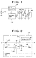
- FIG. 1 illustrates a circuit construction of a power supply system according to a preferred embodiment.
- a battery 10 e.g., of 36 V
- supplies power to another battery 17 e.g., of 12 V
- the battery 10 may also drive a motor generator (now shown) and the like.
- the battery 17 is connected to a load 18 and a bulb 22, and drives these elements.
- the battery 10 and the battery 17 can be installed in a trunk room or an engine room of a vehicle.
- the operation of the DC-DC converter 12 is controlled by a control unit 14. That is, the control unit 14 determines an ambient temperature of the battery 17, which is to be charged, based on a detection signal from a thermister 16.
- the control unit 14 controls the DC-DC converter 12 in such a manner that the charging voltage increases with decreases in the ambient temperature of the battery 17 so as to charge the battery 17 when necessary.
- the bulb 22 connected to the battery 17 deteriorates in brightness and the length of service life if a voltage exceeding a rated voltage (e.g., 14 V) of the bulb 22 is applied thereto.
- a rated voltage e.g. 14 V
- the control unit 14 controls the DC-DC converter 12 so that a voltage exceeding the rated voltage is not applied to the bulb 22 during the charging of the battery 17.
- the DC-DC converter 12 and the control unit 14 function as means for charging the battery 17.
- terminal A an input terminal of the control unit 14 to which the ambient temperature of the battery 17 detected by the thermister 16 is inputted
- terminal B an input terminal to which ON/OFF signals of a switch 20 (ON/OFF signals of the bulb 22) are inputted
- terminal C a terminal from which a control signal is outputted to the DC-DC converter 12
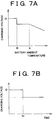
- FIG. 2 illustrates a circuit construction of the control unit 14.
- the control unit 14 includes a regulator 14a, a switch 14b, a power supply 14c, and diodes 14d, 14e.
- the regulator 14a is connected to the terminal A, and restricts a voltage signal from the thermister 16 that corresponds to the temperature into a predetermined voltage range.
- the input signal to the terminal A restricted by the regulator 14a is outputted to the terminal C via the diode 14d.
- FIG. 3 indicates the input voltage of the terminal A restricted by the regulator 14a.
- the horizontal axis indicates the ambient temperature (°C) of the battery 17 detected by the thermister 16, and the vertical axis indicates the voltage of the terminal A after restriction by the regulator 14a.
- the voltage is controlled so that the terminal A voltage monotonously increases as in Va, Vb, and then Vc (Va ⁇ Vb ⁇ Vc).
- the switch 14b shown in FIG. 2 is a switch, such as a relay or the like, in which a contact is selected based on the ON/OFF signal of the bulb 22 inputted from the terminal B. More specifically, when the bulb 22 is off, an open contact a is selected. When the bulb 22 is on, a contact b is selected.
- the switch 14b is connected to the power supply 14c and voltage divider resistors, and is supplied with a constant voltage Vb. Therefore, when the contact a of the switch 14b is selected, the switch 14b outputs zero volt (0 V). When the contact b is selected, the switch 14b outputs the contact voltage Vb.
- the output of the switch 14b is connected to the terminal C via the diode 14e in parallel with the diode 14d.
- a control voltage is outputted to the terminal C as described below (TABLE 1), in accordance with the ON/OFF state of the bulb 22 and the ambient temperature of the battery 17, that is, the input voltage at the terminal A.
- the switch 14b is controlled to switch to the open contact a, so that the voltage from the terminal A restricted by the regulator 14a, that is, a voltage of Va to Vc in accordance with the battery ambient temperature, is outputted from the terminal C.
- a voltage signal corresponding to the ambient temperature of the battery 17 is outputted from the terminal C of the control unit 14.
- the bulb 22 is on and the battery ambient temperature is relatively low (-Ta to Ta)
- a constant voltage signal is outputted from the terminal C.
- the ambient temperature is relatively high (Ta to Tb)
- a voltage signal corresponding to the ambient temperature is outputted from the terminal C, and is supplied to the DC-DC converter 12.
- the DC-DC converter 12 converts the DC voltage from the battery 10.
- the converted DC voltage is supplied to the load 18 and the bulb 22.
- the control voltage is Vb (constant)
- the DC-DC converter 12 outputs a contact voltage (Ve) corresponding to the constant control voltage.
- the control voltage varies within the range of Va to Vc
- the DC-DC converter 12 outputs a voltage of Vf to Vd in inverse proportion to the control voltage, where Vd ⁇ Ve ⁇ Vf.
- FIG. 4 indicates a relationship between the control voltage from the control unit 14 (terminal C voltage) and the output voltage of the DC-DC converter 12.
- the control unit 14 outputs a control voltage of Va to Vc.
- the DC-DC converter 12 outputs a voltage of Vf to Vd in inverse proportion to the control voltage. More specifically, the output voltage of the DC-DC converter 12 monotonously decreases with increases in the control voltage from the control unit 14. That is, the output voltage of the DC-DC converter 12 increases with decreases in the ambient temperature of the thermister 16. In this manner, the battery 17 is efficiently charged. Since the bulb 22 is off, that is, not connected to the circuit, the characteristics of the bulb 22 do not deteriorate even if the charging voltage exceeds the rated voltage of the bulb 22 (e.g., 14 V).
- the constant control voltage (Vb) is outputted if the ambient temperature of the battery 17 is low (-Ta to Ta), and the DC-DC converter 12 charges the battery 17 by outputting a constant voltage at or near the rated voltage of the load (e.g., 14 V) to the battery 17 and the bulb 22. If the battery ambient temperature is within the range of Ta to Tb, a control voltage of Vb to Vc is outputted, so that the DC-DC converter 12 charges the battery 17 by outputting a voltage that gradually decreases from the maximum value of the rated voltage (e.g., 14 V) with increases in the control voltage.
- the charging voltage for the battery 17 is reduced to the rated voltage of the bulb 22, so that the battery 17 can be charged without degrading the characteristics of the bulb 22.
- the battery 17 is charged with the rated voltage of the bulb 22, for example, 14V
- the optimal charging voltage for the battery 17 exceeds the rated voltage of the bulb 22
- a voltage e.g., 12 V
- the charging voltage may be temporarily raised at a predetermined timing.
- FIG. 5 illustrates a circuit construction according to another embodiment.
- a battery 17 is connected to a bulb 22 and to a power generator 24 for charging the battery 17.
- the operation of the power generator 24 is controlled by a control unit 26.
- the control unit 26 is formed by a microcomputer.
- the control unit 26 inputs a battery temperature and a battery voltage VB, and drives the power generator 24 so as to charge the battery 17 with a charging voltage in accordance with the temperature of the battery 17. However, if the battery 17 is charged with a voltage that exceeds the rated voltage of the bulb 22, the characteristics of the bulb 22 deteriorate.
- the control unit 26 curbs the deteriorations in characteristics of the bulb 22 by limiting the duration of charging the battery 17 with such a high voltage to a certain duration, and reducing the charging voltage to the rated voltage of the bulb 22 for the rest of the charging duration.
- the power generator 24 and the control unit 26 function as means for charging the battery 17.
- FIG. 6 shows a flowchart of processing executed by the control unit 26 in this embodiment.
- the control unit 26 first determines whether the lamp switch is on, that is, whether the bulb 22 is on (S101). If the bulb 22 is off, the control unit 26 controls the power generator 24 so as to charge the battery 17 with a voltage in accordance with the ambient temperature of the battery 17 (S107) since in that case, the charging of the battery 17 does not degrade the characteristics of the bulb 22. Conversely, if the bulb 22 is on, the control unit 26 determines whether the battery ambient temperature is at most a value A (S102). If the battery ambient temperature is at most A, the control unit 26 determines whether the battery temperature is at most B (A > B) (S103).
- the control unit 26 determines whether a predetermined time has elapsed following the start of the charging (S104) because in that case the battery 17 needs to be charged with a voltage exceeding the rated voltage of the bulb 22. As is apparent from the above description, this determination is performed in order to limit the duration of applying a voltage exceeding the rated voltage to the predetermined duration.
- the control unit 26 controls the power generator 24 so as to charge the battery 17 with a charging voltage in accordance with the temperature of the battery 17, for example, a charging voltage D (S106).
- the control unit 26 controls the power generator 24 so as to reduce the charging voltage to a voltage C that is equal to or lower than the rated voltage (S105), thereby curbing the deteriorations in characteristics of the bulb 22. It is preferred that the aforementioned predetermined time be set in accordance with the degree of deterioration in characteristics of the load connected to the battery 17.
- the control unit 26 sets the charging voltage to the value C equal to or lower than the rated voltage to charge the battery 17 even if the optimal charging voltage exceeds the rated voltage (S105). Therefore, when the battery temperature exceeds B before the predetermined time elapses following the start of charging, the charging voltage is changed from D to C. Furthermore, if the battery temperature is higher than A, the control unit 26 controls the power generator 24 so as to charge the battery 17 with a voltage in accordance with the battery temperature (S107) since the voltage needed to charge the battery 17 is lower than or equal to the rated voltage of the bulb 22.
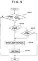
- FIG. 7A indicates a relationship between the battery ambient temperature and the charging voltage.
- FIG. 7B indicates a relationship between the charging voltage and the elapsed time, respectively.
- the D-voltage higher than the rated voltage instead of setting the D-voltage higher than the rated voltage to a constant value, it is also possible to vary the D-voltage in accordance with the ambient temperature of the battery 17. Furthermore, it is also possible to omit the use of the temperature thresholds A, B, and simply vary the charging voltage in accordance with the battery ambient temperature, and set the duration of applying the D-voltage higher than the rated voltage to a constant duration and, after that, charge the battery 17 with the C-voltage equal to or lower than the rated voltage (the value C may be varied in accordance with the battery temperature).
- FIG. 8 illustrates a circuit construction according to still another embodiment.
- the construction shown in FIG. 8 differs from the construction shown in FIG. 5 in that a switch 19 is provided for connecting a bulb 22 to the circuit, and in that a control unit 28 controls the switching of the switch 19 to disconnect the bulb 22 to and connect it to the circuit based on the battery temperature and various sensor signals.
- the various sensor signals are signals that are needed to determine whether it is necessary to operate the bulb 22.
- the sensor signals may be, for example, a detection signal indicating whether the vehicle is running, a detection signal indicating whether the outside world is light or dark.
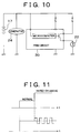
- FIG. 9 shows a flowchart of processing executed by the control unit 28 in this embodiment.
- the control unit 28 determines whether the charging voltage determined in accordance with the temperature of the battery 17 is higher than the rated voltage of the bulb 22 (S201). If the temperature of the battery 17 is low so that the charging voltage exceeds the rated voltage, the control unit 28 determines whether the operation of the bulb 22 is needed based on various sensor signals. That is, the control unit 28 determines whether the vehicle is at a stop (S202). If the vehicle is running, the control unit 28 determines whether the outside is light (S203). When the vehicle is at a stop or when the outside is light, the control unit 28 opens the switch 19 since there is no need to operate the bulb 22 (S204, S205).
- the bulb 22 is disconnected from the circuit, so that even though the battery 17 is charged with a charging voltage from the power generator 24 that is higher than the rated voltage, the bulb 22 is not affected while the battery 17 is efficiently charged.
- the bulb 22 is preferable to prevent deteriorations in characteristics of the bulb 22 by varying the charging voltage by, for example, a method described above, because the bulb 22 cannot be disconnected in that case.
- FIG. 10 shows a circuit construction according to a further embodiment.
- This circuit construction is similar to the constructions in the foregoing embodiments in that a bulb 22, that is, a load, is connected to a battery 17, and in that the battery 17 is connected so as to be charged by a power generator 24.
- a PWM (pulse width modulation) circuit 30 that includes a microcomputer and a modulation transistor is provided as means for reducing the voltage applied to the load, between the bulb 22 and the power generator 24.
- the charging voltage from the power generator 24 is modulated in pulse width by the PWM circuit 30 before being supplied to the bulb 22.
- the PWM circuit 30 does not modulate the charging voltage.
- the PWM circuit 30 modulates the charging voltage in pulse width so that the effective voltage is reduced to or below the rated voltage, before supplying the voltage to the bulb 22.
- FIG. 11 is a timing chart of pulse width modulation performed by the PWM circuit 30.
- VA upper stage
- VB lower stage
- the power generator 24 charges the battery 17 by outputting a voltage in accordance with the ambient temperature of the battery 17.
- the ambient temperature of the battery 17 is relatively high so that a normal voltage, that is, a voltage lower than or equal to the rated voltage of the bulb 22, is used to charge the battery 17, the voltage from the power generator 24 is not modulated, but is simply supplied to the bulb 22.
- the PWM circuit 30 modulates the voltage from the power generator 24 in pulse width at a predetermined duty ratio, before supplying the voltage to the bulb 22.
- the pulse width modulation is set so that the effective voltage becomes as indicated by a one-dot chain line in the chart, that is, becomes equal to or lower than the rated voltage of the bulb 22.
- the voltage supplied to the bulb 22 is reduced through pulse width modulation, it is also possible to provide a DC-DC converter between the power generator 24 and the bulb 22 and use the DC-DC converter to reduce the voltage to be supplied to the bulb 22 to or below the rated voltage of the bulb 22.
- the invention makes it possible to curb deteriorations in characteristics of a load connected to a battery while efficiently charging the battery.
Landscapes
- Engineering & Computer Science (AREA)
- Power Engineering (AREA)
- Transportation (AREA)
- Mechanical Engineering (AREA)
- Life Sciences & Earth Sciences (AREA)
- Sustainable Development (AREA)
- Sustainable Energy (AREA)
- Charge And Discharge Circuits For Batteries Or The Like (AREA)
- Secondary Cells (AREA)
Abstract
Description
| Bulb | Battery ambient temperature | Output voltage of terminal C |
| ON | -Ta to Ta | Vb (constant) |
| ON | Ta to Tb | Vb to Vc |
| OFF | -Ta to Ta | Va to Vb |
| OFF | Ta to Tb | Vb to Vc |
Claims (12)
- A power supply system comprising a battery (17), an electric circuit including the battery (17) and a load (22), and charging means (10, 12, 14) that is connected to the electric circuit which charges the battery by supplying a required voltage, the system characterized in that: the charging means (10, 12, 14) changes a voltage that is supplied to at least a portion of the electric circuit when the required voltage is higher than a rated voltage above which a characteristic of the load (22) deteriorates.
- A power supply system according to claim 1, wherein the charging means (10, 12, 14) reduces the voltage to equal to the rated voltage or less when the required voltage is higher than the rated voltage.
- A power supply system according to claim 2, wherein the charging means (10, 12, 14) reduces the voltage during a predetermined time.
- A power supply system according to claim 1, wherein the charging means (10, 12, 14) detects a operation requirement for the load (22), and electrically isolates the load from the electric circuit based on the operation requirement for the load (22) when the required voltage is higher than the rated voltage.
- A power supply system according to claim 1, wherein the charging means (10, 12, 14) reduces a voltage that is supplied to the load to equal to the rated voltage or less when the required voltage is higher than the rated voltage.
- A power supply system according to any one of claims 1 to 5, wherein the requirement voltage is determined based on a temperature of the battery.
- A control method for power supply system includes a electric circuit having a battery (17) and a load (22) that is connected to the battery, and that deteriorates in a characteristic if a voltage exceeding a rated voltage of the load (22) is applied thereto, the method characterized by comprising;determining a required voltage that is applied to charge the battery;changing a voltage that is supplied to at least a portion of the electric circuit when the required voltage is higher than the rated voltage.
- A method according to claim 7, wherein the changing step includes reducing the voltage to equal to the rated voltage or less when the required voltage is higher than the rated voltage.
- A method according to claim 8, wherein the voltage is reduced during a predetermined time.
- A method according to claim 7 characterized by further comprising:detecting a operation requirement for the load;electrically isolating the load from the electric circuit based on the operation requirement for the load when the required voltage is higher than the rated voltage.
- A method according to claim 7, wherein the changing step includes reducing a voltage that is supplied to the load to equal to the rated voltage or less when the required voltage is higher than the rated voltage.
- A method according to any one of claim 7 to 11, wherein the requirement voltage is determined based on a temperature of the battery.
Applications Claiming Priority (2)
| Application Number | Priority Date | Filing Date | Title |
|---|---|---|---|
| JP32056799 | 1999-11-11 | ||
| JP32056799A JP3552614B2 (en) | 1999-11-11 | 1999-11-11 | Power supply circuit |
Publications (3)
| Publication Number | Publication Date |
|---|---|
| EP1100174A2 true EP1100174A2 (en) | 2001-05-16 |
| EP1100174A3 EP1100174A3 (en) | 2003-11-26 |
| EP1100174B1 EP1100174B1 (en) | 2006-03-01 |
Family
ID=18122887
Family Applications (1)
| Application Number | Title | Priority Date | Filing Date |
|---|---|---|---|
| EP00124527A Expired - Lifetime EP1100174B1 (en) | 1999-11-11 | 2000-11-09 | Power supply system and control method for the system |
Country Status (4)
| Country | Link |
|---|---|
| US (1) | US6329791B1 (en) |
| EP (1) | EP1100174B1 (en) |
| JP (1) | JP3552614B2 (en) |
| DE (1) | DE60026217T2 (en) |
Cited By (2)
| Publication number | Priority date | Publication date | Assignee | Title |
|---|---|---|---|---|
| CN103606721A (en) * | 2013-11-20 | 2014-02-26 | 杨成云 | Cooling and thermal insulation battery device |
| CN111031636A (en) * | 2019-12-31 | 2020-04-17 | 鹰潭阳光照明有限公司 | Light-operated LED lamp circuit capable of setting working mode |
Families Citing this family (7)
| Publication number | Priority date | Publication date | Assignee | Title |
|---|---|---|---|---|
| DE60113832T2 (en) * | 2001-02-14 | 2006-07-06 | Toyota Jidosha K.K., Toyota | DRIVE DEVICE AND CONTROL PROCEDURE, STORAGE MEDIUM AND PROGRAM FOR THE DRIVE DEVICE |
| JP3692993B2 (en) * | 2001-10-04 | 2005-09-07 | トヨタ自動車株式会社 | DRIVE DEVICE AND POWER OUTPUT DEVICE |
| JP4379412B2 (en) * | 2005-12-05 | 2009-12-09 | トヨタ自動車株式会社 | Power steering power control device |
| JP4811301B2 (en) * | 2007-03-06 | 2011-11-09 | トヨタ自動車株式会社 | Secondary battery input / output control device and vehicle |
| EP3068010A1 (en) * | 2015-03-10 | 2016-09-14 | HILTI Aktiengesellschaft | Battery charger and charging system that can be operated on mains power |
| JP7454445B2 (en) * | 2020-05-11 | 2024-03-22 | 新電元工業株式会社 | Electric vehicle charging device |
| US20240010090A1 (en) * | 2020-10-29 | 2024-01-11 | Tvs Motor Company Limited | A system and method of fast charging a battery using combined constant current and constant voltage charging |
Family Cites Families (5)
| Publication number | Priority date | Publication date | Assignee | Title |
|---|---|---|---|---|
| US4780619A (en) * | 1986-08-15 | 1988-10-25 | General Motors Corporation | High DC voltage power supply for motor vehicle electrical system |
| JPH04351436A (en) | 1991-05-29 | 1992-12-07 | Shin Kobe Electric Mach Co Ltd | Battery charging control method for vehicle |
| JPH06225599A (en) * | 1992-10-14 | 1994-08-12 | Ford Motor Co | Output power controller of generator for car |
| JPH08336201A (en) * | 1995-06-07 | 1996-12-17 | Nissan Motor Co Ltd | Low voltage battery condition detector |
| JP3491714B2 (en) * | 1995-06-14 | 2004-01-26 | 本田技研工業株式会社 | Battery over-discharge prevention device for electric vehicles |
-
1999
- 1999-11-11 JP JP32056799A patent/JP3552614B2/en not_active Expired - Fee Related
-
2000
- 2000-11-09 US US09/708,710 patent/US6329791B1/en not_active Expired - Fee Related
- 2000-11-09 EP EP00124527A patent/EP1100174B1/en not_active Expired - Lifetime
- 2000-11-09 DE DE60026217T patent/DE60026217T2/en not_active Expired - Fee Related
Cited By (4)
| Publication number | Priority date | Publication date | Assignee | Title |
|---|---|---|---|---|
| CN103606721A (en) * | 2013-11-20 | 2014-02-26 | 杨成云 | Cooling and thermal insulation battery device |
| CN103606721B (en) * | 2013-11-20 | 2015-11-18 | 杨成云 | A kind of cell apparatus of insulation of lowering the temperature |
| CN111031636A (en) * | 2019-12-31 | 2020-04-17 | 鹰潭阳光照明有限公司 | Light-operated LED lamp circuit capable of setting working mode |
| CN111031636B (en) * | 2019-12-31 | 2022-05-27 | 鹰潭阳光照明有限公司 | Light-operated LED lamp circuit capable of setting working mode |
Also Published As
| Publication number | Publication date |
|---|---|
| JP3552614B2 (en) | 2004-08-11 |
| DE60026217T2 (en) | 2006-11-16 |
| JP2001136678A (en) | 2001-05-18 |
| EP1100174B1 (en) | 2006-03-01 |
| DE60026217D1 (en) | 2006-04-27 |
| EP1100174A3 (en) | 2003-11-26 |
| US6329791B1 (en) | 2001-12-11 |
Similar Documents
| Publication | Publication Date | Title |
|---|---|---|
| US8760832B2 (en) | Load circuit protection device | |
| US7053500B2 (en) | Automotive electric power unit | |
| KR0182305B1 (en) | Control system of alternator | |
| US6313546B1 (en) | Power supply assembly for a vehicle | |
| US8390145B2 (en) | Battery isolator unit | |
| US6198258B1 (en) | DC-DC converter capable of soft starting function by slowly raising reference voltage | |
| EP1120880A2 (en) | Power supply circuit | |
| US6476315B2 (en) | Solar system for a motor vehicle | |
| US20100090529A1 (en) | Electric power source device | |
| US11329474B2 (en) | Switching controller with adaptive overheating protection | |
| US20010007419A1 (en) | Power supply circuit | |
| US6812672B2 (en) | Electric charge control device and load driving device using the same | |
| US20040164705A1 (en) | Onboard power supply system | |
| US7746027B2 (en) | Electric power controller for vehicle mounting | |
| JP2008511277A (en) | Voltage controller with overvoltage protection | |
| US6329791B1 (en) | Power supply system and control method for the system | |
| JP2001069751A (en) | Buck converter | |
| JP2000253594A (en) | Apparatus for transmitting charging current between batteries | |
| US20030145256A1 (en) | Error detection device for a multi-voltage vehicle power supply | |
| US7417407B1 (en) | Circuit with a switch for charging a battery in a battery capacitor circuit | |
| JPS62173901A (en) | Output control unit of dc/dc converter for electric vehicle | |
| KR101872831B1 (en) | System and method for supplying power to external device of vehicle | |
| US12062979B2 (en) | Drive device | |
| AU2009243458B2 (en) | An improved battery isolator unit | |
| KR100340875B1 (en) | Protection circuit of over charge of battery |
Legal Events
| Date | Code | Title | Description |
|---|---|---|---|
| PUAI | Public reference made under article 153(3) epc to a published international application that has entered the european phase |
Free format text: ORIGINAL CODE: 0009012 |
|
| 17P | Request for examination filed |
Effective date: 20001124 |
|
| AK | Designated contracting states |
Kind code of ref document: A2 Designated state(s): AT BE CH CY DE DK ES FI FR GB GR IE IT LI LU MC NL PT SE TR |
|
| AX | Request for extension of the european patent |
Free format text: AL;LT;LV;MK;RO;SI |
|
| PUAL | Search report despatched |
Free format text: ORIGINAL CODE: 0009013 |
|
| AK | Designated contracting states |
Kind code of ref document: A3 Designated state(s): AT BE CH CY DE DK ES FI FR GB GR IE IT LI LU MC NL PT SE TR |
|
| AX | Request for extension of the european patent |
Extension state: AL LT LV MK RO SI |
|
| RIC1 | Information provided on ipc code assigned before grant |
Ipc: 7H 02J 7/00 A Ipc: 7H 02J 7/14 B |
|
| 17Q | First examination report despatched |
Effective date: 20040216 |
|
| AKX | Designation fees paid |
Designated state(s): DE FR GB |
|
| GRAP | Despatch of communication of intention to grant a patent |
Free format text: ORIGINAL CODE: EPIDOSNIGR1 |
|
| GRAS | Grant fee paid |
Free format text: ORIGINAL CODE: EPIDOSNIGR3 |
|
| GRAA | (expected) grant |
Free format text: ORIGINAL CODE: 0009210 |
|
| AK | Designated contracting states |
Kind code of ref document: B1 Designated state(s): DE FR GB |
|
| REG | Reference to a national code |
Ref country code: GB Ref legal event code: FG4D |
|
| REF | Corresponds to: |
Ref document number: 60026217 Country of ref document: DE Date of ref document: 20060427 Kind code of ref document: P |
|
| ET | Fr: translation filed | ||
| PLBE | No opposition filed within time limit |
Free format text: ORIGINAL CODE: 0009261 |
|
| STAA | Information on the status of an ep patent application or granted ep patent |
Free format text: STATUS: NO OPPOSITION FILED WITHIN TIME LIMIT |
|
| 26N | No opposition filed |
Effective date: 20061204 |
|
| PGFP | Annual fee paid to national office [announced via postgrant information from national office to epo] |
Ref country code: DE Payment date: 20081107 Year of fee payment: 9 |
|
| PGFP | Annual fee paid to national office [announced via postgrant information from national office to epo] |
Ref country code: FR Payment date: 20081112 Year of fee payment: 9 |
|
| PGFP | Annual fee paid to national office [announced via postgrant information from national office to epo] |
Ref country code: GB Payment date: 20081105 Year of fee payment: 9 |
|
| GBPC | Gb: european patent ceased through non-payment of renewal fee |
Effective date: 20091109 |
|
| REG | Reference to a national code |
Ref country code: FR Ref legal event code: ST Effective date: 20100730 |
|
| PG25 | Lapsed in a contracting state [announced via postgrant information from national office to epo] |
Ref country code: FR Free format text: LAPSE BECAUSE OF NON-PAYMENT OF DUE FEES Effective date: 20091130 |
|
| PG25 | Lapsed in a contracting state [announced via postgrant information from national office to epo] |
Ref country code: DE Free format text: LAPSE BECAUSE OF NON-PAYMENT OF DUE FEES Effective date: 20100601 |
|
| PG25 | Lapsed in a contracting state [announced via postgrant information from national office to epo] |
Ref country code: GB Free format text: LAPSE BECAUSE OF NON-PAYMENT OF DUE FEES Effective date: 20091109 |