The present invention relates to a plastic
optical alignment sleeve for conversion connector
which directly holds and connects optical fiber cords
containing single-mode optical fibers and having
ferrules with different outer diameters.
Advances in the optical communication technology
are making a variety of communication services
available to individual homes through optical fibers.
The realization of an optical communication network
for subscribers requires economically viable optical
connectors.
To connect optical fibers used for optical
communication, the conventional practice involves
aligning inside a sleeve 02 two ferrules 01A, 01B,
each sleeved over an optical fiber cord, as shown in
Fig. 1. Reference numbers 03A, 03B represent optical
fiber cords.
Among the commonly used sleeves 02 for aligning
the ferrules 01A, 01B is a split sleeve 05, a thick
hollow cylindrical sleeve with a slit 04 extending
parallel to the center axis thereof, as shown in Fig.
2. Such a split sleeve 05 is made of metal materials
such as phosphor bronze or ceramics such as zirconia.
The inner diameter of a through-hole of the split
sleeve 05 is made smaller than the outer diameter of
the ferrules 01A, 01B holding the optical fibers, so
that when the ferrules 01A, 01B are inserted into the
split sleeve 05, a gap is not easily formed between
the ferrules 01A, 01B and the through-hole 06.
As for ferrules used in optical connectors, they
are made of ceramics and polished to a high precision
to realize a required dimensional accuracy for precise
connection between the inserted optical fibers. An
SC-type ferrule that has been in wide use is 2.499 mm
in outer diameter. For higher density and cost-effectiveness,
a narrow diameter ferrule is also used,
a typical example of which is an MU-type ferrule with
an outer diameter of 1.249 mm about one-half the
conventional size.
Under these circumstances, a conversion connector
is used to connect two ferrules with different outer
diameters. With this conversion connector, as shown
in Fig. 3, two ferrules 07A, 07B with different outer
diameters, each having optical fibers inserted therein,
are aligned in a sleeve 08 to connect the optical
fibers. Reference numbers 09A, 09B represent optical
fiber cords.
As the sleeve 08 for aligning the ferrules 07A,
07B, as shown in Fig. 4, a split sleeve 12 is used,
which consists of two thick hollow cylindrical sleeves
10A, 10B cut with a slit 11 extending parallel to the
center axis of the cylinders. This split sleeve 12
has at an intermediate portion a joint part 13 for
connecting the left and right cylindrical sleeves 10A,
10B with different sizes, with the slit 11 extending
through the left and right cylindrical sleeves and the
joint part.
The split sleeve 12 shown in Fig. 4, however, is
very complex in geometry, with the left and right
cylinders having different dimensions. So, it cannot
be manufactured by the method used to fabricate the
split sleeve 05 of Fig. 2. Hence, the split sleeve 12
is manufactured by cutting a metallic material such as
phosphor bronze to a high precision. This in turn
leads to a very high cost, hindering economical
production of the conversion connector. When the
ferrules are inserted into the split sleeve 12, the
portion near the slit 11 deforms greatly, resulting in
the axes of ferrules with different outer diameters
easily shifting from each other, making the
dimensional design difficult.
The present invention has been accomplished in
light of the above problems to provide a plastic
sleeve for conversion connector which directly holds
and connects optical fiber cords having single-mode
optical fibers inserted therein and including ferrules
of different outer diameters. More specifically, it
is an object of the present invention to provide a
plastic sleeve for conversion connector with high
dimensional accuracy, large mechanical strength, and
excellent reliability and cost-effectiveness.
Accordingly, the first invention provides a
plastic optical alignment sleeve for conversion
connector, which is installed in an adapter used to
connect optical fiber cords each having optical fibers
inserted therein and which optically connects the
optical fibers by inserting ferrules with different
outer diameters attached to free ends of the optical
fiber cords into the sleeve from its left and right
ends, the plastic optical alignment sleeve in its
basic geometry comprising: left and right thick hollow
cylinders differing from each other in inner diameter
and thickness; and a joint part formed at an
intermediate portion of the sleeve for connecting the
left and right thick hollow cylinders with different
dimensions; wherein the plastic sleeve is formed of a
noncrystalline thermoplastic resin or thermosetting
resin or of a resin compound; wherein a slit is formed
through the left and right thick hollow cylinders and
the joint part.
The second invention provides a plastic optical
alignment sleeve for conversion connector according to
the first invention, wherein one of the thick hollow
cylinders of the plastic sleeve has an inner diameter
of between approximately 1.243 mm and 1.248 mm and a
thickness of between approximately 0.2 mm and 0.7 mm
and the other thick hollow cylinder has an inner
diameter of between approximately 2.475 mm and 2.497
mm and a thickness of between approximately 0.4 mm and
0.8 mm.
The third invention provides a plastic optical
alignment sleeve for conversion connector according to
the first invention, wherein the joint part of the
plastic sleeve is shaped like a truncated hollow cone
whose angle of elevation as seen from the small-diameter
thick hollow cylinder is in a range of
between 30 degrees and 75 degrees, and the thickness
of the joint part is in a range of between
approximately 0.2 mm and 0.7 mm.
The fourth invention provides a plastic optical
alignment sleeve for conversion connector according to
the first invention, wherein the noncrystalline
thermoplastic resin or resin compound is one of resins
including at least polyethersulfone, polysulfone and
polyetherimide, or a resin compound including one of
these resins and an inorganic filler or carbon fiber,
and wherein the thermosetting resin or resin compound
is epoxy resin or epoxy resin compound including
silica powder.
The fifth invention provides a plastic optical
alignment sleeve for conversion connector according to
the second invention, wherein the joint part of the
plastic sleeve is shaped like a truncated hollow cone
whose angle of elevation as seen from the small-diameter
thick hollow cylinder is in a range of
between 30 degrees and 75 degrees, and the thickness
of the joint part is in a range of between
approximately 0.2 mm and 0.7 mm.
The sixth invention provides a plastic optical
alignment sleeve for conversion connector according to
the second invention, wherein the noncrystalline
thermoplastic resin or resin compound is one of resins
including at least polyethersulfone, polysulfone and
polyetherimide, or a resin compound including one of
these resins and an inorganic filler or carbon fiber,
and wherein the thermosetting resin or resin compound
is epoxy resin or epoxy resin compound including
silica powder.
The seventh invention provides a plastic optical
alignment sleeve for conversion connector according to
the third invention, wherein the noncrystalline
thermoplastic resin or resin compound is one of resins
including at least polyethersulfone, polysulfone and
polyetherimide, or a resin compound including one of
these resins and an inorganic filler or carbon fiber,
and wherein the thermosetting resin or resin compound
is epoxy resin or epoxy resin compound including
silica powder.
The eighth invention provides a plastic optical
alignment sleeve for conversion connector according to
the fifth invention, wherein the noncrystalline
thermoplastic resin or resin compound is one of resins
including at least polyethersulfone, polysulfone and
polyetherimide, or a resin compound including one of
these resins and an inorganic filler or carbon fiber,
and wherein the thermosetting resin or resin compound
is epoxy resin or epoxy resin compound including
silica powder.
The ninth invention provides a plastic optical
alignment sleeve for conversion connector, which is
installed in an adapter used to connect optical fiber
cords each having optical fibers inserted therein and
which optically connects the optical fibers by
inserting ferrules with different outer diameters
attached to free ends of the optical fiber cords into
the sleeve from its left and right ends, the plastic
optical alignment sleeve in its basic geometry
comprising: left and right thick hollow cylinders
differing from each other in inner diameter and
thickness; and a joint part formed at an intermediate
portion of the sleeve for connecting the left and
right thick hollow cylinders with different
dimensions; wherein the plastic sleeve is formed of a
noncrystalline thermoplastic resin or thermosetting
resin or of a resin compound; wherein the left and
right thick hollow cylinders have inner surfaces of
the same cylindrical shape as their outer surfaces or
a polygonal prism shape enclosed by straight lines,
and also have at least three planes on the inner
surface side that contact the ferrule; wherein a
diameter (d) of a virtual cylinder connecting those
points at which the inner surface contacts the ferrule
is smaller than an outer diameter of the ferrule.
The tenth invention provides a plastic optical
alignment sleeve for conversion connector according to
the ninth invention, wherein the diameter (d) of the
virtual cylinder connecting those points on one of the
thick hollow cylinders that contact the ferrule is in
a range of between approximately 1.246 mm and 1.248 mm
and the thickness of the thinnest part of the virtual
cylinder is in a range of between approximately 0.2 mm
and 0.3 mm, and wherein the diameter (d) of the
virtual cylinder connecting those points on the other
thick hollow cylinder that contact the ferrule is in a
range of between approximately 2.490 mm and 2.498 mm
and the thickness of the thinnest part of the virtual
cylinder is in a range of between approximately 0.3 mm
and 0.8 mm.
The eleventh invention provides a plastic optical
alignment sleeve for conversion connector according to
the ninth invention, wherein the joint part of the
plastic sleeve is shaped like a truncated hollow cone
whose angle of elevation as seen from the small-diameter
thick hollow cylinder is in a range of
between 30 degrees and 75 degrees, and the thickness
of the thinnest part of the joint part is in a arrange
of between approximately 0.2 mm and 0.3 mm.
The twelfth invention provides a plastic optical
alignment sleeve for conversion connector according to
ninth invention, wherein the noncrystalline
thermoplastic resin or resin compound is one of resins
including at least polyethersulfone, polysulfone and
polyetherimide, or a resin compound including one of
these resins and an inorganic filler or carbon fiber,
and wherein the thermosetting resin or resin compound
is epoxy resin or epoxy resin compound including
silica powder.
The thirteenth invention provides a plastic
optical alignment sleeve for conversion connector
according to the tenth invention, wherein the joint
part of the plastic sleeve is shaped like a truncated
hollow cone whose angle of elevation as seen from the
small-diameter thick hollow cylinder is in a range of
between 30 degrees and 75 degrees, and the thickness
of the thinnest part of the joint part is in a arrange
of between approximately 0.2 mm and 0.3 mm.
The fourteenth invention provides a plastic
optical alignment sleeve for conversion connector
according to the tenth invention, wherein the
noncrystalline thermoplastic resin or resin compound
is one of resins including at least polyethersulfone,
polysulfone and polyetherimide, or a resin compound
including one of these resins and an inorganic filler
or carbon fiber, and wherein the thermosetting resin
or resin compound is epoxy resin or epoxy resin
compound including silica powder.
The fifteenth invention provides a plastic
optical alignment sleeve for conversion connector
according to the eleventh invention, wherein the
noncrystalline thermoplastic resin or resin compound
is one of resins including at least polyethersulfone,
polysulfone and polyetherimide, or a resin compound
including one of these resins and an inorganic filler
or carbon fiber, and wherein the thermosetting resin
or resin compound is epoxy resin or epoxy resin
compound including silica powder.
The sixteenth invention provides a plastic
optical alignment sleeve for conversion connector
according to the thirteenth invention, wherein the
noncrystalline thermoplastic resin or resin compound
is one of resins including at least polyethersulfone,
polysulfone and polyetherimide, or a resin compound
including one of these resins and an inorganic filler
or carbon fiber, and wherein the thermosetting resin
or resin compound is epoxy resin or epoxy resin
compound including silica powder.
This invention has the advantage of being able to
provide a plastic sleeve for conversion connector with
excellent connection characteristic, reliability and
cost-effectiveness, which can be used to connect
optical fiber cords having single-mode optical fibers
inserted therein and including ferrules of different
outer diameters.
The above and other objects, features and
advantages of the present invention will become more
apparent from the following description of embodiments
thereof taken in conjunction with the accompanying
drawings.
Having studied the conventional methods and their
problems in detail, the inventors of this invention
have accomplished the invention in the following
process.
(1) Selection of Molding Material: In the molding
technology the selection of a molding material
constitutes the most important task.
Plastic materials that can be used instead of
metals or ceramic materials are normally called
engineering plastics and a variety of such materials
have been developed until recently. Our studies on
various engineering plastics have shown that, in
producing a resin or resin compound that meets the
mechanical strength, creep resistance, dimensional
stability against temperature and humidity variations,
and precision moldability required by the invention,
it is important to use noncrystalline resin as a basic
compound. Appropriate resins include, for example,
polyethersulfone (PES), polysulfone (PS) and
polyetherimide (PEI). This is because crystal resins
have been observed to have a problem that deformation
after molding and stress relaxation over a long period
of time are at levels that cannot be neglected.
These resins are classified as so-called
thermoplastic resins and become liquefied from the
solid state when heated above their melting points.
In this state the resins are flowed into a mold to
solidify, thus producing a molded product.
There is another type of resin, called a
thermosetting resin, which, in a heated state, does
not polymerize and remains completely liquefied. This
resin is flowed into a mold and heated for a
predetermined period of time to cause a crosslink
reaction, thus producing a molded product. It has
been found that among these thermosetting resins, an
epoxy resin is an appropriate choice for producing a
resin or resin compound that can satisfy the
mechanical strength, creep resistance, dimensional
stability against temperature and humidity variations,
and precision moldability required by the invention.
Among commonly known additives as inorganic
fillers for use in the resin of this invention are
glass fibers, potassium titanate whiskers, zinc oxide
and glass beads. Other known inorganic additives
include carbon fibers, graphite, Teflon beads, silica
powder and barium titanate. The inventors has found
that, of these additives, at least inorganic fillers
such as potassium titanate whiskers and zinc oxide or
carbon fibers need to be added to the thermoplastic
resin and at least silica powder to the thermosetting
resin in realizing this invention.
The amount of additive is determined in a range
that does not deteriorate the precision moldability of
the resin. It may be selected in the range of 20% to
70% or more preferably 30% to 60%.
It is also possible to add surface treating
agents and coloring agents for the additives, as
required.
(2) Selection of Inner Diameter and Thickness of
Split Sleeve
The plastic optical alignment split sleeve for
conversion connector of this invention that aligns
ferrules of different diameters has the construction
in which left and right thick hollow cylindrical
sleeves with different inner diameters and different
thicknesses are connected at the central joint part.
Fig. 5 shows an external view of the plastic
optical alignment split sleeve for conversion
connector of this invention and Fig. 6 shows its inner
structure. In this split sleeve 52, a cylindrical
sleeve for an MU-type ferrule 51A formed of a small-diameter
thick hollow cylinder and a cylindrical
sleeve for an SC-type ferrule 51B formed of a thick
hollow cylinder larger in diameter than the former are
joined together at a joint part 53, with a cut or slit
54 extending through the left and right thick hollow
cylinders and the joint part 53.
The SC-type ferrule 2.499 mm in outer diameter
has an allowable gauge retention force of 0.2-0.6 kgf
whereas the MU-type small-diameter ferrule 1.249 mm in
outer diameter has an allowable gauge retention force
of 0.1-0.25 kgf, smaller than that of the SC-type
ferrule.
The gauge retention force of the slit sleeve is
determined by the inner diameter and thickness. Hence,
to maintain high reliability of the split sleeve in
the conversion connector requires controlling the
inner diameter and thickness of the cylindrical
sleeves, into which ferrules are inserted, to
appropriate values to realize a proper gauge retention
force required of each ferrule.
When ferrules are inserted into the plastic
optical alignment split sleeve, the split sleeve
elastically deforms causing a stress in the sleeve.
Multiplying this stress with a friction coefficient of
the material can determine the gauge retention force.
First, consider a case in which an SC-type
ferrule 2.499 mm in outer diameter is inserted into
plastic split sleeves with a variety of inner
diameters.
The relation between the gauge retention force
produced and the thickness of the plastic split sleeve
is shown in Fig. 7. The allowable gauge retention
force of the SC-type ferrule is in the range of
between 0.2 kgf and 0.6 kgf. From Fig. 7 it is seen
that the plastic split sleeve that meets this
requirement needs to have an inner diameter of
approximately 2.475 mm to 2.497 mm and a thickness of
about 0.4 mm to 0.8 mm.
Next, consider a case where an MU-type ferrule
1.249 mm in outer diameter is inserted into plastic
split sleeves with a variety of inner diameters.
The relation between the gauge retention force
generated and the thickness of the plastic split
sleeve is shown in Fig. 8. The allowable gauge
retention force of the MU-type ferrule is in the range
of 0.1-0.25 kgf. From Fig. 8 it is seen that the
plastic split sleeve that meets this requirement needs
to have an inner diameter of approximately 1.243 mm to
1.248 mm and a thickness of about 0.2 mm to 0.7 mm.
The plastic optical alignment split sleeve for
conversion connector of this invention that aligns
ferrules of different diameters is made by selecting
an appropriate range of inner diameter and thickness
described above and combining left and right thick
hollow cylindrical sleeves 51A, 51B with different
inner diameters and different thicknesses.
It is a prerequisite that the left and right
cylindrical sleeves 51A, 51B with the slit 54 are
coaxial. Considering a difference in the amount of
material deformation, however, it is possible to
deliberately shift the center axes of the left and
right cylindrical sleeves 51A, 51B from each other.
(3) Structure of Joint Part
The structure of the joint part 53, which is
situated at an intermediate portion of the plastic
optical alignment split sleeve 52 for conversion
connector of the invention and which connects the left
and right thick hollow cylindrical sleeves 51A, 51B
with different dimensions, is very important in
securing a good connection between different-diameter
ferrules.
The joint part 53 for joining the left and right
cylindrical sleeves 51A, 51B with different inner
diameters and different thicknesses begins at the end
of the left small-diameter cylindrical sleeve 51A in
Fig. 6 and expands in diameter along a slope as it
extends over a predetermined length toward the right
large-diameter cylindrical sleeve 51B and then merges
with it. The joint part 53 has the same thickness as
the small-diameter cylindrical sleeve 51A, in the
range of about 0.2 mm to 0.7 mm.
The magnitude of slope of the joint part 53 is
related with the stress that is generated in the
plastic split sleeve 52 when different-diameter
ferrules are inserted.
Inside the plastic split sleeve 52 for conversion
connector, the different-diameter ferrules are joined
at the end of the cylindrical sleeve 51B of a larger
inner diameter. The stress that occurs in the plastic
split sleeve 52 is large in a portion of the large-inner-diameter
cylindrical sleeve 51B opposite the-slit
54, and becomes maximum at the end of the sleeve
51B near the connecting point. The relation between
the maximum stress occurring in the plastic split
sleeve 52 and the angle of elevation of the joint part
53 as seen from the small-diameter cylindrical sleeve
51A is shown in Fig. 9.
From Fig. 9 it is understood that the maximum
stress decreases as the angle of elevation decreases.
Applying an excessively large stress continuously is
not desirable considering a resulting creep. However,
setting too small an angle of elevation results in a
longer joint part 53 and therefore an increased
dimension of the conversion connector, which is not
desirable. Therefore, the angle of elevation of the
joint part 53 as seen from the small-diameter
cylindrical sleeve 51A should be set in the range of
30-75 degrees, or preferably 45-60 degrees.
With the above construction, it is possible to
provide the joint part 53 with a sufficient thickness
and guarantee the mechanical strength and creep
resistance required by this invention.
In the following, we will describe preferred
embodiments that exhibit advantageous characteristics
unique to the invention. It should be noted, however,
that the invention is not limited to these embodiments.
[Embodiment 1]
First, the following resin compounds were
prepared.
Cresol novolak type epoxy resin: 100 parts by weight
Phenol novolak type curing agent: 100 parts by weight
Silica powder (average particle diameter 10 µm): 500
parts by weight
The flexural modulus of this resin compound was
2,100 kg/mm
2 in ASTM standard. The anisotropy of the
resin was evaluated by the ratio of mold shrinkage
factors in the direction along the flow of the resin
and the direction at right angles thereto and found to
be as low as 1.0. The resin compound formed in this
manner was injection-molded into a plastic optical
alignment split
sleeve 52 for conversion connector
shaped as shown in Figs. 5 and 6 with the dimensions
of Table 1.
| Dimensions of the split sleeve for conversion connector in embodiment 1 |
| Item | Dimensional tolerance |
| Cylindrical sleeve for SC ferrule |
| Inner diameter | 2.495 ± 0.001 mm |
| Thickness | 0.760 ± 0.005 mm |
| Length | 5.7 ± 0.005 mm |
| Cylindrical sleeve for MU ferrule |
| Inner diameter | 1.246 ± 0.001 mm |
| Thickness | 0.400 ± 0.005 mm |
| Length | 2.9 ± 0.005 mm |
| Length of joint part | 0.5 ± 0.005 mm |
| Angle of elevation of joint part | 60° |
The conditions of injection molding were as shown
in Table 2. The inner diameter error, thickness error
and roundness error of the moldings are all within 1
µm and the smoothness of the inner surface was within
±0.1 µm.
| Conditions of injection molding |
| Item | Conditions |
| Drying of resin | Stored at room temperature in dry atmosphere |
| Cylinder | Rear portion | 35°C |
| temperature | Intermediate portion | 50°C |
| | Nozzle portion | 860°C |
| Mold temperature | 180°C |
| Injection pressure |
| | 400 kg/cm2 |
| Screw backpressure | 80 kg/cm2 |
| Retention pressure | 500 kg/cm2 |
| Injection rate | 20 mm/sec |
| Cycling time |
| | 60 seconds |
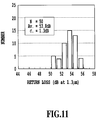
The measured gauge retention forces of the split
sleeve for the SC-type ferrule and MU-type ferrule
were 0.31 kgf and 0.12 kgf, respectively. The plastic
optical alignment split sleeve 52 manufactured in this
manner was assembled into a conversion connector, into
which the SC- and MU-type ferrules of zirconia were
inserted to measure the insertion loss and the return
loss. The end faces of the ferrules were polished
under the advanced physical contact (AdPC) polishing
conditions. The results are shown in Figs. 10 and 11,
which are satisfactory characteristics for the
connection of single-mode optical fibers.
Fig. 12 shows the result of a test in which the
zirconia ferrules were repetitively attached and
detached to and from the MU and SC sides of the
conversion connector. In Fig. 12 closed circles
represent the attaching/detaching on the SC side and
open circles the attaching/detaching on the MU side.
In the test where 500 attaching/detaching operations
were conducted, a change of loss occurred in only two
or fewer operations. This means that the connector
has a performance identical with those of the
currently used SC- and MU-type adapters.
Fig. 13 shows the result of a vibration test of
the conversion connector. The test conditions are as
follows.
- Sweep frequency range: 10-55 Hz
- Amplitude of sine wave: 0.75 mm
- Sweeping time: 2 minutes/cycle
During the 60 cycles in the test, changes in the
loss of X, Y and Z directions were about 0.05 dB,
which is well within the targeted range of
characteristics for the conversion connector. No
changes were observed in the return loss.
Fig. 14 shows the result of an impact test on the
conversion connector. The test conditions were as
follows.
- Impact peak value: 100 G
- Sine half-wave application time: 6 ms
- Number of tests: 10 times
In the 10 tests, no loss changes were observed in
the X, Y and Z directions, which satisfies the target
characteristic for the converter connector. Neither a
change in the return loss was observed.
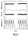
Fig. 15 shows the result of a temperature-humidity
cycling test on the conversion connector.
The test conditions were as follows.
- Temperature: -10°C to 20°C to 65°C
- Relative humidity: 93%
- Cycle time: 24 hours/cycle
- Number of cycles: 20 cycles
Fig. 15 shows the results of the first five
cycles and the last five cycles. In the 20 cycles of
the test, a loss change was about 0.1 dB and there was
almost no change in the return loss, which satisfies
the target characteristic of the conversion connector.
Fig. 16 shows the result of a temperature cycling
test on the conversion connector. The test conditions
were as follows.
- Temperature: -25°C to 25°C to 70°C
- Cycle time: 3.5 hours/cycle
- Number of cycles: 100 cycles
Fig. 16 shows the result of the first five cycles
and the last five cycles. In the 100 cycles of the
test, a loss change was as small as 0.05 dB and a
change in the return loss was very small, which
satisfies the target characteristic of the conversion
connector.
Figs. 17 and 18 show the results of a high
temperature (85°C) storage test and a low temperature
(-25°C) storage test on the conversion connector. At
either temperature, a loss change was about 0.05 dB
when the connector was stored for 1,000 hours, which
satisfies the target characteristic of the conversion
connector.
These results of the reliability tests are
tabulated in Table 3. Under any of the test
conditions it is seen that the target characteristics
of the conversion connector are met.
| Reliability test results |
| Evaluation item | Test condition | Target characteristic | Test result |
| Mechanical tests | Repetitive attachment/ detachment | 500 times |
| Vibration |
| | 10 to 55 Hz |
| | Amplitude: 1.5 mm | ΔLi<0.2dB | ΔLi<0.2dB |
| | 2 min/cycle | Lr>40dB | Lr>40dB |
| | 60 cycles x 3 |
| | directions |
| Impact | 100 G |
| | Application time: |
| | 6 ms |
| | 10 times x 3 |
| | directions |
| Environmental tests | Temperature | -10 to 65°C |
| -humidity | 93% RH |
| cycling | 24 h/cycle |
| | 20 cycles |
| Temperature | -25 to 70°C | ΔLi<0.2dB | ΔLi<0.2dB |
| cycling | 3.5 h/cycle | Lr>40dB | Lr>40dB |
| | 100 cycles |
| High | 85°C |
| temperature | 960 hours |
| storage |
| Low | -25°C |
| temperature | 960 hours |
| storage |
| ΔLi: Variation of insertion loss |
| Lr: Return loss |
The following resin compounds were prepared.
| Polyethersulfone | 100 parts by weight |
| Inorganic filler | 100 parts by weight |
The flexural modulus of this resin compound was
800 kg/mm
2 in ASTM standard. The resin compound formed
in this manner was injection-molded into a plastic
optical alignment split
sleeve 52 for conversion
connector shaped as shown in Figs. 5 and 6 with the
dimensions of Table 4.
| Dimensions of the plastic split sleeve for conversion connector in embodiment 2 |
| Item | Dimensional tolerance |
| Cylindrical sleeve for SC ferrule |
| Inner diameter | 2.483±0.001 mm |
| Thickness | 0.769±0.005 mm |
| Length | 5.7±0.005 mm |
| Cylindrical sleeve for MU ferrule |
| Inner diameter | 1.244±0.001 mm |
| Thickness | 0.670±0.005 mm |
| Length | 2.9±0.005 mm |
| Length of joint part | 0.5±0.005 mm |
| Angle of elevation of joint part | 60° |
The conditions of injection molding were as shown
in Table 5. The inner diameter error, thickness error
and roundness error of the moldings are all within 1
µm and the smoothness of the inner surface was within
±0.5 µm.
| Conditions of injection molding |
| Item | Conditions |
| Drying of resin | 160°C, 5 hours |
| Cylinder | Rear portion | 360°C |
| temperature | Intermediate portion | 370°C |
| | Nozzle portion | 375°C |
| Mold temperature | 160°C |
Injection pressure
Screw backpressure
Retention pressure | 1,200 kg/cm 2 |
| 60 kg/cm 2 |
| 500 kg/cm2 |
| Injection rate | 50 mm/sec |
| Cycling time |
| | 30 seconds |
The measured gauge retention forces of the split
sleeve for the SC-type ferrule and MU-type ferrule
were 0.24 kgf and 0.10 kgf, respectively. The plastic
optical alignment split sleeve manufactured in this
manner was assembled into a conversion connector, into
which the SC- and MU-type ferrules of zirconia were
inserted to measure the insertion loss and the return
loss. As shown in Table 6, the connection
characteristic of the single-mode optical fibers was
within 0.2 dB on average and the return loss was
higher than 50 dB. These results are satisfactory for
the characteristics of the single-mode optical fibers.
The results of various reliability tests are
shown in Table 6. They satisfy the target
characteristics of the conversion connector, as in the
embodiment 1.
| Results of Embodiments 2 to 5 |
| Evaluation item | Embodiment | 2 | Embodiment 3 | Embodiment 4 | Embodiment 5 |
| Insertion loss | 0.18±0.1dB | 0.16±0.1dB | 0.17±0.1dB | 0.18±0.1dB |
| Return loss |
| | 52±2dB | 54±2dB | 53±2dB | 52±2dB |
| Repetitive attaching/ detaching | ΔLi<0.2dB Lr>40dB | ΔLi<0.2dB Lr>40dB | ΔLi<0.2dB Lr>40dB | ΔLi<0.2dB Lr>40dB |
| Vibration/ impact test |
| Temperature- | ΔLi<0.2dB | ΔLi<0.2dB | ΔLi<0.2dB | ΔLi<0.2dB |
| humidity cycle | Lr>40dB | Lr>40dB | Lr>40dB | Lr>40dB |
| Temperature cycle | ΔLi<0.2dB Lr>40dB | ΔLi<0.2dB Lr>40dB | ΔLi<0.2dB Lr>40dB | ΔLi<0.2dB Lr>40dB |
| High temp. storage | ΔLi<0.2dB Lr>40dB | ΔLi<0.2dB Lr>40dB | ΔLi<0.2dB Lr>40dB | ΔLi<0.2dB Lr>40dB |
| Low temp. storage |
| ΔLi: Variation of insertion loss |
| Lr: Return loss |
Using the resin or resin compound shown in Table
7, a plastic optical alignment split sleeve was
manufactured as in the
embodiment 1 and 2. The inner
diameter, thickness and length were set as in the
embodiment 2. The gauge retention forces of the
plastic optical alignment split sleeve for the SC- and
MU-type ferrules were within the allowable range. As
shown in Table 6, the connection characteristics of
the single-mode optical fibers are at the same level
as the
embodiment 1 and 2. In various reliability
tests, the necessary characteristics of the conversion
connector were satisfied.
| Resin and resin compound and their characteristics in embodiment 3 to 5 |
| Embodiment | Resin | Additive | flexural modulus |
| 3 | Polyethersulfone | Carbon fiber | 20% | 800 kgf/mm 2 |
| 4 | Polyetherimide | Inorganic filler 40% | 1,200 kgf/mm 2 |
| 5 | Polysulfone | Inorganic filler 30% | 600 kgf/mm2 |
Using the resin of the
embodiment 1, plastic
optical alignment split sleeves for conversion
connectors, which were out of an appropriate range as
shown in Table 8, were fabricated by changing the
inner diameter and thickness of the cylindrical sleeve
for the SC-type ferrule and the cylindrical sleeve for
the MU-type small-diameter ferrule. The plastic
optical alignment split sleeves manufactured in this
manner were assembled into conversion connectors and
measurements were made of insertion loss and return
loss, and insertion loss variations and return loss in
various reliability tests. The results of
measurements are shown in Table 8. In either of these
samples, the insertion loss and return loss, or loss
variations in the reliability tests were higher than
the target values, indicating that the desirable
characteristics as found in the
embodiment 1 to 5
could not be realized.
| Results of Comparison Example 1 to 5 |
| Evaluation Item | Example 1 | Example 2 | Example 3 | Example 4 | Example 5 |
| SC inner dia. | 2.470 mm | 2.490 mm | 2.493 mm | 2.489 mm | 2.496 mm |
| SC thickness | 0.760 mm | 0.320 mm | 0.950 mm | 0.730 mm | 0.762 mm |
| MU inner dia. | 1.246 mm | 1.245 mm | 1.244 mm | 1.235 mm | 1.245 mm |
| MU thickness | 0.502 mm | 0.489 mm | 0.380 mm | 0.604 mm | 0.107 mm |
| Insertion loss | 0.87±0.1dB | 1.46±0.2dB | 0.95±0.3dB | 0.61±0.4dB | 1.58±0.5dB |
| Return loss | 43±2dB | 50±2dB | 41±2dB | 44±2dB | 48±2dB |
| Repetitive attaching/ deteching | ΔLi<0.2dB Lr>40dB | ΔLi<0.2dB Lr>40dB | ΔLi<0.2dB Lr>40dB | ΔLi<0.2dB Lr>40dB | ΔLi<0.2dB Lr>40dB |
| Vibration/ impact test |
| Temp.-humidity cycling | ΔLi<0.2dB Lr>40dB | ΔLi=0.3dB Lr>40dB | ΔLi<0.2dB Lr>40dB | ΔLi<0.2dB Lr>40dB | ΔLi<0.2dB Lr>40dB |
| Temp. cycling | ΔLi=0.3dB Lr>40dB | ΔLi=0.5dB Lr>40dB | ΔLi=0.3dB Lr>40dB | ΔLi=0.6dB Lr>40dB | ΔLi=0.4dB Lr>40dB |
| High temp. storage | ΔLi=0.5dB Lr>40dB | ΔLi<0.2dB Lr>40dB | ΔLi<0.2dB Lr>40dB | ΔLi<0.2dB Lr>40dB | ΔLi<0.2dB Lr>40dB |
| Low temp. storage |
| ΔLi: Variation of insertion loss |
| Lr: Return loss |
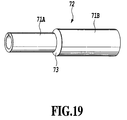
The plastic optical alignment tubular sleeve of
this invention that aligns ferrules of different
diameters has the construction in which left and right
thick hollow cylindrical sleeves with different inner
diameters and different thicknesses are joined at the
central joint part. Fig. 19 shows an external view of
the plastic optical alignment tubular sleeve 72 for
conversion connectors of this invention. In this
tubular sleeve 72, a cylindrical sleeve for an MU-type
ferrule 71A formed of a small-diameter thick hollow
cylinder and a cylindrical sleeve for an SC-type
ferrule 71B formed of a thick hollow cylinder larger
in diameter than the former are joined together at a
joint part 73.
The SC-type ferrule 2.499 mm in outer diameter
has an allowable gauge retention force of 0.2-0.6 kgf
whereas the MU-type small-diameter ferrule 1.249 mm in
outer diameter has an allowable gauge retention force
of 0.1-0.25 kgf, smaller than that of the SC-type
ferrule.
The gauge retention force of the tubular sleeve
is determined by the inner diameter and thickness.
Hence, to maintain high reliability of the plastic
optical alignment tubular sleeve in the conversion
connector requires controlling the inner diameter and
thickness of the cylindrical sleeves, into which
ferrules are inserted, to appropriate values to
realize a proper gauge retention force required of
each ferrule.
When ferrules are inserted into the plastic
optical alignment tubular sleeve, the tubular sleeve
elastically deforms causing a stress in the sleeve.
Multiplying this stress with a friction coefficient of
the material can determine the gauge retention force.
First, consider a case in which an SC-type
ferrule 2.499 mm in outer diameter is inserted into
plastic tubular sleeves with a variety of inner
diameters.
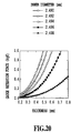
The relation between the gauge retention force
produced and the thickness of the plastic tubular
sleeve is shown in Fig. 20. The allowable gauge
retention force of the SC-type ferrule is in the range
of between 0.2 kgf and 0.6 kgf. From Fig. 20 it is
seen that the plastic tubular sleeve that meets this
requirement needs to have an inner diameter of
approximately 2.490 mm to 2.498 mm and a thickness of
about 0.3 mm to 0.8 mm.
Next, consider a case where an MU-type ferrule
1.249 mm in outer diameter is inserted into plastic
tubular sleeves with a variety of inner diameters.
The relation between the gauge retention force
generated and the thickness of the plastic tubular
sleeve is shown in Fig. 21. The allowable gauge
retention force of the MU-type ferrule is in the range
of 0.1-0.25 kgf. From Fig. 21 it is seen that the
plastic tubular sleeve that meets this requirement
needs to have an inner diameter of approximately 1.246
mm to 1.248 mm and a thickness of about 0.2 mm to 0.3
mm.
The plastic optical alignment tubular sleeve for
conversion connector of this invention that aligns
ferrules of different diameters is made by selecting
an appropriate range of inner diameter and thickness
described above and combining left and right thick
hollow cylindrical sleeves 71A, 71B with different
inner diameters and different thicknesses. The left
and right cylindrical sleeves 71A, 71B are coaxial,
and their centers are aligned at the central part of
the sleeve.
In practice, it is important to provide an air
escape, as by forming a gutter in the inner surface of
the plastic optical alignment tubular sleeve 72 for
conversion connector along its length. For this
purpose, the plastic optical alignment tubular sleeve
72 for conversion connector of this invention has a
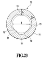
basic cross-sectional geometry, as shown in Figs. 23-25,
in which there are at least three planes 76 inside
that contact the ferrule, thus allowing for a precise
holding of the ferrule and providing a space for air
escape.
That is, in the cross section of the plastic
optical alignment tubular sleeve 72 for conversion
connector shown in Fig. 23, an outer circumferential
surface 74 is a circumferential surface of a cylinder.
Inside the outer circumferential cylinder there is a
hollow space 75 extending longitudinally therethrough,
into which a ferrule is inserted. The inner wall
surface of the hollow space 75 has at least three
planes 76.
These planes 76 are coaxial with the outer
circumferential cylinder and are arranged such that
the diameter d of a virtual cylinder 77 inscribed in
the planes 76 is smaller than the outer diameter of
the inserted ferrule. Surfaces 78 connecting the
planes 76 may have a simple geometry, for example, in
the form of an outer circumferential surface of a
cylinder, as long as their distance from the center of
the inscribing virtual cylinder 77 is set larger than
the radius of the virtual cylinder 77. In this
embodiment, as described above, the ferrule holding
surface required to have a high precision is formed of
planes 76 and the surfaces connecting these planes 76
are kept out of contact with the ferrule by making
their distance from the center larger than that of the
ferrule holding surface.
The cross section, shown in Fig. 24, of the
plastic optical alignment tubular sleeve 72 for
conversion connector according to this invention is
similar to that of the plastic optical alignment
tubular sleeve 72 for conversion connector of Fig. 23,
except that the surfaces 78 connecting the three
planes 76 are planar.
The cross section, shown in Fig. 25, of the
plastic optical alignment tubular sleeve 72 for
conversion connector of this invention connects the
planes 76 with the cylindrical circumferential
surfaces 78 as in Fig. 23, except that there are
transition portions 79 at the connecting parts.
(5) Structure of Joint Part
The structure of the joint part 73, which is
situated at an intermediate portion of the plastic
optical alignment tubular sleeve 72 with different
dimensions, is very important in securing a good
connection between different-diameter ferrules.
The interior of the plastic optical alignment
tubular sleeve 72 for conversion connector of this
invention is shown in Fig. 26.
The joint part 73 for joining the left and right
cylindrical sleeves 71A, 71B with different inner
diameters and different thicknesses begins at the end
of the left small-diameter cylindrical sleeve 71A in
Fig. 26 and expands in diameter along a slope as it
extends over a predetermined length toward the right
large-diameter cylindrical sleeve 71B and then merges
with it. The thickness of the thinnest portion of the
joint part 73 is the same as that of the small-diameter
cylindrical sleeve 71A, which is in the range
of about 0.2 mm to 0.3 mm.
The magnitude of slope of the joint part 73 is
related with the stress that is generated in the
plastic tubular sleeve 72 when different-diameter
ferrules are inserted.
Inside the plastic tubular sleeve 72 for
conversion connector, the different-diameter ferrules
are joined at the end of the cylindrical sleeve 71B of
a larger inner diameter. The stress that occurs in
the plastic tubular sleeve 72 becomes maximum at the
end of the sleeve 71B near the connecting point. The
relation between the maximum stress occurring in the
plastic tubular sleeve 72 and the angle of elevation
of the joint part 73 as seen from the small-diameter
cylindrical sleeve 71A is shown in Fig. 22.
From Fig. 22 it is understood that the maximum
stress decreases as the angle of elevation decreases.
Applying an excessively large stress continuously is
not desirable considering a resulting creep. However,
setting too small an angle of elevation results in a
longer joint part 73 and therefore an increased
dimension of the conversion connector, which is not
desirable. Therefore, the angle of elevation of the
joint part 73 as seen from the small-diameter
cylindrical sleeve 71A should be set in the range of
30-75 degrees, or preferably 45-60 degrees.
With the above construction, it is possible to
provide the joint part 73 with a sufficient thickness
and guarantee the mechanical strength and creep
resistance required by this invention.
In the following, we will describe preferred
embodiments that exhibit advantageous characteristics
unique to the invention. It should be noted, however,
that the invention is not limited to these embodiments.
[Embodiment 6]
First, the following resin compounds were
prepared.
| Cresol novolak type epoxy resin | 100 parts by weight |
| Phenol novolak type curing agent | 100 parts by weight |
| Silica powder (average particle diameter 10 µm) | 500 parts by weight |
The flexural modulus of this resin compound was
2,100 kg/mm
2 in ASTM standard. The anisotropy of the
resin was evaluated by the ratio of mold shrinkage
factors in the direction along the flow of the resin
and the direction at right angles thereto and found to
be as low as 1.0. The resin compound formed in this
manner was injection-molded into a plastic optical
alignment tubular sleeve 72 for conversion connector
shaped as shown in Fig. 19 with the dimensions of
Table 9.
| Dimensions of the tubular sleeve for conversion connector in embodiment 6 |
| Item | Dimensional tolerance |
| Cylindrical sleeve for SC ferrule |
| Inner diameter d | 2.496 ± 0.0005 mm |
| Thickness t1 | 0.600 ± 0.005 mm |
| Thickness t2 | 0.500 ± 0.005 mm |
| Length | 5.7 ± 0.005 mm |
| Cylindrical sleeve for MU ferrule |
| Inner diameter | 1.2475 ± 0.0005 mm |
| Thickness t1 | 0.370 ± 0.005 mm |
| Thickness t2 | 0.270 ± 0.005 mm |
| Length | 2.9 ± 0.005 mm |
| Length of joint part | 0.5 ± 0.005 mm |
| Angle of elevation of joint part | 60° |
The conditions of injection molding were as shown
in Table 10. The inner diameter error, thickness
error and roundness error of the moldings are all
within 1 µm and the smoothness of the inner surface
was within ±0.1 µm.
| Conditions of injection molding |
| Item | Conditions |
| Drying of resin | Stored at room temperature in dry atmosphere |
| Cylinder temperature | Rear portion | 35°C |
| Intermediate portion |
| | 50°C |
| Nozzle portion | 86°C |
| Mold temperature | 180°C |
| Injection pressure |
| | 400 kg/cm2 |
| Screw backpressure | 80 kg/cm2 |
| Retention pressure | 500 kg/cm2 |
| Injection rate | 20 mm/sec |
| Cycling time |
| | 60 seconds |
The measured gauge retention forces of the
tubular sleeve for the SC-type ferrule and MU-type
ferrule were 0.36 kgf and 0.14 kgf, respectively. The
plastic optical alignment tubular sleeve 72
manufactured in this manner was assembled into a
conversion connector, into which the SC- and MU-type
ferrules of zirconia were inserted to measure the
insertion loss and the return loss. The end faces of
the ferrules were polished under the advanced physical
contact (AdPC) polishing conditions. The results are
shown in Figs. 27 and 28, which are satisfactory
characteristics for the connection of single-mode
optical fibers.
Results of various reliability tests are shown in
Table 11. They all meet the target characteristics of
the conversion connector.
| Reliability test results |
| Evaluation item | Test condition | Target characteristic | Test result |
| Mechanical tests | Repetitive attachment/ detachment | 500 times | ΔLi<0.2dB
Lr>40dB | ΔLi<0.2dB
Lr>40dB |
| Vibration |
| | 10 to 55 Hz |
| | Amplitude: 1.5 mm |
| | 2 min/cycle |
| | 60 cycles x |
| | 3 directions |
| Impact | 100 G |
| | Application time: 6 ms |
| | 10 times x 3 |
| | directions |
| Environmental tests | Temperature- humidity cycling | -10 to 65°C | ΔLi<0.2dB
Lr>40dB | ΔLi<0.2dB
Lr>40dB |
| 93% RH |
| 24 h/cycle |
| 20 cycles |
| Temperature cycling | -25 to 70°C |
| 3.5 h/cycle |
| 100 cycles |
| High temperature storage | 85°C |
| 960 hours |
| Low temperature storage | -25°C |
| 960 hours |
| ΔLi: Variation of insertion loss |
| Lr: Return loss |
The following resin compounds were prepared.
| Polyethersulfone | 100 parts by weight |
| Inorganic filler | 30 parts by weight |
The flexural modulus of this resin compound was 800
kg/mm
2 in ASTM standard. The resin compound formed in
this manner was injection-molded into a plastic
optical
alignment tubular sleeve 72 for conversion
connector shaped as shown in Fig. 19 with the
dimensions of Table 12.
| Dimensions of the tubular sleeve for conversion connector in embodiment 7 |
| Item | Dimensional tolerance |
| Cylindrical sleeve for SC ferrule |
| Inner diameter d | 2.492 ± 0.0005 mm |
| Thickness t1 | 0.500 ± 0.005 mm |
| Thickness t2 | 0.400 ± 0.005 mm |
| Length | 5.7 ± 0.005 mm |
| Cylindrical sleeve for MU ferrule |
| Inner diameter | 1.248 ± 0.0005 mm |
| Thickness t1 | 0.380 ± 0.005 mm |
| Thickness t2 | 0.280 ± 0.005 mm |
| Length | 2.9 ± 0.005 mm |
| Length of joint part | 0.5 ± 0.005 mm |
| Angle of elevation of joint part | 60° |
The conditions of injection molding were as shown
in Table 13. The inner diameter error, thickness
error and roundness error of the moldings are all
within 1 µm and the smoothness of the inner surface
was within ±0.5 µm.
| Conditions of injection molding |
| Item | Conditions |
| Drying of resin | 160°C, 5 hours |
| Cylinder | Rear portion | 360°C |
| temperature | Intermediate portion | 370°C |
| | Nozzle portion | 375°C |
| Mold temperature | 160°C |
| Injection pressure | 1,200 kg/cm2 |
| Screw backpressure | 60 kg/cm2 |
| Retention pressure | 500 kg/cm2 |
| Injection rate | 50 mm/sec |
| Cycling time |
| | 30 seconds |
The measured gauge retention forces of the
tubular sleeve for the SC-type ferrule and MU-type
ferrule were 0.48 kgf and 0.16 kgf, respectively. The
plastic optical alignment tubular sleeve 72
manufactured in this manner was assembled into a
conversion connector, into which the SC- and MU-type
ferrules of zirconia were inserted to measure the
insertion loss and the return loss.
As shown in Table 14, the connection
characteristic of the single-mode optical fibers was
within 0.2 dB on average and the return loss was
higher than 50 dB. These results are satisfactory for
the characteristics of the single-mode optical fibers.
The results of various reliability tests are
shown in Table 14. They satisfy the target
characteristics of the conversion connector, as in the
embodiment 6.
| Results of Embodiments 7 to 10 |
| Evaluation item | Embodiment | 7 | Embodiment 8 | Embodiment 9 | Embodiment 10 |
| Insertion loss | 0.17±0.1dB | 0,14±0,1dB | 0.15±0.1dB | 0.18±0,1dB |
| Return loss | 51±2dB | 50±2dB | 51±2dB | 52±2dB |
| Repetitive attaching/ detaching | ΔLi<0.2dB Lr>40dB | ΔLi<0.2dB Lr>40dB | ΔLi<0.2dB Lr>40dB | ΔLi<0.2dB Lr>40dB |
| Vibration/ impact test |
| Temperature- humidity cycle | ΔLi<0.2dB Lr>40dB | ΔLi<0.2dB Lr>40dB | ΔLi<0.2dB Lr>40dB | ΔLi<0.2dB Lr>40dB |
| Temperature cycle | ΔLi<0.2dB Lr>40dB | ΔLi<0.2dB Lr>40dB | ΔLi<0.2dB Lr>40dB | ΔLi<0.2dB Lr>40dB |
| High temp. storage | ΔLi<0.2dB | ΔLi<0.2dB | ΔLi<0.2dB | ΔLi<0.2dB |
| Low temp. storage | Lr>40dB | Lr>40dB | Lr>40dB | Lr>40dB |
| ΔLi: Variation of insertion loss |
| Lr: Return loss |
Using the resin or resin compound shown in Table
15, a plastic optical alignment tubular sleeve was
manufactured as in the
embodiment 6 and 7. The inner
diameter, thickness and length were set as in the
embodiment 7. The gauge retention forces of the
plastic optical alignment tubular sleeve for the SC-and
MU-type ferrules were within the allowable range.
As shown in Table 14, the connection characteristics
of the single-mode optical fibers are at the same
level as the
embodiment 6 and 7. In various
reliability tests, the necessary characteristics of
the conversion connector were satisfied.
| Resin and resin compound and their characteristics in embodiment 8 to 10 |
| Embodiment | Resin | Additive | flexural modulus |
| 8 | Polyethersulfone | Carbon fiber | 20% | 800 kgf/mm 2 |
| 9 | Polyetherimide | Inorganic filler 40% | 1,200 kgf/mm 2 |
| 10 | Polysulfone | Inorganic filler 30% | 600 kgf/mm2 |
Using the resin of the
embodiment 6, plastic
optical alignment tubular sleeves for conversion
connectors, which were out of an appropriate range as
shown in Table 16, were fabricated by changing the
inner diameter and thickness of the cylindrical sleeve
for the SC-type ferrule and the cylindrical sleeve for
the MU-type small-diameter ferrule. The plastic
optical alignment tubular sleeves manufactured in this
manner were assembled into conversion connectors and
measurements were made of insertion loss and return
loss, and insertion loss variations and return loss in
various reliability tests. The results of
measurements are shown in Table 16. In either of
these samples, the insertion loss and return loss, or
loss variations in the reliability tests were higher
than the target values, indicating that the desirable
characteristics as found in the
embodiment 6 to 10
could not be realized.
| Results of Comparison Example 1 to 5 |
| Evaluation Item | Example 1 | Example 2 | Example 3 | Example 4 | Example 5 |
| SC inner dia. | 2.480 mm | 2.492 mm | 2.496 mm | 2.487 mm | 2.496 mm |
| SC thickness t1 | 0.604 mm | 0.310 mm | 1.050 mm | 0.830 mm | 0.762 mm |
| SC thickness t2 | 0.504 mm | 0.210 mm | 0.950 mm | 0.730 mm | 0.662 mm |
| MU inner dia. | 1.247 mm | 1.246 mm | 1.246 mm | 1.238 mm | 1.246 mm |
| MU thickness t1 | 0.360 mm | 0.380 mm | 0.375 mm | 0.380 mm | 0.207 mm |
| MU thickness t2 | 0.260 mm | 0.280 mm | 0.275 mm | 0.280 mm | 0.107 mm |
| Insertion loss | 0.67±0.4d B | 1.06±0.3d B | 1.15±0.3d B | 0.74±0.4d B | 2.06±0.6d B |
| Return loss | 45±2dB | 48±2dB | 43±2dB | 44±2dB | 48±2dB |
| Repetitive attaching/ deteching | ΔLi<0.2dB Lr>40dB | ΔLi<0.2dB Lr>40dB | ΔLi<0.2dB Lr>40dB | ΔLi<0.2dB Lr>40dB | ΔLi<0.2dB Lr>40dB |
| Vibration/ impact test |
| Temp.-humidity cycling | ΔLi<0.2dB Lr>40dB | ΔLi=0.3dB Lr>40dB | ΔLi<0.2dB Lr>40dB | ΔLi<0.2dB Lr>40dB | ΔLi<0.2dB Lr>40dB |
| Temp. cycling | ΔLi=0.3dB Lr>40dB | ΔLi=0.5dB Lr>40dB | ΔLi=0.3dB Lr>40dB | ΔLi=0.6dB Lr>40dB | ΔLi=0.4dB Lr>40dB |
| High temp. storage | ΔLi=0.5dB Lr>40dB | ΔLi<0.2dB Lr>40dB | ΔLi<0.2dB Lr>40dB | ΔLi<0.2dB Lr>40dB | ΔLi<0.2dB Lr>40dB |
| Low temp. storage |
| ΔLi: Variation of insertion loss |
| Lr: Return loss |
The present invention has been described in detail
with respect to preferred embodiments, and it will now
be apparent from the foregoing to those skilled in the
art that changes and modifications may be made without
departing from the invention in its broader aspect,
and it is the intention, therefore, in the apparent
claims to cover all such changes and modifications as
fall within the true spirit of the invention.