EP1099921A2 - Process for the delivery of a cryogenically separated gas mixture component at a variable rate - Google Patents
Process for the delivery of a cryogenically separated gas mixture component at a variable rate Download PDFInfo
- Publication number
- EP1099921A2 EP1099921A2 EP00309785A EP00309785A EP1099921A2 EP 1099921 A2 EP1099921 A2 EP 1099921A2 EP 00309785 A EP00309785 A EP 00309785A EP 00309785 A EP00309785 A EP 00309785A EP 1099921 A2 EP1099921 A2 EP 1099921A2
- Authority
- EP
- European Patent Office
- Prior art keywords
- liquid
- distillation column
- storage vessel
- stream
- oxygen
- Prior art date
- Legal status (The legal status is an assumption and is not a legal conclusion. Google has not performed a legal analysis and makes no representation as to the accuracy of the status listed.)
- Granted
Links
Images




Classifications
-
- F—MECHANICAL ENGINEERING; LIGHTING; HEATING; WEAPONS; BLASTING
- F25—REFRIGERATION OR COOLING; COMBINED HEATING AND REFRIGERATION SYSTEMS; HEAT PUMP SYSTEMS; MANUFACTURE OR STORAGE OF ICE; LIQUEFACTION SOLIDIFICATION OF GASES
- F25J—LIQUEFACTION, SOLIDIFICATION OR SEPARATION OF GASES OR GASEOUS OR LIQUEFIED GASEOUS MIXTURES BY PRESSURE AND COLD TREATMENT OR BY BRINGING THEM INTO THE SUPERCRITICAL STATE
- F25J3/00—Processes or apparatus for separating the constituents of gaseous or liquefied gaseous mixtures involving the use of liquefaction or solidification
- F25J3/02—Processes or apparatus for separating the constituents of gaseous or liquefied gaseous mixtures involving the use of liquefaction or solidification by rectification, i.e. by continuous interchange of heat and material between a vapour stream and a liquid stream
- F25J3/04—Processes or apparatus for separating the constituents of gaseous or liquefied gaseous mixtures involving the use of liquefaction or solidification by rectification, i.e. by continuous interchange of heat and material between a vapour stream and a liquid stream for air
- F25J3/04763—Start-up or control of the process; Details of the apparatus used
- F25J3/04866—Construction and layout of air fractionation equipments, e.g. valves, machines
- F25J3/04872—Vertical layout of cold equipments within in the cold box, e.g. columns, heat exchangers etc.
-
- F—MECHANICAL ENGINEERING; LIGHTING; HEATING; WEAPONS; BLASTING
- F25—REFRIGERATION OR COOLING; COMBINED HEATING AND REFRIGERATION SYSTEMS; HEAT PUMP SYSTEMS; MANUFACTURE OR STORAGE OF ICE; LIQUEFACTION SOLIDIFICATION OF GASES
- F25J—LIQUEFACTION, SOLIDIFICATION OR SEPARATION OF GASES OR GASEOUS OR LIQUEFIED GASEOUS MIXTURES BY PRESSURE AND COLD TREATMENT OR BY BRINGING THEM INTO THE SUPERCRITICAL STATE
- F25J3/00—Processes or apparatus for separating the constituents of gaseous or liquefied gaseous mixtures involving the use of liquefaction or solidification
- F25J3/02—Processes or apparatus for separating the constituents of gaseous or liquefied gaseous mixtures involving the use of liquefaction or solidification by rectification, i.e. by continuous interchange of heat and material between a vapour stream and a liquid stream
- F25J3/04—Processes or apparatus for separating the constituents of gaseous or liquefied gaseous mixtures involving the use of liquefaction or solidification by rectification, i.e. by continuous interchange of heat and material between a vapour stream and a liquid stream for air
- F25J3/04006—Providing pressurised feed air or process streams within or from the air fractionation unit
- F25J3/04078—Providing pressurised feed air or process streams within or from the air fractionation unit providing pressurized products by liquid compression and vaporisation with cold recovery, i.e. so-called internal compression
- F25J3/04084—Providing pressurised feed air or process streams within or from the air fractionation unit providing pressurized products by liquid compression and vaporisation with cold recovery, i.e. so-called internal compression of nitrogen
-
- F—MECHANICAL ENGINEERING; LIGHTING; HEATING; WEAPONS; BLASTING
- F25—REFRIGERATION OR COOLING; COMBINED HEATING AND REFRIGERATION SYSTEMS; HEAT PUMP SYSTEMS; MANUFACTURE OR STORAGE OF ICE; LIQUEFACTION SOLIDIFICATION OF GASES
- F25J—LIQUEFACTION, SOLIDIFICATION OR SEPARATION OF GASES OR GASEOUS OR LIQUEFIED GASEOUS MIXTURES BY PRESSURE AND COLD TREATMENT OR BY BRINGING THEM INTO THE SUPERCRITICAL STATE
- F25J3/00—Processes or apparatus for separating the constituents of gaseous or liquefied gaseous mixtures involving the use of liquefaction or solidification
- F25J3/02—Processes or apparatus for separating the constituents of gaseous or liquefied gaseous mixtures involving the use of liquefaction or solidification by rectification, i.e. by continuous interchange of heat and material between a vapour stream and a liquid stream
- F25J3/04—Processes or apparatus for separating the constituents of gaseous or liquefied gaseous mixtures involving the use of liquefaction or solidification by rectification, i.e. by continuous interchange of heat and material between a vapour stream and a liquid stream for air
- F25J3/04006—Providing pressurised feed air or process streams within or from the air fractionation unit
- F25J3/04078—Providing pressurised feed air or process streams within or from the air fractionation unit providing pressurized products by liquid compression and vaporisation with cold recovery, i.e. so-called internal compression
- F25J3/0409—Providing pressurised feed air or process streams within or from the air fractionation unit providing pressurized products by liquid compression and vaporisation with cold recovery, i.e. so-called internal compression of oxygen
-
- F—MECHANICAL ENGINEERING; LIGHTING; HEATING; WEAPONS; BLASTING
- F25—REFRIGERATION OR COOLING; COMBINED HEATING AND REFRIGERATION SYSTEMS; HEAT PUMP SYSTEMS; MANUFACTURE OR STORAGE OF ICE; LIQUEFACTION SOLIDIFICATION OF GASES
- F25J—LIQUEFACTION, SOLIDIFICATION OR SEPARATION OF GASES OR GASEOUS OR LIQUEFIED GASEOUS MIXTURES BY PRESSURE AND COLD TREATMENT OR BY BRINGING THEM INTO THE SUPERCRITICAL STATE
- F25J3/00—Processes or apparatus for separating the constituents of gaseous or liquefied gaseous mixtures involving the use of liquefaction or solidification
- F25J3/02—Processes or apparatus for separating the constituents of gaseous or liquefied gaseous mixtures involving the use of liquefaction or solidification by rectification, i.e. by continuous interchange of heat and material between a vapour stream and a liquid stream
- F25J3/04—Processes or apparatus for separating the constituents of gaseous or liquefied gaseous mixtures involving the use of liquefaction or solidification by rectification, i.e. by continuous interchange of heat and material between a vapour stream and a liquid stream for air
- F25J3/04248—Generation of cold for compensating heat leaks or liquid production, e.g. by Joule-Thompson expansion
- F25J3/04284—Generation of cold for compensating heat leaks or liquid production, e.g. by Joule-Thompson expansion using internal refrigeration by open-loop gas work expansion, e.g. of intermediate or oxygen enriched (waste-)streams
- F25J3/0429—Generation of cold for compensating heat leaks or liquid production, e.g. by Joule-Thompson expansion using internal refrigeration by open-loop gas work expansion, e.g. of intermediate or oxygen enriched (waste-)streams of feed air, e.g. used as waste or product air or expanded into an auxiliary column
- F25J3/04303—Lachmann expansion, i.e. expanded into oxygen producing or low pressure column
-
- F—MECHANICAL ENGINEERING; LIGHTING; HEATING; WEAPONS; BLASTING
- F25—REFRIGERATION OR COOLING; COMBINED HEATING AND REFRIGERATION SYSTEMS; HEAT PUMP SYSTEMS; MANUFACTURE OR STORAGE OF ICE; LIQUEFACTION SOLIDIFICATION OF GASES
- F25J—LIQUEFACTION, SOLIDIFICATION OR SEPARATION OF GASES OR GASEOUS OR LIQUEFIED GASEOUS MIXTURES BY PRESSURE AND COLD TREATMENT OR BY BRINGING THEM INTO THE SUPERCRITICAL STATE
- F25J3/00—Processes or apparatus for separating the constituents of gaseous or liquefied gaseous mixtures involving the use of liquefaction or solidification
- F25J3/02—Processes or apparatus for separating the constituents of gaseous or liquefied gaseous mixtures involving the use of liquefaction or solidification by rectification, i.e. by continuous interchange of heat and material between a vapour stream and a liquid stream
- F25J3/04—Processes or apparatus for separating the constituents of gaseous or liquefied gaseous mixtures involving the use of liquefaction or solidification by rectification, i.e. by continuous interchange of heat and material between a vapour stream and a liquid stream for air
- F25J3/04406—Processes or apparatus for separating the constituents of gaseous or liquefied gaseous mixtures involving the use of liquefaction or solidification by rectification, i.e. by continuous interchange of heat and material between a vapour stream and a liquid stream for air using a dual pressure main column system
- F25J3/04412—Processes or apparatus for separating the constituents of gaseous or liquefied gaseous mixtures involving the use of liquefaction or solidification by rectification, i.e. by continuous interchange of heat and material between a vapour stream and a liquid stream for air using a dual pressure main column system in a classical double column flowsheet, i.e. with thermal coupling by a main reboiler-condenser in the bottom of low pressure respectively top of high pressure column
-
- F—MECHANICAL ENGINEERING; LIGHTING; HEATING; WEAPONS; BLASTING
- F25—REFRIGERATION OR COOLING; COMBINED HEATING AND REFRIGERATION SYSTEMS; HEAT PUMP SYSTEMS; MANUFACTURE OR STORAGE OF ICE; LIQUEFACTION SOLIDIFICATION OF GASES
- F25J—LIQUEFACTION, SOLIDIFICATION OR SEPARATION OF GASES OR GASEOUS OR LIQUEFIED GASEOUS MIXTURES BY PRESSURE AND COLD TREATMENT OR BY BRINGING THEM INTO THE SUPERCRITICAL STATE
- F25J3/00—Processes or apparatus for separating the constituents of gaseous or liquefied gaseous mixtures involving the use of liquefaction or solidification
- F25J3/02—Processes or apparatus for separating the constituents of gaseous or liquefied gaseous mixtures involving the use of liquefaction or solidification by rectification, i.e. by continuous interchange of heat and material between a vapour stream and a liquid stream
- F25J3/04—Processes or apparatus for separating the constituents of gaseous or liquefied gaseous mixtures involving the use of liquefaction or solidification by rectification, i.e. by continuous interchange of heat and material between a vapour stream and a liquid stream for air
- F25J3/04472—Processes or apparatus for separating the constituents of gaseous or liquefied gaseous mixtures involving the use of liquefaction or solidification by rectification, i.e. by continuous interchange of heat and material between a vapour stream and a liquid stream for air using the cold from cryogenic liquids produced within the air fractionation unit and stored in internal or intermediate storages
- F25J3/04496—Processes or apparatus for separating the constituents of gaseous or liquefied gaseous mixtures involving the use of liquefaction or solidification by rectification, i.e. by continuous interchange of heat and material between a vapour stream and a liquid stream for air using the cold from cryogenic liquids produced within the air fractionation unit and stored in internal or intermediate storages for compensating variable air feed or variable product demand by alternating between periods of liquid storage and liquid assist
- F25J3/04503—Processes or apparatus for separating the constituents of gaseous or liquefied gaseous mixtures involving the use of liquefaction or solidification by rectification, i.e. by continuous interchange of heat and material between a vapour stream and a liquid stream for air using the cold from cryogenic liquids produced within the air fractionation unit and stored in internal or intermediate storages for compensating variable air feed or variable product demand by alternating between periods of liquid storage and liquid assist by exchanging "cold" between at least two different cryogenic liquids, e.g. independently from the main heat exchange line of the air fractionation and/or by using external alternating storage systems
- F25J3/04509—Processes or apparatus for separating the constituents of gaseous or liquefied gaseous mixtures involving the use of liquefaction or solidification by rectification, i.e. by continuous interchange of heat and material between a vapour stream and a liquid stream for air using the cold from cryogenic liquids produced within the air fractionation unit and stored in internal or intermediate storages for compensating variable air feed or variable product demand by alternating between periods of liquid storage and liquid assist by exchanging "cold" between at least two different cryogenic liquids, e.g. independently from the main heat exchange line of the air fractionation and/or by using external alternating storage systems within the cold part of the air fractionation, i.e. exchanging "cold" within the fractionation and/or main heat exchange line
- F25J3/04515—Simultaneously changing air feed and products output
-
- F—MECHANICAL ENGINEERING; LIGHTING; HEATING; WEAPONS; BLASTING
- F25—REFRIGERATION OR COOLING; COMBINED HEATING AND REFRIGERATION SYSTEMS; HEAT PUMP SYSTEMS; MANUFACTURE OR STORAGE OF ICE; LIQUEFACTION SOLIDIFICATION OF GASES
- F25J—LIQUEFACTION, SOLIDIFICATION OR SEPARATION OF GASES OR GASEOUS OR LIQUEFIED GASEOUS MIXTURES BY PRESSURE AND COLD TREATMENT OR BY BRINGING THEM INTO THE SUPERCRITICAL STATE
- F25J3/00—Processes or apparatus for separating the constituents of gaseous or liquefied gaseous mixtures involving the use of liquefaction or solidification
- F25J3/02—Processes or apparatus for separating the constituents of gaseous or liquefied gaseous mixtures involving the use of liquefaction or solidification by rectification, i.e. by continuous interchange of heat and material between a vapour stream and a liquid stream
- F25J3/04—Processes or apparatus for separating the constituents of gaseous or liquefied gaseous mixtures involving the use of liquefaction or solidification by rectification, i.e. by continuous interchange of heat and material between a vapour stream and a liquid stream for air
- F25J3/04763—Start-up or control of the process; Details of the apparatus used
- F25J3/04866—Construction and layout of air fractionation equipments, e.g. valves, machines
- F25J3/04896—Details of columns, e.g. internals, inlet/outlet devices
-
- F—MECHANICAL ENGINEERING; LIGHTING; HEATING; WEAPONS; BLASTING
- F25—REFRIGERATION OR COOLING; COMBINED HEATING AND REFRIGERATION SYSTEMS; HEAT PUMP SYSTEMS; MANUFACTURE OR STORAGE OF ICE; LIQUEFACTION SOLIDIFICATION OF GASES
- F25J—LIQUEFACTION, SOLIDIFICATION OR SEPARATION OF GASES OR GASEOUS OR LIQUEFIED GASEOUS MIXTURES BY PRESSURE AND COLD TREATMENT OR BY BRINGING THEM INTO THE SUPERCRITICAL STATE
- F25J2235/00—Processes or apparatus involving steps for increasing the pressure or for conveying of liquid process streams
- F25J2235/02—Processes or apparatus involving steps for increasing the pressure or for conveying of liquid process streams using a pump in general or hydrostatic pressure increase
-
- F—MECHANICAL ENGINEERING; LIGHTING; HEATING; WEAPONS; BLASTING
- F25—REFRIGERATION OR COOLING; COMBINED HEATING AND REFRIGERATION SYSTEMS; HEAT PUMP SYSTEMS; MANUFACTURE OR STORAGE OF ICE; LIQUEFACTION SOLIDIFICATION OF GASES
- F25J—LIQUEFACTION, SOLIDIFICATION OR SEPARATION OF GASES OR GASEOUS OR LIQUEFIED GASEOUS MIXTURES BY PRESSURE AND COLD TREATMENT OR BY BRINGING THEM INTO THE SUPERCRITICAL STATE
- F25J2235/00—Processes or apparatus involving steps for increasing the pressure or for conveying of liquid process streams
- F25J2235/42—Processes or apparatus involving steps for increasing the pressure or for conveying of liquid process streams the fluid being nitrogen
-
- F—MECHANICAL ENGINEERING; LIGHTING; HEATING; WEAPONS; BLASTING
- F25—REFRIGERATION OR COOLING; COMBINED HEATING AND REFRIGERATION SYSTEMS; HEAT PUMP SYSTEMS; MANUFACTURE OR STORAGE OF ICE; LIQUEFACTION SOLIDIFICATION OF GASES
- F25J—LIQUEFACTION, SOLIDIFICATION OR SEPARATION OF GASES OR GASEOUS OR LIQUEFIED GASEOUS MIXTURES BY PRESSURE AND COLD TREATMENT OR BY BRINGING THEM INTO THE SUPERCRITICAL STATE
- F25J2245/00—Processes or apparatus involving steps for recycling of process streams
- F25J2245/02—Recycle of a stream in general, e.g. a by-pass stream
-
- F—MECHANICAL ENGINEERING; LIGHTING; HEATING; WEAPONS; BLASTING
- F25—REFRIGERATION OR COOLING; COMBINED HEATING AND REFRIGERATION SYSTEMS; HEAT PUMP SYSTEMS; MANUFACTURE OR STORAGE OF ICE; LIQUEFACTION SOLIDIFICATION OF GASES
- F25J—LIQUEFACTION, SOLIDIFICATION OR SEPARATION OF GASES OR GASEOUS OR LIQUEFIED GASEOUS MIXTURES BY PRESSURE AND COLD TREATMENT OR BY BRINGING THEM INTO THE SUPERCRITICAL STATE
- F25J2290/00—Other details not covered by groups F25J2200/00 - F25J2280/00
- F25J2290/62—Details of storing a fluid in a tank
Definitions
- the present invention pertains to the field of cryogenic gas separation, and in particular to a process for the delivery of oxygen at a variable flow rate from a distillation column system.
- Storing product in the liquid phase however, also has at least one disadvantage. Since the product is required in the vapour phase by the customer, the liquid must be vaporized in accordance with variable demand rates. Since oxygen often is vaporized by heat exchange with an incoming warm stream, such as air, the variable rate of oxygen vaporization produces a variable rate of liquid feed to the distillation columns. Such variations constitute disturbances which can affect oxygen product purity.
- US-A-5,265,429 (Dray) teaches a variation on Darredeau whereby only a portion of the liquid air is directed to storage during periods of high oxygen production, and liquid air is transferred from storage to the main liquid air circuit during periods of low oxygen production. In either event, the storage vessel must operate at a pressure greater than that of the distillation system.
- US-A-5,526,647 (Grenier) teaches the use of a storage vessel for liquid air that is maintained at pressures substantially greater than the pressure of the distillation system.
- the disadvantages of storing the liquid air at pressures greater than that of the distillation system depend on the degree to which the pressure is greater.
- the pressure of the main liquid air stream often is 200 psia (1.4 MPa) to 1200 psia (8.3 MPa). If the liquid air storage pressure is maintained at that of the incoming liquid air, the storage vessel must be capable of withstanding high pressure and consequently is expensive to construct. If the liquid air storage pressure is less than that of the main air, then the fluid entering the storage vessel may produce vapour upon pressure reduction. This flash vapour must be routed to the distillation system at a variable rate, since the liquid air flow sent to the storage vessel is variable.
- US-A-5,084,081 (Rohde) teaches a method of withdrawing and storing a nitrogen-rich liquid and oxygen-enriched bottoms from the higher pressure column at a variable rate and introducing streams of the nitrogen-rich liquid and the oxygen-enriched bottoms at a constant rate to the lower pressure column. This maintains constant rates in the lower pressure column but allows flow variations in the higher pressure column.
- the system taught by this patent requires three storage vessels - - one for liquid nitrogen, one for liquid oxygen, and one for liquid oxygen-enriched bottoms.
- the present invention is a process for the delivery of oxygen at variable flow rates from a distillation system.
- the invention provides a process for separation of a gaseous mixture of at least two components by cryogenic distillation to deliver a separated component at a variable flow rate from a distillation column system having at least one distillation column while essentially maintaining the flow rates within the distillation column system at the levels when delivering the separated component at an average delivery rate, said process comprising:
- the invention provides an apparatus for separation of a gaseous mixture of at least two components by cryogenic distillation to deliver a separated component at a variable flow rate by a process of the aforementioned aspect, said apparatus comprising:
- the distillation column system usually will have at least a first distillation column operating at a first pressure and a second distillation column operating at a second pressure and the liquid feed is to the first column.
- the invention has particular application to the cryogenic distillation of air; i.e. the gas mixture is air and the separated component is oxygen.
- a third aspect of the invention is a process for delivering oxygen at a variable flow rate.
- the process which has an average oxygen delivery rate, uses a distillation system having at least a first distillation column operating at a first pressure and a second distillation column operating at a second pressure.
- a stream of liquid comprising air components is fed into the first distillation column, wherein at least a portion of the stream of liquid mixes with a liquid descending in the first distillation column, thereby forming a liquid mixture.
- At least a portion of the liquid mixture is transferred from a location above the bottom of the first distillation column to a first storage vessel at least during periods of greater than the average oxygen delivery rate.
- a stream of liquid oxygen is withdrawn from the distillation system and at least a portion of the withdrawn stream of liquid oxygen is transferred to a second storage vessel at least during periods of less than the average oxygen delivery rate. At least a portion of the liquid oxygen is removed from the second storage vessel at least during periods of greater than the average oxygen delivery rate.
- the invention provides an apparatus for delivering oxygen at a variable flow rate by a process as defined in said third aspect, said apparatus comprising:
- the stream of liquid comprising air components suitably has the composition of air.
- the first pressure can be higher or lower than the second pressure.
- the stream of liquid oxygen can be withdrawn at a substantially constant flow rate from one of the first or second distillation columns; and the at least a portion of the liquid oxygen removed at a variable flow rate from the second storage vessel.
- the at least a portion of the liquid mixture transferred from the first distillation column can be withdrawn at substantially the same location within the first distillation column where the stream of liquid is fed into the first distillation column.
- the pressure of the at least a portion of the liquid oxygen removed from the second storage vessel can be increased and the at least a portion of the liquid oxygen having an increased pressure vaporized to form a gaseous oxygen product stream.
- a stream of liquid nitrogen can be withdrawn from the first distillation column and at least a portion of the stream of liquid nitrogen transferred to a third storage vessel. At least a portion of the liquid nitrogen is withdrawn from the third storage vessel as required.
- the stream of liquid nitrogen can be withdrawn at a substantially constant flow rate from the first distillation column; and the at least a portion of the liquid nitrogen withdrawn at a variable flow rate from the third storage vessel.
- the pressure of the at least a portion of the liquid nitrogen removed from the third storage vessel can be increased and the at least a portion of the liquid nitrogen having an increased pressure vaporized to form a gaseous nitrogen product stream.
- the second distillation column operates at a pressure lower than the first pressure.
- a first stream of liquid air is fed into the first distillation column, wherein at least a portion of the first stream of liquid air mixes with a liquid descending in the first distillation column, thereby forming a liquid mixture.
- a second stream of liquid air is fed into the second distillation column. At least a portion of the liquid mixture is transferred from a location above the bottom of the first distillation column to a first storage vessel at least during periods of greater than the average oxygen delivery rate.
- a stream of liquid oxygen is withdrawn from the distillation system and at least a portion of the withdrawn stream of liquid oxygen transferred to a second vessel at least during periods of less than the average oxygen delivery rate.
- At least a portion of the liquid oxygen is removed from the second storage vessel at least during periods of greater than the average oxygen delivery rate.
- the second stream of liquid air can be fed into the second distillation column at a first variable rate; the at least a portion of the liquid mixture fed from the first storage vessel into the second distillation column at a second variable flow rate; and the sum of the first variable flow rate and the second variable flow rate remains substantially constant over time.
- the second distillation column operates at a pressure higher than the first pressure.
- a stream of liquid air is fed into the second distillation column, wherein at least a portion of the stream of liquid air mixes with a first liquid descending in the second distillation column, thereby forming a first liquid mixture.
- At least a portion of the first liquid mixture is transferred from the second distillation column to the first distillation column, wherein at least a portion of the first liquid mixture mixes with a second liquid descending in the first distillation column, thereby forming a second liquid mixture.
- At least a portion of the second liquid mixture is transferred from a location above the bottom of the first distillation column to a first storage vessel at least during periods of greater than the average oxygen delivery rate.
- a stream of liquid oxygen is withdrawn from the distillation system and at least a portion of the withdrawn stream of liquid oxygen transferred to a second storage vessel at least during periods of less than the average oxygen delivery rate. At least a portion of the liquid oxygen is removed from the second storage vessel at least during periods of greater than the average oxygen delivery rate.
- the second distillation column also operates at a pressure higher than the first pressure.
- a stream of liquid air is fed into the first distillation column, wherein at least a portion of the stream of liquid air mixes with a liquid descending in the first distillation column, thereby forming a liquid mixture.
- a second stream of liquid air is fed into the second distillation column. At least a portion of the liquid mixture is transferred from a location above the bottom of the first distillation column to a first storage vessel at least during periods of greater than the average oxygen delivery rate.
- a stream of liquid oxygen is withdrawn from the distillation system and at least a portion of the withdrawn stream of liquid oxygen transferred to a second storage vessel at least during periods of less than the average oxygen delivery rate. At least a portion of the liquid oxygen is removed from the second storage vessel at least during periods of greater than the average oxygen delivery rate.
- the second distillation column also operates at a pressure higher than the first pressure.
- a stream of liquid air is fed into the first distillation column, wherein at least a portion of the stream of liquid air mixes with a liquid descending in the first distillation column, thereby forming a liquid mixture.
- At least a portion of the liquid mixture is transferred from a location above the bottom of the first distillation column to a first storage vessel at least during periods of greater than the average oxygen delivery rate.
- At least a portion of the liquid mixture is withdrawn from the first storage vessel and at least a portion of the liquid mixture withdrawn from the first storage vessel is transferred into the second distillation column at a substantially constant flow rate.
- a stream of liquid oxygen is withdrawn from the distillation system and at least a portion of the withdrawn stream of liquid oxygen is transferred to a second storage vessel at least during periods of less than the average oxygen delivery rate. At least a portion of the liquid oxygen is removed from the second storage vessel at least during periods of greater than the average oxygen delivery rate.
- Another aspect of the present invention is a cryogenic air separation unit using any of the processes of the present invention.
- the present invention provides a cryogenic air separation process, various embodiments of which are illustrated in Figures 1-7.
- the process uses a distillation column system comprising at least a higher pressure column 124 and a lower pressure column 150, wherein the effects of oxygen product flow rate fluctuations on the distillation column system are reduced by maintaining essentially constant flow rates within the columns.
- the process also utilizes a first storage vessel 142 and a second storage vessel 182 and includes the following features in one or more embodiments: liquid oxygen is withdrawn at a substantially constant rate from the distillation column system and at least a portion of the withdrawn liquid oxygen is directed to the second storage vessel 182; liquid oxygen is withdrawn from the second storage vessel at a variable rate and vaporized in a main heat exchanger 112 against an incoming variable flow rate of air which is condensed to form a liquid air stream and then sent directly to the distillation column system; and a liquid stream is withdrawn from the distillation column system from the same location where at least one of the liquid air streams is fed to the distillation column system, and at least a portion of the liquid air is directed to a first storage vessel 142 during periods of higher than average oxygen delivery rate.
- Feed air 100 is compressed in compressor 102 then cleaned and dried in filter/dryer 104 to form pressurized feed stream 106, which is divided into two portions - - stream 110 and stream 126.
- Stream 110 is partially cooled in main heat exchanger 112. A fraction of the partially cooled stream 110 is drawn off as stream 116, and the remainder, stream 122, is further cooled to a temperature near dew point and introduced to the bottom of higher pressure column 124.
- the stream 116 is turbo-expanded in turbine/expander 118 to produce stream 120, which is fed to the lower pressure column 150.
- Stream 126 is further compressed in compressor 128 to produce stream 130, which is cooled and condensed in the main heat exchanger to form stream 132.
- Stream 132 is reduced in pressure by valve 134 to form stream 136, which is fed to the higher pressure column.
- the higher pressure column 124 produces a nitrogen-enriched overhead 158 and an oxygen-enriched bottoms 152.
- the nitrogen-enriched overhead is condensed in reboiler-condenser 160.
- a portion of the condensate 162 is returned to the higher pressure column as reflux and the remainder 166, after being reduced in pressure by valve 194, is sent to the lower pressure column 150 as reflux.
- the oxygen-enriched bottoms 152 after being reduced in pressure by valve 196, is sent to the lower pressure column as a feed.
- a liquid is withdrawn as stream 140 from a collection pot 138 located in the higher pressure column 124.
- the collection pot receives liquid descending from a distillation section above it plus the liquid feed stream 136. Consequently, the withdrawn liquid stream 140 is taken from the same location in the higher pressure column where feed stream 136 enters that column.
- Withdrawn liquid stream 140 is transferred to a first storage vessel 142.
- a liquid stream 144 is withdrawn from the first storage vessel and, after being reduced in pressure by valve 146, stream 144 is fed to the lower pressure column 150 as a feed.
- the lower pressure column 150 produces a nitrogen-rich vapour 172 from the top of the column.
- the nitrogen-rich vapour is warmed in the main heat exchanger 112 and discharged as stream 176.
- Stream 176 may be a desirable product stream or may be a waste from the process.
- Liquid oxygen is withdrawn from the bottom of the lower pressure column as stream 180 and transferred to the second storage vessel 182.
- the liquid oxygen is withdrawn from the second storage vessel 182 as stream 184, pumped (if required) to a desired pressure in pump 186 to form stream 188, and then vaporized and warmed in the main heat exchanger to form a gaseous oxygen product stream 192.
- the flow of stream 180 from the bottom of the lower pressure column 150 exceeds the flow of stream 184, and thus the level in the second storage vessel 182 rises.
- the flow of stream 140 from the higher pressure column 124 is less than the liquid flow of stream 144 to the lower pressure column, and thus the level in the first storage vessel 142 falls.
- the advantage of this embodiment of the present invention over the prior art stems from the addition of all the liquefied air directly to the higher pressure column 124. Since the higher pressure column handles any flash vapour resulting from the pressure let down across valve 134, the need for and size of vapour vents (not shown) from the first storage vessel 142 are significantly reduced from that necessary for a vessel located upstream of the higher pressure column (as in the prior art).
- the proper sizing of the vent lines is much more important during transient and start-up operations than for normal operations, where sub-cooling of the liquid can be used to alleviate some of the vapour produced during depressurization. Malperformance of the vent control would cause pressure or flow fluctuations in the liquid air line which in turn would affect the oxygen delivery pressure.
- the embodiment in Figure 1 has an added advantage in that the first storage vessel 142 need not operate at as high a pressure as would be necessary for storage of liquid upstream of the higher pressure column, thus reducing the cost of the storage vessel.
- FIG. 2 simplified for clarity, illustrates another embodiment of the present invention.
- a fraction of the incoming liquid air may be split off as stream 232, which after being reduced in pressure by valve 234, may be sent directly to the lower pressure column 150.
- the sum of the flow rates of streams 232 and 144 remains constant.
- FIG. 3 simplified for clarity, illustrates another embodiment of the present invention.
- the first storage vessel 142 is maintained at a relatively low pressure.
- Liquid stream 140 is withdrawn from the higher pressure column 124 and reduced in pressure across valve 146 to form stream 348, which is sent to the first storage vessel 142.
- Liquid stream 344 is withdraw at a constant rate from the first storage vessel and directed to the lower pressure column 150.
- a fraction of the incoming liquid stream 132 may be split off as stream 232, which after being reduced in pressure by valve 234, may be sent directly to the lower pressure column. In this event, the flow of stream 344 will vary such that the sum of the flow rates of streams 344 and 232 remains constant.
- This embodiment has the advantage of only requiring low pressure (low cost) storage.
- FIG 4 simplified for clarity, illustrates another embodiment of the present invention.
- the first storage vessel 142 is maintained at a relatively low pressure in the embodiment in Figure 4.
- Liquid stream 140 is withdrawn from the higher pressure column 124, reduced in pressure across valve 146 to form stream 348, and sent to the lower pressure column 150.
- liquid is withdrawn from a collection pot 438 in the lower pressure column as stream 444 and directed to the first storage vessel 142.
- liquid stream 494 is withdrawn from the first storage vessel 142, pumped in pump 496 to form stream 498, and delivered to the lower pressure column.
- This embodiment allows the first storage vessel 142 to operate at near atmospheric pressure.
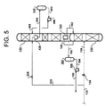
- Figure 5 simplified for clarity, illustrates another embodiment of the present invention.
- the first storage vessel 142 is maintained at a pressure less than that of the lower pressure column 150 in the embodiment in Figure 5.
- This embodiment is useful for small plants which cannot justify the cost of multiple air feeds.
- the remainder of the embodiment in Figure 5 is similar to that of Figure 4.
- liquid is withdrawn from a collection pot 438 in the lower pressure column as stream 444 and directed to the first storage vessel 142.
- liquid stream 494 is withdrawn from the first storage vessel 142, pumped in pump 496 to form stream 498, and delivered to the lower pressure column.
- the embodiment shown in Figure 5 also may be extended to single column systems that do not have a higher pressure column.
- Figure 6 simplified for clarity, illustrates another embodiment of the present invention. This embodiment differs from that of Figure 5 in two ways. First, all of the liquid air stream 132, after being reduced in pressure by valve 634, is fed to the lower pressure column 150 (rather than some being fed to the higher pressure column 124). Second, the liquid stream 698 returned from the first storage vessel 142 is directed to the higher pressure column 124 (in contrast to stream 498 being directed to the lower pressure column in Figure 5).
- all of the liquid oxygen produced from the distillation column system is sent to the second storage vessel 182 operating at essentially the pressure of the lower pressure column 150, and the oxygen is withdrawn from storage and pumped to delivery pressure.
- Other options include: 1) pumping the liquid oxygen from the lower pressure column and directing the liquid oxygen to a high pressure storage; 2) splitting the flow of liquid oxygen from the lower pressure column and passing only the excess liquid oxygen production to the second storage vessel during periods of less-than-average oxygen delivery; and 3) pumping all of the liquid oxygen from the lower pressure column to delivery pressure, then splitting the flow as in option 2).
- nitrogen product is produced from the top of the lower pressure column 150, the top of the higher pressure column 124, or both.
- nitrogen may be withdrawn as either a vapour or a liquid. If withdrawn as a vapour, the nitrogen is warmed in the main heat exchanger 112 and compressed, if necessary, to delivery pressure.
- the nitrogen may be pumped to delivery pressure then vaporized against additional incoming air.
- a third storage vessel 792 for liquid nitrogen as illustrated in Figure 7.
- a portion 790 of the liquid nitrogen stream 166 withdrawn from the higher pressure column 124 may be fed, after being reduced in pressure by valve 788, to the third storage vessel 792.
- Liquid nitrogen is removed subsequently from the third storage vessel as stream 794, pumped to the desired delivery pressure in pump 796 to form stream 798, then vaporized in the main heat exchanger 112 (not shown in Figure 7).
- the level in the third storage vessel 792 rises during periods of lower-than-average nitrogen delivery, and the level will fall during periods of greater-than-average nitrogen delivery.
- the nitrogen storage vessel may operate at any pressure desired.
- the liquid nitrogen stream 166 may be cooled before stream 790 is removed.
Landscapes
- Engineering & Computer Science (AREA)
- Physics & Mathematics (AREA)
- Mechanical Engineering (AREA)
- Thermal Sciences (AREA)
- General Engineering & Computer Science (AREA)
- Health & Medical Sciences (AREA)
- Emergency Medicine (AREA)
- Separation By Low-Temperature Treatments (AREA)
Abstract
Description
Claims (25)
- A process for separation of a gaseous mixture of at least two components by cryogenic distillation to deliver a separated component at a variable flow rate from a distillation column system having at least one distillation column while essentially maintaining the flow rates within the distillation column system at the levels when delivering the separated component at an average delivery rate, said process comprising:withdrawing the separated component as a liquid from the distillation column system at a substantially constant rate;during periods of delivery of the separated component at less than the average delivery rate, storing excess withdrawn liquid separated component in a liquid separated component ("second") storage vessel;during periods of delivery of the separated component at greater than the average delivery rate, supplementing liquid separated component delivery from the distillation column system by withdrawal of liquid separated component from the second storage vessel;vaporizing liquid separated component delivered from the distillation column system and any supplementary liquid separated component from the second storage vessel against condensing feed mixture to form a liquid feed stream;feeding the liquid feed stream to the at least one distillation column to mix with liquid descending said column to form a liquid mixture;during periods of delivery of the separated component at greater than the average delivery rate, withdrawing excess liquid mixture from said column and storing said excess in a liquid mixture ("first") storage vessel; andduring periods of delivery of the separated component at less than the average delivery rate, supplementing liquid mixture feed to the distillation column system by withdrawal of liquid mixture from the first storage vessel and feeding said withdrawn liquid mixture to the distillation column system.
- A process as claimed in Claim 1, wherein the gas mixture is air and the separated component is oxygen.
- A process as claimed in Claim 1, wherein the distillation column system has at least a first distillation column operating at a first pressure and a second distillation column operating at a second pressure and the liquid feed is to the first column.
- A process as claimed in Claim 3, wherein the gas mixture is air and the separated component is oxygen.
- A process for delivering oxygen at a variable flow rate, said process having an average oxygen delivery rate and using a distillation system having at least a first distillation column operating at a first pressure and a second distillation column operating at a second pressure, comprising:characterised in thatfeeding a stream of liquid comprising air components into the first distillation column, wherein at least a portion of said stream of liquid mixes with a liquid descending in the first distillation column, thereby forming a liquid mixture;withdrawing a stream of liquid oxygen from the distillation system;transferring at least a portion of the withdrawn stream of liquid oxygen to a liquid oxygen ("second") storage vessel at least during periods of less than the average oxygen delivery rate; andremoving at least a portion of the liquid oxygen from the second storage vessel at least during periods of greater than the average oxygen delivery rate
at least a portion of said liquid mixture is transferred from a location above the bottom of the first distillation column to a liquid mixture ("first") storage vessel at least during periods of greater than the average oxygen delivery rate. - A process as claimed in Claim 5, wherein the liquid oxygen withdrawn from the second storage vessel is vaporized against condensing air components to provide the liquid feed stream to the first distillation column.
- A process as claimed in Claim 5 or Claim 6, wherein at least a portion of the liquid mixture is withdrawn from the first storage vessel at least during periods of less than average oxygen delivery and fed to the distillation column system to maintain substantially constant the liquid air feed to the system.
- A process as claimed in any one of Claims 5 to 7, wherein:the stream of liquid oxygen is withdrawn at a substantially constant flow rate from one of the first or second distillation columns; andthe at least a portion of the liquid oxygen is removed at a variable flow rate from the second storage vessel.
- A process as claimed in any one of Claims 4 to 8, wherein at least a portion of the liquid mixture transferred from the first distillation column is withdrawn at substantially the same location within the first distillation column where the stream of liquid is fed into the first distillation column.
- A process as claimed in any one of Claims 4 to 9, further comprising:increasing the pressure of the at least a portion of the liquid oxygen removed from the second storage vessel; andvaporizing the at least a portion of the liquid oxygen having an increased pressure to form a gaseous oxygen product stream.
- A process as claimed in any one of the preceding claims, wherein the first pressure is higher than the second pressure.
- A process as claimed in any one of Claims 1 to 11, wherein the first pressure is lower than the second pressure.
- A process as claimed in Claim 11 comprising:feeding a first stream of liquid air into the first distillation column, wherein at least a portion of said first stream of liquid air mixes with a liquid descending in the first distillation column, thereby forming a liquid mixture;feeding a second stream of liquid air into the second distillation column;transferring at least a portion of the liquid mixture from a location above the bottom of the first distillation column to a first storage vessel at least during periods of greater than the average oxygen delivery rate;withdrawing a stream of liquid oxygen from the distillation system;transferring at least a portion of the withdrawn stream of liquid oxygen to a second storage vessel at least during periods of less than the average oxygen delivery rate; andremoving at least a portion of the liquid oxygen from the second storage vessel at least during periods of greater than the average oxygen delivery rate.
- A process as claimed in Claim 13, wherein:the second stream of liquid air is fed into the second distillation column at a first variable flow rate;the at least a portion of the liquid mixture is fed from the first storage vessel into the second distillation column at a second variable flow rate; anda sum of the first variable flow rate and the second variable flow rate remains substantially constant over time.
- A process as claimed in Claim 12 comprising:feeding a stream of liquid air into the second distillation column, wherein at least a portion of said stream of liquid air mixes with a first liquid descending in the second distillation column, thereby forming a first liquid mixture;transferring at least a portion of the first liquid mixture from the second distillation column to the first distillation column, wherein at least a portion of said first liquid mixture mixes with a second liquid descending in the first distillation column, thereby forming a second liquid mixture;transferring at least a portion of the second liquid mixture from a location above the bottom of the first distillation column to a first storage vessel at least during periods of greater than the average oxygen delivery rate;withdrawing a stream of liquid oxygen from the distillation system;transferring at least a portion of the withdrawn stream of liquid oxygen to a second storage vessel at least during periods of less than the average oxygen delivery rate ; andremoving at least a portion of the liquid oxygen from the second storage vessel at least during periods of greater than the average oxygen delivery rate.
- A process as claimed in Claim 12 comprising:feeding a stream of liquid air into the first distillation column, wherein at least a portion of said stream of liquid air mixes with a liquid descending in the first distillation column, thereby forming a liquid mixture;transferring at least a portion of the liquid mixture from a location above the bottom of the first distillation column to a first storage vessel at least during periods of greater than the average oxygen delivery rate;withdrawing a stream of liquid oxygen from the distillation system;transferring at least a portion of the withdrawn stream of liquid oxygen to a second storage vessel at least during periods of less than the average oxygen delivery rate; andremoving at least a portion of the liquid oxygen from the second storage vessel at least during periods of greater than the average oxygen delivery rate.
- A process as claimed in Claim 16, wherein a second stream of liquid air is fed to the second distillation column.
- A process as claimed in Claim 12 comprising:feeding a stream of liquid air into the first distillation column, wherein at least a portion of said stream of liquid air mixes with a liquid descending in the first distillation column, thereby forming a liquid mixture;transferring at least a portion of the liquid mixture from a location above the bottom of the first distillation column to a first storage vessel at least during periods of greater than the average oxygen delivery rate;withdrawing the at least a portion of the liquid mixture from the first storage vessel;transferring the at least a portion of the liquid mixture withdrawn from the first storage vessel into the second distillation column at a substantially constant flow rate;withdrawing a stream of liquid oxygen from the distillation system;transferring at least a portion of the withdrawn stream of liquid oxygen to a second storage vessel at least during periods of less than the average oxygen delivery rate; andremoving at least a portion of the liquid oxygen from the second storage vessel at least during periods of greater than the average oxygen delivery rate.
- A process as claimed in any one of the preceding claims, including the features of Claim 4 or Claim 5, comprising:withdrawing a stream of liquid nitrogen from the first distillation column;transferring at least a portion of the stream of liquid nitrogen to a third storage vessel; andwithdrawing at least a portion of the liquid nitrogen from the third storage vessel.
- A process as claimed in Claim 19, wherein:the stream of liquid nitrogen is withdrawn at a substantially constant flow rate from the first distillation column; andthe at least a portion of the liquid nitrogen is withdrawn at a variable flow rate from the third storage vessel.
- A process as claimed in Claim 20, further comprising:increasing the pressure of the at least a portion of the liquid nitrogen removed from the third storage vessel;vaporizing the at least a portion of the liquid nitrogen having an increased pressure to form a gaseous nitrogen product stream.
- A cryogenic air separation incorporating a process as claimed in any one of the preceding claims.
- An apparatus for separation of a gaseous mixture of at least two components by cryogenic distillation to deliver a separated component at a variable flow rate by a process as defined in Claim 1, said apparatus comprising:a distillation column system (124, 150) having at least one distillation column (124);a first liquid storage vessel (142);a second liquid storage vessel (180);conduit means (180) for withdrawing the separated component as a liquid from the distillation column system at a substantially constant rate;conduit means (180) for delivery of excess withdrawn liquid separated component to said second storage vessel (180) during periods of delivery of the separated component at less than the average delivery rate;conduit means (184) for supplementing liquid separated component delivery from the distillation column system by withdrawal of liquid separated component from the second storage vessel (182) during periods of delivery of the separated component at greater than the average delivery rate;heat exchange means (112) for vaporizing liquid separated component delivered from the distillation column system and any supplementary liquid separated component from the second storage vessel (182) against condensing feed mixture to form a liquid feed stream (132);conduit means (132, 134, 136) for feeding the liquid feed stream to the at least one distillation column (124) to mix with liquid descending said column to form a liquid mixture;conduit means (140) for withdrawing excess liquid mixture from said column and transferring said excess to said first storage vessel (142) during periods of delivery of the separated component at greater than the average delivery rate; andconduit means (144) for feeding said withdrawn liquid mixture from the first storage vessel (142) to the distillation column system to supplement liquid mixture feed to the distillation column system during periods of delivery of the separated component at less than the average delivery rate.
- An apparatus for delivering oxygen at a variable flow rate by a process as defined in Claim 5, said apparatus comprising:a distillation system having at least a first distillation column (124) operating at a first pressure and a second distillation column (150) operating at a second pressure;a first liquid storage vessel (142);a second liquid storage vessel (180);conduit means (132, 134, 136) for feeding a stream of liquid comprising air components into the first distillation column (124) so that at least a portion of said stream of liquid mixes with a liquid descending in the first distillation column, thereby forming a liquid mixture;conduit means (140) for transferring at least a portion of the liquid mixture from a location above the bottom of the first distillation column (124) to the first storage vessel (142) at least during periods of greater than the average oxygen delivery rate;conduit means (180) for withdrawing a stream of liquid oxygen from the distillation system (124, 150);conduit means (180) for transferring at least a portion of the withdrawn stream of liquid oxygen to the second storage vessel (182) at least during periods of less than the average oxygen delivery rate; andconduit means (184) for removing at least a portion of the liquid oxygen from the second storage vessel (182) at least during periods of greater than the average oxygen delivery rate.
- An apparatus as claimed in Claim 23 or Claim 24 adapted to conduct a process as defined in any one of Claims 2 to 4 and 6 to 22.
Applications Claiming Priority (2)
| Application Number | Priority Date | Filing Date | Title |
|---|---|---|---|
| US437896 | 1982-11-01 | ||
| US09/437,896 US6233970B1 (en) | 1999-11-09 | 1999-11-09 | Process for delivery of oxygen at a variable rate |
Publications (3)
| Publication Number | Publication Date |
|---|---|
| EP1099921A2 true EP1099921A2 (en) | 2001-05-16 |
| EP1099921A3 EP1099921A3 (en) | 2001-08-16 |
| EP1099921B1 EP1099921B1 (en) | 2005-06-15 |
Family
ID=23738373
Family Applications (1)
| Application Number | Title | Priority Date | Filing Date |
|---|---|---|---|
| EP00309785A Expired - Lifetime EP1099921B1 (en) | 1999-11-09 | 2000-11-03 | Process for the delivery of a cryogenically separated gas mixture component at a variable rate |
Country Status (6)
| Country | Link |
|---|---|
| US (1) | US6233970B1 (en) |
| EP (1) | EP1099921B1 (en) |
| JP (1) | JP3479277B2 (en) |
| AT (1) | ATE298072T1 (en) |
| CA (1) | CA2325309C (en) |
| DE (1) | DE60020791T2 (en) |
Families Citing this family (3)
| Publication number | Priority date | Publication date | Assignee | Title |
|---|---|---|---|---|
| JP4515225B2 (en) * | 2004-11-08 | 2010-07-28 | 大陽日酸株式会社 | Nitrogen production method and apparatus |
| DE102006000885B3 (en) * | 2006-01-04 | 2007-08-02 | Daimlerchrysler Ag | Method for producing a heat exchanger tube bundle for heat exchangers of electrochemical energy storage devices |
| US11054182B2 (en) | 2018-05-31 | 2021-07-06 | Air Products And Chemicals, Inc. | Process and apparatus for separating air using a split heat exchanger |
Family Cites Families (8)
| Publication number | Priority date | Publication date | Assignee | Title |
|---|---|---|---|---|
| LU35763A1 (en) * | 1957-02-13 | |||
| JPS61190277A (en) * | 1985-02-16 | 1986-08-23 | 大同酸素株式会社 | High-purity nitrogen and oxygen gas production unit |
| DE3913880A1 (en) | 1989-04-27 | 1990-10-31 | Linde Ag | METHOD AND DEVICE FOR DEEP TEMPERATURE DISPOSAL OF AIR |
| FR2652887B1 (en) | 1989-10-09 | 1993-12-24 | Air Liquide | PROCESS AND PLANT FOR THE PRODUCTION OF VARIABLE FLOW GAS OXYGEN BY AIR DISTILLATION. |
| CN1071444C (en) | 1992-02-21 | 2001-09-19 | 普拉塞尔技术有限公司 | Cryogenic air separation system for producing gaseous oxygen |
| FR2716816B1 (en) * | 1994-03-02 | 1996-05-03 | Air Liquide | Method for restarting an auxiliary argon / oxygen separation column by distillation, and corresponding installation. |
| FR2723184B1 (en) | 1994-07-29 | 1996-09-06 | Grenier Maurice | PROCESS AND PLANT FOR THE PRODUCTION OF GAS OXYGEN UNDER PRESSURE WITH VARIABLE FLOW RATE |
| US6182471B1 (en) * | 1999-06-28 | 2001-02-06 | Praxair Technology, Inc. | Cryogenic rectification system for producing oxygen product at a non-constant rate |
-
1999
- 1999-11-09 US US09/437,896 patent/US6233970B1/en not_active Expired - Fee Related
-
2000
- 2000-11-02 CA CA002325309A patent/CA2325309C/en not_active Expired - Fee Related
- 2000-11-03 DE DE60020791T patent/DE60020791T2/en not_active Expired - Lifetime
- 2000-11-03 AT AT00309785T patent/ATE298072T1/en not_active IP Right Cessation
- 2000-11-03 EP EP00309785A patent/EP1099921B1/en not_active Expired - Lifetime
- 2000-11-09 JP JP2000341459A patent/JP3479277B2/en not_active Expired - Fee Related
Also Published As
| Publication number | Publication date |
|---|---|
| US6233970B1 (en) | 2001-05-22 |
| DE60020791D1 (en) | 2005-07-21 |
| DE60020791T2 (en) | 2006-05-18 |
| CA2325309C (en) | 2004-02-03 |
| CA2325309A1 (en) | 2001-05-09 |
| EP1099921B1 (en) | 2005-06-15 |
| ATE298072T1 (en) | 2005-07-15 |
| JP3479277B2 (en) | 2003-12-15 |
| EP1099921A3 (en) | 2001-08-16 |
| JP2001194057A (en) | 2001-07-17 |
Similar Documents
| Publication | Publication Date | Title |
|---|---|---|
| US5082482A (en) | Process and apparatus for the production of gaseous oxygen with a variable flow by air distillation | |
| JP3048373B2 (en) | Method and apparatus for low-temperature separation of air | |
| US5505052A (en) | Process and unit for supplying a gas under pressure to an installation that consumes a constituent of air | |
| EP1782011B1 (en) | Low temperature air separation process for producing pressurized gaseous product | |
| AU719608B2 (en) | Method and device for the production of variable amounts of a pressurized gaseous product | |
| KR100474464B1 (en) | Method and plant for supplying a variable flow rate of a gas from air | |
| JPH0611253A (en) | Cryogenic type air separating method and plant for forming gaseous oxygen | |
| US5572874A (en) | Air separation | |
| US20060021380A1 (en) | Method and installation for production of noble gases and oxygen by means of cryrogenic air distillation | |
| US9546815B2 (en) | Method and device for separating a gas mixture by cryogenic distillation | |
| US6269659B1 (en) | Method and installation for air distillation with production of argon | |
| KR100790911B1 (en) | Method and apparatus for separating air by cryogenic distillation | |
| US6062044A (en) | Method and plant for producing an air gas with a variable flow rate | |
| EP1099921B1 (en) | Process for the delivery of a cryogenically separated gas mixture component at a variable rate | |
| KR20010049391A (en) | Cryogenic distillation system for air separation | |
| US7219514B2 (en) | Method for separating air by cryogenic distillation and installation therefor | |
| US5626036A (en) | Process for the production of oxygen by cryogenic distillation | |
| JP2013525719A (en) | Method and apparatus for separation of air by cryogenic distillation | |
| US5778700A (en) | Method of producing gaseous oxygen at variable rate | |
| EP1099922B1 (en) | Process for the production of intermediate pressure oxygen | |
| US6385996B2 (en) | Process and installation for separation of air by cryogenic distillation | |
| US6141990A (en) | Process and plant for separating air by cryogenic distillation | |
| US6339938B1 (en) | Apparatus and process for separating air by cryogenic distillation | |
| CN113701451B (en) | Method and apparatus for separating air by low-temperature distillation | |
| EP0770840A2 (en) | Air separation |
Legal Events
| Date | Code | Title | Description |
|---|---|---|---|
| PUAI | Public reference made under article 153(3) epc to a published international application that has entered the european phase |
Free format text: ORIGINAL CODE: 0009012 |
|
| AK | Designated contracting states |
Kind code of ref document: A2 Designated state(s): AT BE CH CY DE DK ES FI FR GB GR IE IT LI LU MC NL PT SE TR |
|
| AX | Request for extension of the european patent |
Free format text: AL;LT;LV;MK;RO;SI |
|
| PUAL | Search report despatched |
Free format text: ORIGINAL CODE: 0009013 |
|
| AK | Designated contracting states |
Kind code of ref document: A3 Designated state(s): AT BE CH CY DE DK ES FI FR GB GR IE IT LI LU MC NL PT SE TR |
|
| AX | Request for extension of the european patent |
Free format text: AL;LT;LV;MK;RO;SI |
|
| 17P | Request for examination filed |
Effective date: 20010910 |
|
| AKX | Designation fees paid |
Free format text: AT BE CH CY DE DK ES FI FR GB GR IE IT LI LU MC NL PT SE TR |
|
| 17Q | First examination report despatched |
Effective date: 20030314 |
|
| GRAP | Despatch of communication of intention to grant a patent |
Free format text: ORIGINAL CODE: EPIDOSNIGR1 |
|
| GRAS | Grant fee paid |
Free format text: ORIGINAL CODE: EPIDOSNIGR3 |
|
| GRAA | (expected) grant |
Free format text: ORIGINAL CODE: 0009210 |
|
| AK | Designated contracting states |
Kind code of ref document: B1 Designated state(s): AT BE CH CY DE DK ES FI FR GB GR IE IT LI LU MC NL PT SE TR |
|
| PG25 | Lapsed in a contracting state [announced via postgrant information from national office to epo] |
Ref country code: BE Free format text: LAPSE BECAUSE OF FAILURE TO SUBMIT A TRANSLATION OF THE DESCRIPTION OR TO PAY THE FEE WITHIN THE PRESCRIBED TIME-LIMIT Effective date: 20050615 Ref country code: TR Free format text: LAPSE BECAUSE OF FAILURE TO SUBMIT A TRANSLATION OF THE DESCRIPTION OR TO PAY THE FEE WITHIN THE PRESCRIBED TIME-LIMIT Effective date: 20050615 Ref country code: CH Free format text: LAPSE BECAUSE OF FAILURE TO SUBMIT A TRANSLATION OF THE DESCRIPTION OR TO PAY THE FEE WITHIN THE PRESCRIBED TIME-LIMIT Effective date: 20050615 Ref country code: AT Free format text: LAPSE BECAUSE OF FAILURE TO SUBMIT A TRANSLATION OF THE DESCRIPTION OR TO PAY THE FEE WITHIN THE PRESCRIBED TIME-LIMIT Effective date: 20050615 Ref country code: FI Free format text: LAPSE BECAUSE OF FAILURE TO SUBMIT A TRANSLATION OF THE DESCRIPTION OR TO PAY THE FEE WITHIN THE PRESCRIBED TIME-LIMIT Effective date: 20050615 Ref country code: LI Free format text: LAPSE BECAUSE OF FAILURE TO SUBMIT A TRANSLATION OF THE DESCRIPTION OR TO PAY THE FEE WITHIN THE PRESCRIBED TIME-LIMIT Effective date: 20050615 Ref country code: ES Free format text: LAPSE BECAUSE OF FAILURE TO SUBMIT A TRANSLATION OF THE DESCRIPTION OR TO PAY THE FEE WITHIN THE PRESCRIBED TIME-LIMIT Effective date: 20050615 Ref country code: NL Free format text: LAPSE BECAUSE OF FAILURE TO SUBMIT A TRANSLATION OF THE DESCRIPTION OR TO PAY THE FEE WITHIN THE PRESCRIBED TIME-LIMIT Effective date: 20050615 Ref country code: IT Free format text: LAPSE BECAUSE OF FAILURE TO SUBMIT A TRANSLATION OF THE DESCRIPTION OR TO PAY THE FEE WITHIN THE PRESCRIBED TIME-LIMIT;WARNING: LAPSES OF ITALIAN PATENTS WITH EFFECTIVE DATE BEFORE 2007 MAY HAVE OCCURRED AT ANY TIME BEFORE 2007. THE CORRECT EFFECTIVE DATE MAY BE DIFFERENT FROM THE ONE RECORDED. Effective date: 20050615 |
|
| REG | Reference to a national code |
Ref country code: GB Ref legal event code: FG4D Ref country code: CH Ref legal event code: EP |
|
| REF | Corresponds to: |
Ref document number: 60020791 Country of ref document: DE Date of ref document: 20050721 Kind code of ref document: P |
|
| REG | Reference to a national code |
Ref country code: IE Ref legal event code: FG4D |
|
| PG25 | Lapsed in a contracting state [announced via postgrant information from national office to epo] |
Ref country code: DK Free format text: LAPSE BECAUSE OF FAILURE TO SUBMIT A TRANSLATION OF THE DESCRIPTION OR TO PAY THE FEE WITHIN THE PRESCRIBED TIME-LIMIT Effective date: 20050915 Ref country code: GR Free format text: LAPSE BECAUSE OF FAILURE TO SUBMIT A TRANSLATION OF THE DESCRIPTION OR TO PAY THE FEE WITHIN THE PRESCRIBED TIME-LIMIT Effective date: 20050915 Ref country code: SE Free format text: LAPSE BECAUSE OF FAILURE TO SUBMIT A TRANSLATION OF THE DESCRIPTION OR TO PAY THE FEE WITHIN THE PRESCRIBED TIME-LIMIT Effective date: 20050915 |
|
| PG25 | Lapsed in a contracting state [announced via postgrant information from national office to epo] |
Ref country code: IE Free format text: LAPSE BECAUSE OF NON-PAYMENT OF DUE FEES Effective date: 20051103 Ref country code: CY Free format text: LAPSE BECAUSE OF FAILURE TO SUBMIT A TRANSLATION OF THE DESCRIPTION OR TO PAY THE FEE WITHIN THE PRESCRIBED TIME-LIMIT Effective date: 20051103 |
|
| PG25 | Lapsed in a contracting state [announced via postgrant information from national office to epo] |
Ref country code: PT Free format text: LAPSE BECAUSE OF FAILURE TO SUBMIT A TRANSLATION OF THE DESCRIPTION OR TO PAY THE FEE WITHIN THE PRESCRIBED TIME-LIMIT Effective date: 20051124 |
|
| PG25 | Lapsed in a contracting state [announced via postgrant information from national office to epo] |
Ref country code: MC Free format text: LAPSE BECAUSE OF NON-PAYMENT OF DUE FEES Effective date: 20051130 Ref country code: LU Free format text: LAPSE BECAUSE OF NON-PAYMENT OF DUE FEES Effective date: 20051130 |
|
| NLV1 | Nl: lapsed or annulled due to failure to fulfill the requirements of art. 29p and 29m of the patents act | ||
| REG | Reference to a national code |
Ref country code: CH Ref legal event code: PL |
|
| ET | Fr: translation filed | ||
| PLBE | No opposition filed within time limit |
Free format text: ORIGINAL CODE: 0009261 |
|
| STAA | Information on the status of an ep patent application or granted ep patent |
Free format text: STATUS: NO OPPOSITION FILED WITHIN TIME LIMIT |
|
| 26N | No opposition filed |
Effective date: 20060316 |
|
| REG | Reference to a national code |
Ref country code: IE Ref legal event code: MM4A |
|
| PGFP | Annual fee paid to national office [announced via postgrant information from national office to epo] |
Ref country code: DE Payment date: 20091130 Year of fee payment: 10 |
|
| PGFP | Annual fee paid to national office [announced via postgrant information from national office to epo] |
Ref country code: GB Payment date: 20091007 Year of fee payment: 10 Ref country code: FR Payment date: 20091120 Year of fee payment: 10 |
|
| GBPC | Gb: european patent ceased through non-payment of renewal fee |
Effective date: 20101103 |
|
| REG | Reference to a national code |
Ref country code: FR Ref legal event code: ST Effective date: 20110801 |
|
| REG | Reference to a national code |
Ref country code: DE Ref legal event code: R119 Ref document number: 60020791 Country of ref document: DE Effective date: 20110601 Ref country code: DE Ref legal event code: R119 Ref document number: 60020791 Country of ref document: DE Effective date: 20110531 |
|
| PG25 | Lapsed in a contracting state [announced via postgrant information from national office to epo] |
Ref country code: DE Free format text: LAPSE BECAUSE OF NON-PAYMENT OF DUE FEES Effective date: 20110531 |
|
| PG25 | Lapsed in a contracting state [announced via postgrant information from national office to epo] |
Ref country code: FR Free format text: LAPSE BECAUSE OF NON-PAYMENT OF DUE FEES Effective date: 20101130 |
|
| PG25 | Lapsed in a contracting state [announced via postgrant information from national office to epo] |
Ref country code: GB Free format text: LAPSE BECAUSE OF NON-PAYMENT OF DUE FEES Effective date: 20101103 |