EP1099916A2 - Combustion device - Google Patents
Combustion device Download PDFInfo
- Publication number
- EP1099916A2 EP1099916A2 EP00309446A EP00309446A EP1099916A2 EP 1099916 A2 EP1099916 A2 EP 1099916A2 EP 00309446 A EP00309446 A EP 00309446A EP 00309446 A EP00309446 A EP 00309446A EP 1099916 A2 EP1099916 A2 EP 1099916A2
- Authority
- EP
- European Patent Office
- Prior art keywords
- water
- valve
- drain
- passage
- amount
- Prior art date
- Legal status (The legal status is an assumption and is not a legal conclusion. Google has not performed a legal analysis and makes no representation as to the accuracy of the status listed.)
- Granted
Links
- 238000002485 combustion reaction Methods 0.000 title claims abstract description 39
- XLYOFNOQVPJJNP-UHFFFAOYSA-N water Substances O XLYOFNOQVPJJNP-UHFFFAOYSA-N 0.000 claims abstract description 128
- 239000000446 fuel Substances 0.000 claims abstract description 16
- 238000007599 discharging Methods 0.000 claims abstract description 6
- 239000008399 tap water Substances 0.000 claims description 22
- 235000020679 tap water Nutrition 0.000 claims description 22
- 239000007789 gas Substances 0.000 description 39
- 238000011144 upstream manufacturing Methods 0.000 description 11
- 238000006386 neutralization reaction Methods 0.000 description 10
- 230000001105 regulatory effect Effects 0.000 description 7
- 230000001276 controlling effect Effects 0.000 description 5
- MWUXSHHQAYIFBG-UHFFFAOYSA-N nitrogen oxide Inorganic materials O=[N] MWUXSHHQAYIFBG-UHFFFAOYSA-N 0.000 description 5
- 239000002253 acid Substances 0.000 description 4
- QAOWNCQODCNURD-UHFFFAOYSA-N Sulfuric acid Chemical compound OS(O)(=O)=O QAOWNCQODCNURD-UHFFFAOYSA-N 0.000 description 3
- 230000003472 neutralizing effect Effects 0.000 description 3
- GRYLNZFGIOXLOG-UHFFFAOYSA-N Nitric acid Chemical compound O[N+]([O-])=O GRYLNZFGIOXLOG-UHFFFAOYSA-N 0.000 description 2
- 230000007423 decrease Effects 0.000 description 2
- 238000003780 insertion Methods 0.000 description 2
- 230000037431 insertion Effects 0.000 description 2
- 229910017604 nitric acid Inorganic materials 0.000 description 2
- 230000002093 peripheral effect Effects 0.000 description 2
- 229910052815 sulfur oxide Inorganic materials 0.000 description 2
- 239000012670 alkaline solution Substances 0.000 description 1
- 238000010586 diagram Methods 0.000 description 1
- 238000007865 diluting Methods 0.000 description 1
- 238000003912 environmental pollution Methods 0.000 description 1
- 238000010438 heat treatment Methods 0.000 description 1
- 239000002184 metal Substances 0.000 description 1
- 238000012986 modification Methods 0.000 description 1
- 230000004048 modification Effects 0.000 description 1
- XTQHKBHJIVJGKJ-UHFFFAOYSA-N sulfur monoxide Chemical class S=O XTQHKBHJIVJGKJ-UHFFFAOYSA-N 0.000 description 1
Images

Classifications
-
- F—MECHANICAL ENGINEERING; LIGHTING; HEATING; WEAPONS; BLASTING
- F24—HEATING; RANGES; VENTILATING
- F24H—FLUID HEATERS, e.g. WATER OR AIR HEATERS, HAVING HEAT-GENERATING MEANS, e.g. HEAT PUMPS, IN GENERAL
- F24H8/00—Fluid heaters characterised by means for extracting latent heat from flue gases by means of condensation
- F24H8/006—Means for removing condensate from the heater
-
- F—MECHANICAL ENGINEERING; LIGHTING; HEATING; WEAPONS; BLASTING
- F24—HEATING; RANGES; VENTILATING
- F24H—FLUID HEATERS, e.g. WATER OR AIR HEATERS, HAVING HEAT-GENERATING MEANS, e.g. HEAT PUMPS, IN GENERAL
- F24H1/00—Water heaters, e.g. boilers, continuous-flow heaters or water-storage heaters
-
- Y—GENERAL TAGGING OF NEW TECHNOLOGICAL DEVELOPMENTS; GENERAL TAGGING OF CROSS-SECTIONAL TECHNOLOGIES SPANNING OVER SEVERAL SECTIONS OF THE IPC; TECHNICAL SUBJECTS COVERED BY FORMER USPC CROSS-REFERENCE ART COLLECTIONS [XRACs] AND DIGESTS
- Y02—TECHNOLOGIES OR APPLICATIONS FOR MITIGATION OR ADAPTATION AGAINST CLIMATE CHANGE
- Y02B—CLIMATE CHANGE MITIGATION TECHNOLOGIES RELATED TO BUILDINGS, e.g. HOUSING, HOUSE APPLIANCES OR RELATED END-USER APPLICATIONS
- Y02B30/00—Energy efficient heating, ventilation or air conditioning [HVAC]
Definitions
- the present invention relates to a combustion device such as a hot water supply device or the like, and more particularly to a combustion device for neutralizing, with tap water, an acid drain that is produced from a heat exchanger by a heat exchange with an exhaust gas produced by the combustion of a fuel in a burner.
- the disclosed hot water supply device comprises a water passage 51 having faucets 50 on ends thereof, a water flow switch 51a for detecting a water flow through the water passage 51, a burner 52, a sensible heat exchanger 53, a latent heat exchanger 54, a receptacle 55 disposed below the latent heat exchanger 54 for collecting water condensed in the latent heat exchanger 54, a drain passage 56 for discharging the collected water as a drain, a branch passage 58 branched from the water passage 51 upstream of the sensible heat exchanger 53 and joined to a tank 57 connected to the drain passage 56, and an on-off valve 59 for selectively opening and closing the branch passage 58.
- Water flowing through the water passage 51 is gradually heated by the heat of the exhaust gas from the burner 52 as it passes successively through the sensible heat exchanger 53 and the latent heat exchanger 54.
- the heated water is supplied to the faucets 50.
- the water that flows through the water passage 51 is primarily heated in the sensible heat exchanger 53.
- Water vapour contained in the exhaust gas is condensed in the latent heat exchanger 54 because the water vapouris deprived of latent heat.
- the condensed water is collected by the receptacle 55, and discharged as a drain via the drain passage 56 from the hot water supply device. Since the drain contains nitric acid (HNO 3 ) and sulfuric acid (H 2 SO 4 ) by absorbing nitrogen oxides (NOx) and sulfur oxides (SOx) from the exhaust gas, the drain has an acidity of about pH 4. If the drain is discharged as it is without being neutralized, then it tends to corrode the metal components used as the drain passage 56 and associated parts, deteriorate surrounding concrete structures, and contaminating water, causing environmental pollution. It is therefore necessary to neutralize the drain so that the pH thereof will be in the range of 5 to 9 as provided for according to the drain standards.
- the on-off valve 59 is opened in response to a signal from the water flow switch 51a.
- the on-off valve 59 is opened, a portion of tap water from the water passage 51 flows through the branch passage 58 and the tank 57 and is mixed with the drain flowing through the drain passage 56, thus neutralizing the drain to bring its pH into the range of 5 to 9.
- the drain thus neutralized is discharged from the drain passage 56.
- neutralization used herein covers mixing an alkaline solution with the drain to bring its pH into the range according to the drain standards, and also diluting the drain with water to bring its pH into the range according to the drain standards.
- the amount of tap water flowing through the branch passage 58 may possibly change and become excessive.
- the amount of water flowing through the branch passage 58 increases if the pressure of water in the water passage 51 rises.
- the drain is mixed with a greater amount of water than necessary via the on-off valve 59.
- a combustion device has a burner for combusting a fuel, a water passage for passing water therethrough, a heat exchanger for increasing the temperature of water in the water passage due to a heat exchange with an exhaust gas produced by the burner upon combustion of the fuel, a drain passage for discharging a drain produced when water vapour contained in the exhaust gas is condensed in the heat exchanger, an on-off valve for selectively opening and closing the branch passage, and on-off valve control means for controlling the opening and closing of the on-off valve when the fuel is combusted by the burner.
- the combustion device has a constant-rate valve connected to the branch passage for keeping a rate of flow of water at a substantially constant level in the branch passage irrespective of changes in the pressure of water therein.
- a hot water supply device is provided as a combustion device which is capable of preventing the unduly consumption of tap water that is mixed with an acid drain.
- the on-off valve control means may comprise amount-of-combusted-gas measuring means for measuring an amount of gas combusted by the burner per unit time, and valve-opening-time control means for controlling a time for which the on-off valve is opened depending on the amount of gas combusted by the burner which is measured by the amount-of-combusted-gas measuring means.
- the on-off valve control means may further comprise calculating means for calculating an amount of produced drain based on the amount of gas combusted by the burner which is measured by the amount-of-combusted-gas measuring means, calculating an amount of tap water to be mixed with the drain in order to bring the pH of the drain into a range of 5 to 9, based on the calculated amount of produced drain, and calculating a time for which the on-off valve is opened based on the calculated amount of tap water.
- the on-off valve control means When the amount of gas combusted by the burner increases, the on-off valve control means extends the time for which the on-off valve is opened, and when the amount of gas combusted by the burner decreases, the on-off valve control means shortens the time for which the on-off valve is opened. In this manner, the amount of tap water supplied via the branch passage and mixed with the drain increases or decreases.
- the constant-rate valve is effective to prevent the rate of flow of water in the branch passage from being varied regardless of changes in the pressure of water in the water passage. Consequently, the ratio of the amount of tap water mixed with the produced drain to the amount of the produced drain is maintained at a substantially constant level.
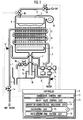
- a hot water supply device as a combustion device according to the present invention has a water passage 1 extending through a combustion chamber x, a burner 2 disposed in the combustion chamber x for combusting a fuel such as a gas, a sensible heat exchanger 3 disposed below the burner 2 in the combustion chamber x, and a latent heat exchanger 4 disposed below the sensible heat exchanger 3 in the combustion chamber x.
- the hot water supply device also has a drain passage 5 for collecting and discharging water (drain) condensed in the latent heat exchanger 4 and dropped onto a bottom wall of the combustion chamber x, and a controller 6 for controlling operation of the hot water supply device.
- the drain passage 5 includes a primary tank 5a for holding the drain, and a secondary tank 5b for receiving a drain overflow from the primary tank 5a.
- the water passage 1 extends through the latent heat exchanger 4 and the sensible heat exchanger 3 such that water flowing through the water passage 1 first passes through the latent heat exchanger 4 and then passes through the sensible heat exchanger 3.
- a bypass passage 7 is branched from the water passage 1 upstream of the latent heat exchanger 4 and joined to the water passage 1 downstream of the sensible heat exchanger 3, in bypassing relation to the combustion chamber x.
- the bypass passage 7 has a bypass flow regulating valve 7a for regulating the rate of flow of water in the bypass passage 7.
- a branch passage 8 is branched from the water passage 1 upstream of the bypass passage 7, and extends into the secondary tank 5b of the drain passage 5 for supplying water from the water passage 1 to the secondary tank 5b.
- the branch passage 8 has an on-off valve 8a and a constant-rate valve 8b for keeping the rate of flow at a constant level irrespective of changes in the pressure of water in the branch passage 8.
- the water passage 1 is associated with an incoming water temperature sensor la positioned upstream of the point where the branch passage 8 is branched from the water passage 1, a flow meter lb positioned near the point where the bypass passage 7 is branched from the water passage 1, a main flow regulating valve lc disposed upstream of the point where the bypass passage 7 is branched from the water passage 1 and downstream of the point where the branch passage 8 is branched from the water passage 1, an outgoing water temperature sensor 1d positioned downstream of the sensible heat exchanger 3, and a faucet le connected to a downstream end of the water passage 1.
- a gas supply passage 9 which has a main solenoid-operated valve 9a for selectively opening and closing the gas supply passage 9, and a gas regulating valve 9b for regulating the rate of flow of a gas supplied to the burner 2.
- the combustion chamber x houses therein a combustion fan 10 for supplying combustion air to the burner 2, and has an exhaust port 11 for discharging an exhaust gas produced by the burner 2.
- the controller 6 comprises a combustion control unit 12 for controlling the amount of gas combusted by the burner 2, and an on-off valve control unit 13 for controlling the opening and closing of the on-off valve 8a.
- the on-off valve control unit 13 has an amount-of-combusted-gas measuring unit 14, a calculating unit 15, a valve-opening-time control unit 16, and a timer 17.
- the amount-of-combusted-gas measuring unit 14 measures the amount of gas combusted by the burner 2 which is controlled by the combustion control unit 12.
- the calculating unit 15 calculates an amount of produced drain, an amount of tap water to be mixed with the drain, and a time for which the on-off valve 8a is to be opened, i.e., a valve opening time, from the amount of gas measured by the amount-of-combusted-gas measuring unit 14.
- the valve-opening-time control unit 16 controls a time in which to open the on-off valve 8a based on the valve opening time calculated by the calculating unit 15.
- the timer 17 controls the opening and closing of the on-off valve 8a based on the time controlled by the valve-opening-time control unit 16.
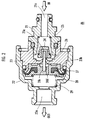
- FIG. 2 shows the constant-rate valve 8b in detail.
- the constant-rate valve 8b has a first cylindrical body 21 disposed in an upstream position, i.e., a right position in FIG. 2, and a second cylindrical body 22 disposed in a downstream position.
- the first cylindrical body 21 and the second cylindrical body 22 are coupled to each other by a substantially disk-shaped intermediate member 23.
- the first cylindrical body 21 has an inlet passage 21a defined coaxially therein, and houses a valve element 24 disposed in the inlet passage 21a and a first spring 25 disposed in the inlet passage 21a for normally urging the valve element 24 downstream, i.e., to the left in FIG. 2.
- a rod valve 26 is mounted on the distal end of the valve element 24 and inserted through a water passageway hole 23a defined centrally in the intermediate member 23 with a clearance around the rod valve 26.
- the second cylindrical body 22 has an outlet passage 22a defined coaxially therein, and houses a diaphragm 27 of rubber disposed in the outlet passage 22a, a diaphragm holder 28 disposed in the outlet passage 22a and holding the diaphragm 27, and a second spring 29 disposed in the outlet passage 22a for normally urging the diaphragm holder 28 upstream, i.e., to the right in FIG. 2.
- the diaphragm 27 has an outer peripheral edge clamped in position between a flange 23b of increased diameter projecting downstream from the intermediate member 23 and the second cylindrical body 22.
- the diaphragm holder 28 has an insertion hole 28c defined centrally therein which receives a tip end of the rod valve 26, and a through hole 28d defined therein at an off-center position, i.e., radially off the insertion hole 28c.
- the rate of flow of water in the branch passage 8 can be maintained at a constant level irrespective of changes in the water pressure upstream of the constant-rate valve 8b.
- the constant-rate valve 8b is arranged to allow 200 cc of water per 1 minute to flow therethrough in order to adjust the pH of the drain to a reference pH range from 5 to 9 even when the amount of produced drain is maximum.
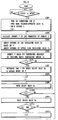
- the controller 6 determines whether the faucet le is opened or not, or specifically, whether tap water flows at a given rate in the water passage 1 and the flow meter lb outputs a predetermined flow rate signal or not, in STEP1. If the flow meter 1b outputs a predetermined flow rate signal and hence the faucet le is judged as being opened in STEP1 (YES), then the combustion fan 10 is actuated, the main solenoid-operated valve 9a is opened, and an igniter (not shown) is operated to cause the burner 2 to start burning the supplied gas in STEP2. In STEP2, a neutralization flag F indicative of whether the drain is being neutralized or not is set to "0".
- the calculating unit 15 calculates an amount P of gas to be combusted by the burner 2 which is required to supply hot water at a temperature preset by a remote control unit (not shown) that is used with the hot water supply device, in STEP3. Specifically, the calculating unit 15 calculates an amount P of gas to be combusted by the burner 2 from the product of a temperature rise, which is represented by the difference between the preset temperature of the hot water and the temperature of incoming water measured by the incoming water temperature sensor la, and the rate of flow of water measured by the flow meter lb.
- the combustion control unit 12 adjusts the opening of the gas regulating valve 9b based on the amount P of gas to be combusted by the burner 2 which has been calculated by the calculating unit 15 in STEP4.
- the combustion control unit 12 also adjusts the opening of the gas regulating valve 9b to control the amount P of gas combusted by the burner 2 in a feedback loop in order to equalize the temperature of hot water measured by the outgoing water temperature sensor ld with the temperature preset by the remote control unit, in STEP5.
- the controller 6 determines whether the drain is being neutralized or not based on the neutralization flag F in STEP6. If the drain is not being neutralized, i.e., if the neutralization flag F is "0" in STEP6 (YES), then the calculating unit 15 calculates an amount of tap water required to adjust the pH of the drain to a reference pH range from 5 to 9, and a time t for which the on-off valve 8a is opened, i.e., a valve opening time t, per minute required to mix the calculated amount of tap water with the drain, in STEP7.
- the controller 6 sets a measured time T of the timer 16 to "0" and also sets the neutralization flag F to "1" in STEP8. Thereafter, the on-off valve 8a is opened in STEP9. If the measured time T of the timer 16 is equal to the valve opening time t in STEP10 (YES), then the on-off valve 8a is closed to interrupt the neutralization of the drain with tap water in STEP11. If the measured time T of the timer 16 reaches 1 minute in STEP12 (YES), then the controller 6 sets the neutralization flag F to "0" in STEP13.
- the combustion control unit 12 closes the main solenoid-operated valve 9a and turns off the combustion fan 10. Therefore, the combustion in the burner 2 is stopped. However, since a certain amount of drain is continuously produced for a certain period of time after the combustion in the burner 2 is stopped, the on-off valve control unit 13 closes the on-off valve 8a upon elapse of the above certain period of time.
- the rate of flow of water in the branch passage 8 is kept at a constant level by the constant-rate valve 8b. Therefore, the rate of tap water supplied from the branch passage 8 to the secondary tank 5b until the measured time T of the timer 17 reaches the valve opening time t is prevented from varying due to changes in the pressure of water in the water passage 1. Consequently, even if the pressure of water in the branch passage 8 increases due to a pressure buildup in the water passage 1, the rate of flow of water in the branch passage 8 does not increase, but is maintained at a constant level.
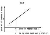
- the drain When the drain is being neutralized, i.e., when the neutralization, flag F is "1", and the on-off valve 8a is cpen, if the temperature preset by the remote control unit for the hot water is changed to a different setting, then the amount P of gas combusted by the burner 2 is changed (see STEP3). At this time, the amount Q of the produced drain is also changed. However, the valve opening time t is also changed based on the changed amount P of gas combusted by the burner 2 as shown in FIG. 3 (see STEP7). Therefore, the drain whose amount is changed is mixed with an amount of tap water that is suitable for neutralizing the drain.
- the hot water supply device is capable of keeping the pH of the drain at the above certain value.
- the above embodiment of the present invention has been described as being applied to the neutralization of a drain discharged from a hot water supply device.
- the principles of the present invention are also applicable to the neutralization of a drain discharged from any of various combustion devices such as a heating boiler, which produce an acid drain from a heat exchanger due to the combustion of a fuel in a burner.
- the fuel combusted by the burner 2 is a gas in the illustrated embodiment, it may be any fuel such as light oil or the like insofar as the produced drain is acid.
Landscapes
- Engineering & Computer Science (AREA)
- Physics & Mathematics (AREA)
- Thermal Sciences (AREA)
- Chemical & Material Sciences (AREA)
- Combustion & Propulsion (AREA)
- Mechanical Engineering (AREA)
- General Engineering & Computer Science (AREA)
- Instantaneous Water Boilers, Portable Hot-Water Supply Apparatuses, And Control Of Portable Hot-Water Supply Apparatuses (AREA)
- Details Of Fluid Heaters (AREA)
- Control Of Combustion (AREA)
Abstract
Description
- The present invention relates to a combustion device such as a hot water supply device or the like, and more particularly to a combustion device for neutralizing, with tap water, an acid drain that is produced from a heat exchanger by a heat exchange with an exhaust gas produced by the combustion of a fuel in a burner.
- One example of combustion devices is a hot water supply device as disclosed in Japanese laid-open utility model publication No. 5-19703, for example. As disclosed in FIG. 5 of the accompanying drawings, the disclosed hot water supply device comprises a
water passage 51 having faucets 50 on ends thereof, a water flow switch 51a for detecting a water flow through thewater passage 51, aburner 52, asensible heat exchanger 53, alatent heat exchanger 54, areceptacle 55 disposed below thelatent heat exchanger 54 for collecting water condensed in thelatent heat exchanger 54, adrain passage 56 for discharging the collected water as a drain, abranch passage 58 branched from thewater passage 51 upstream of thesensible heat exchanger 53 and joined to atank 57 connected to thedrain passage 56, and an on-offvalve 59 for selectively opening and closing thebranch passage 58. - Water flowing through the
water passage 51 is gradually heated by the heat of the exhaust gas from theburner 52 as it passes successively through thesensible heat exchanger 53 and thelatent heat exchanger 54. The heated water is supplied to thefaucets 50. The water that flows through thewater passage 51 is primarily heated in thesensible heat exchanger 53. After the water is heated by thesensible heat exchanger 53, it is further heated in thelatent heat exchanger 54 by the exhaust gas whose temperature has been dropped by the heat exchange in thesensible heat exchanger 53. Since the water that flows through thewater passage 51 is heated in two stages, i.e., successively by thesensible heat exchanger 53 and thelatent heat exchanger 54, the thermal efficiency of the exhaust gas is increased. - Water vapour contained in the exhaust gas is condensed in the
latent heat exchanger 54 because the water vapouris deprived of latent heat. The condensed water is collected by thereceptacle 55, and discharged as a drain via thedrain passage 56 from the hot water supply device. Since the drain contains nitric acid (HNO3) and sulfuric acid (H2SO4) by absorbing nitrogen oxides (NOx) and sulfur oxides (SOx) from the exhaust gas, the drain has an acidity of about pH 4. If the drain is discharged as it is without being neutralized, then it tends to corrode the metal components used as thedrain passage 56 and associated parts, deteriorate surrounding concrete structures, and contaminating water, causing environmental pollution. It is therefore necessary to neutralize the drain so that the pH thereof will be in the range of 5 to 9 as provided for according to the drain standards. - To meet such a requirement, when the hot water supply device supplies hot water, the on-off
valve 59 is opened in response to a signal from the water flow switch 51a. When the on-offvalve 59 is opened, a portion of tap water from thewater passage 51 flows through thebranch passage 58 and thetank 57 and is mixed with the drain flowing through thedrain passage 56, thus neutralizing the drain to bring its pH into the range of 5 to 9. The drain thus neutralized is discharged from thedrain passage 56. The term "neutralization" used herein covers mixing an alkaline solution with the drain to bring its pH into the range according to the drain standards, and also diluting the drain with water to bring its pH into the range according to the drain standards. - However, even when the
burner 52 burns the fuel at a constant rate and the drain is produced in a constant quantity, the amount of tap water flowing through thebranch passage 58 may possibly change and become excessive. For example, though it is sufficient to mix a constant amount of tap water with the drain when the drain is produced in a constant quantity, the amount of water flowing through thebranch passage 58 increases if the pressure of water in thewater passage 51 rises. When the amount of water flowing through thebranch passage 58 increases, the drain is mixed with a greater amount of water than necessary via the on-offvalve 59. - According to the present invention, a combustion device has a burner for combusting a fuel, a water passage for passing water therethrough, a heat exchanger for increasing the temperature of water in the water passage due to a heat exchange with an exhaust gas produced by the burner upon combustion of the fuel, a drain passage for discharging a drain produced when water vapour contained in the exhaust gas is condensed in the heat exchanger, an on-off valve for selectively opening and closing the branch passage, and on-off valve control means for controlling the opening and closing of the on-off valve when the fuel is combusted by the burner.
- In an embodiment of the present invention, the combustion device has a constant-rate valve connected to the branch passage for keeping a rate of flow of water at a substantially constant level in the branch passage irrespective of changes in the pressure of water therein.
- According to the present invention, a hot water supply device is provided as a combustion device which is capable of preventing the unduly consumption of tap water that is mixed with an acid drain.
- Even if the pressure of water in the branch passage increases due to a pressure buildup in the water passage, the rate of flow of water in the branch passage does not increase, but is maintained at a constant level. As a result, when the pressure of water in the water passage rises, a greater amount of tap water than necessary to neutralize the drain is prevented from being mixed with the drain.
- The on-off valve control means may comprise amount-of-combusted-gas measuring means for measuring an amount of gas combusted by the burner per unit time, and valve-opening-time control means for controlling a time for which the on-off valve is opened depending on the amount of gas combusted by the burner which is measured by the amount-of-combusted-gas measuring means.
- The on-off valve control means may further comprise calculating means for calculating an amount of produced drain based on the amount of gas combusted by the burner which is measured by the amount-of-combusted-gas measuring means, calculating an amount of tap water to be mixed with the drain in order to bring the pH of the drain into a range of 5 to 9, based on the calculated amount of produced drain, and calculating a time for which the on-off valve is opened based on the calculated amount of tap water.
- When the amount of gas combusted by the burner increases, the on-off valve control means extends the time for which the on-off valve is opened, and when the amount of gas combusted by the burner decreases, the on-off valve control means shortens the time for which the on-off valve is opened. In this manner, the amount of tap water supplied via the branch passage and mixed with the drain increases or decreases. The constant-rate valve is effective to prevent the rate of flow of water in the branch passage from being varied regardless of changes in the pressure of water in the water passage. Consequently, the ratio of the amount of tap water mixed with the produced drain to the amount of the produced drain is maintained at a substantially constant level.
- The above and other features and advantages of the present invention will become apparent from the following description when taken in conjunction with the accompanying drawings which illustrate a preferred embodiment of the present invention by way of example.
-
- FIG. 1 is a schematic cross-sectional view, partly in block form, of a hot water supply device as a combustion device according to the present invention;
- FIG. 2 is a cross-sectional view of a constant-rate valve used in the hot water supply device shown in FIG. 1;
- FIG. 3 is a diagram showing the relationship between the amount Q of a produced drain, the time t for which an on-off valve is opened, and the amount P of a fuel combusted by a burner;
- FIG. 4 is a flowchart of an operation sequence of the combustion device according to the present invention; and
- FIG. 5 is a schematic cross-sectional view of a conventional hot water supply device as a combustion device.
-
- As shown in FIG. 1, a hot water supply device as a combustion device according to the present invention has a
water passage 1 extending through a combustion chamber x, aburner 2 disposed in the combustion chamber x for combusting a fuel such as a gas, asensible heat exchanger 3 disposed below theburner 2 in the combustion chamber x, and a latent heat exchanger 4 disposed below thesensible heat exchanger 3 in the combustion chamber x. The hot water supply device also has adrain passage 5 for collecting and discharging water (drain) condensed in the latent heat exchanger 4 and dropped onto a bottom wall of the combustion chamber x, and acontroller 6 for controlling operation of the hot water supply device. Thedrain passage 5 includes aprimary tank 5a for holding the drain, and asecondary tank 5b for receiving a drain overflow from theprimary tank 5a. - The
water passage 1 extends through the latent heat exchanger 4 and thesensible heat exchanger 3 such that water flowing through thewater passage 1 first passes through the latent heat exchanger 4 and then passes through thesensible heat exchanger 3. Abypass passage 7 is branched from thewater passage 1 upstream of the latent heat exchanger 4 and joined to thewater passage 1 downstream of thesensible heat exchanger 3, in bypassing relation to the combustion chamber x. Thebypass passage 7 has a bypassflow regulating valve 7a for regulating the rate of flow of water in thebypass passage 7. Abranch passage 8 is branched from thewater passage 1 upstream of thebypass passage 7, and extends into thesecondary tank 5b of thedrain passage 5 for supplying water from thewater passage 1 to thesecondary tank 5b. Thebranch passage 8 has an on-offvalve 8a and a constant-rate valve 8b for keeping the rate of flow at a constant level irrespective of changes in the pressure of water in thebranch passage 8. Thewater passage 1 is associated with an incoming water temperature sensor la positioned upstream of the point where thebranch passage 8 is branched from thewater passage 1, a flow meter lb positioned near the point where thebypass passage 7 is branched from thewater passage 1, a main flow regulating valve lc disposed upstream of the point where thebypass passage 7 is branched from thewater passage 1 and downstream of the point where thebranch passage 8 is branched from thewater passage 1, an outgoing water temperature sensor 1d positioned downstream of thesensible heat exchanger 3, and a faucet le connected to a downstream end of thewater passage 1. - To the
burner 2, there is connected a gas supply passage 9 which has a main solenoid-operatedvalve 9a for selectively opening and closing the gas supply passage 9, and agas regulating valve 9b for regulating the rate of flow of a gas supplied to theburner 2. The combustion chamber x houses therein acombustion fan 10 for supplying combustion air to theburner 2, and has anexhaust port 11 for discharging an exhaust gas produced by theburner 2. - The
controller 6 comprises acombustion control unit 12 for controlling the amount of gas combusted by theburner 2, and an on-offvalve control unit 13 for controlling the opening and closing of the on-offvalve 8a. The on-offvalve control unit 13 has an amount-of-combusted-gas measuring unit 14, a calculatingunit 15, a valve-opening-time control unit 16, and atimer 17. The amount-of-combusted-gas measuring unit 14 measures the amount of gas combusted by theburner 2 which is controlled by thecombustion control unit 12. The calculatingunit 15 calculates an amount of produced drain, an amount of tap water to be mixed with the drain, and a time for which the on-offvalve 8a is to be opened, i.e., a valve opening time, from the amount of gas measured by the amount-of-combusted-gas measuring unit 14. The valve-opening-time control unit 16 controls a time in which to open the on-offvalve 8a based on the valve opening time calculated by the calculatingunit 15. Thetimer 17 controls the opening and closing of the on-offvalve 8a based on the time controlled by the valve-opening-time control unit 16. - FIG. 2 shows the constant-
rate valve 8b in detail. As shown in FIG. 2, the constant-rate valve 8b has a firstcylindrical body 21 disposed in an upstream position, i.e., a right position in FIG. 2, and a secondcylindrical body 22 disposed in a downstream position. The firstcylindrical body 21 and the secondcylindrical body 22 are coupled to each other by a substantially disk-shapedintermediate member 23. - The first
cylindrical body 21 has aninlet passage 21a defined coaxially therein, and houses avalve element 24 disposed in theinlet passage 21a and afirst spring 25 disposed in theinlet passage 21a for normally urging thevalve element 24 downstream, i.e., to the left in FIG. 2. Arod valve 26 is mounted on the distal end of thevalve element 24 and inserted through awater passageway hole 23a defined centrally in theintermediate member 23 with a clearance around therod valve 26. - The second
cylindrical body 22 has anoutlet passage 22a defined coaxially therein, and houses adiaphragm 27 of rubber disposed in theoutlet passage 22a, adiaphragm holder 28 disposed in theoutlet passage 22a and holding thediaphragm 27, and asecond spring 29 disposed in theoutlet passage 22a for normally urging thediaphragm holder 28 upstream, i.e., to the right in FIG. 2. Thediaphragm 27 has an outer peripheral edge clamped in position between a flange 23b of increased diameter projecting downstream from theintermediate member 23 and the secondcylindrical body 22. Thediaphragm holder 28 has aninsertion hole 28c defined centrally therein which receives a tip end of therod valve 26, and a throughhole 28d defined therein at an off-center position, i.e., radially off theinsertion hole 28c. - Water flows downstream into the
inlet passage 21a, passes through the clearance around therod valve 26 in thewater passageway hole 23a in theintermediate member 23, then through the throughhole 28d in thediaphragm holder 28, and is discharged downstream from theoutlet passage 22a. - When the pressure of water flowing into the
inlet passage 21a rises, thediaphragm 27 with its outer peripheral edge fixed in position is elastically deformed downstream, displacing thediaphragm holder 28 downstream against the bias of thesecond spring 29. Thevalve element 24 moves toward thewater passageway hole 23a under the bias of thefirst spring 25, restricting the rate of flow of water in the clearance around therod valve 26 in thewater passageway hole 23a. - When the pressure of water flowing into the
inlet passage 21a then drops, thediaphragm 27 is elastically deformed upstream, and thediaphragm holder 28 moves upstream under the bias of thesecond spring 29. Thevalve element 24 also moves upstream away from thewater passageway hole 23a against the bias of thefirst spring 25. Thus, the rate of flow of water in the clearance around therod valve 26 in thewater passageway hole 23a increases. - In this manner, the rate of flow of water in the
branch passage 8 can be maintained at a constant level irrespective of changes in the water pressure upstream of the constant-rate valve 8b. In this embodiment, the constant-rate valve 8b is arranged to allow 200 cc of water per 1 minute to flow therethrough in order to adjust the pH of the drain to a reference pH range from 5 to 9 even when the amount of produced drain is maximum. - Operation of the hot water supply device will be described below with reference to FIG. 4.
- First, the
controller 6 determines whether the faucet le is opened or not, or specifically, whether tap water flows at a given rate in thewater passage 1 and the flow meter lb outputs a predetermined flow rate signal or not, in STEP1. If the flow meter 1b outputs a predetermined flow rate signal and hence the faucet le is judged as being opened in STEP1 (YES), then thecombustion fan 10 is actuated, the main solenoid-operatedvalve 9a is opened, and an igniter (not shown) is operated to cause theburner 2 to start burning the supplied gas in STEP2. In STEP2, a neutralization flag F indicative of whether the drain is being neutralized or not is set to "0". - The calculating
unit 15 calculates an amount P of gas to be combusted by theburner 2 which is required to supply hot water at a temperature preset by a remote control unit (not shown) that is used with the hot water supply device, in STEP3. Specifically, the calculatingunit 15 calculates an amount P of gas to be combusted by theburner 2 from the product of a temperature rise, which is represented by the difference between the preset temperature of the hot water and the temperature of incoming water measured by the incoming water temperature sensor la, and the rate of flow of water measured by the flow meter lb. - Then, the
combustion control unit 12 adjusts the opening of thegas regulating valve 9b based on the amount P of gas to be combusted by theburner 2 which has been calculated by the calculatingunit 15 in STEP4. - The
combustion control unit 12 also adjusts the opening of thegas regulating valve 9b to control the amount P of gas combusted by theburner 2 in a feedback loop in order to equalize the temperature of hot water measured by the outgoing water temperature sensor ld with the temperature preset by the remote control unit, in STEP5. - The
controller 6 determines whether the drain is being neutralized or not based on the neutralization flag F in STEP6. If the drain is not being neutralized, i.e., if the neutralization flag F is "0" in STEP6 (YES), then the calculatingunit 15 calculates an amount of tap water required to adjust the pH of the drain to a reference pH range from 5 to 9, and a time t for which the on-offvalve 8a is opened, i.e., a valve opening time t, per minute required to mix the calculated amount of tap water with the drain, in STEP7. - Then, the
controller 6 sets a measured time T of thetimer 16 to "0" and also sets the neutralization flag F to "1" in STEP8. Thereafter, the on-offvalve 8a is opened in STEP9. If the measured time T of thetimer 16 is equal to the valve opening time t in STEP10 (YES), then the on-offvalve 8a is closed to interrupt the neutralization of the drain with tap water in STEP11. If the measured time T of thetimer 16reaches 1 minute in STEP12 (YES), then thecontroller 6 sets the neutralization flag F to "0" in STEP13. - If the faucet le is closed and the flow meter 1b stops outputting a predetermined flow rate signal, the
combustion control unit 12 closes the main solenoid-operatedvalve 9a and turns off thecombustion fan 10. Therefore, the combustion in theburner 2 is stopped. However, since a certain amount of drain is continuously produced for a certain period of time after the combustion in theburner 2 is stopped, the on-offvalve control unit 13 closes the on-offvalve 8a upon elapse of the above certain period of time. - According to the present invention, even if the pressure of water in the
water passage 1 varies while the drain is being neutralized by tap water (F = 1) with the on-offvalve 8a being open, the rate of flow of water in thebranch passage 8 is kept at a constant level by the constant-rate valve 8b. Therefore, the rate of tap water supplied from thebranch passage 8 to thesecondary tank 5b until the measured time T of thetimer 17 reaches the valve opening time t is prevented from varying due to changes in the pressure of water in thewater passage 1. Consequently, even if the pressure of water in thebranch passage 8 increases due to a pressure buildup in thewater passage 1, the rate of flow of water in thebranch passage 8 does not increase, but is maintained at a constant level. - As a result, when the pressure of water in the
water passage 1 rises, a greater amount of tap water than necessary to neutralize the drain is prevented from being mixed with the drain. - When the drain is being neutralized, i.e., when the neutralization, flag F is "1", and the on-off
valve 8a is cpen, if the temperature preset by the remote control unit for the hot water is changed to a different setting, then the amount P of gas combusted by theburner 2 is changed (see STEP3). At this time, the amount Q of the produced drain is also changed. However, the valve opening time t is also changed based on the changed amount P of gas combusted by theburner 2 as shown in FIG. 3 (see STEP7). Therefore, the drain whose amount is changed is mixed with an amount of tap water that is suitable for neutralizing the drain. - Consequently, irrespective of changes in the pressure of water in the
water passage 1 and changes in the amount P of gas combusted by theburner 2, the ratio of the amount of tap water mixed with the produced drain to the amount of the produced drain is maintained at a substantially constant level. If the pH of the drain needs to be kept closely to a certain value, e.g., "7", under some severe conditions, then the hot water supply device according to the present invention is capable of keeping the pH of the drain at the above certain value. - The above embodiment of the present invention has been described as being applied to the neutralization of a drain discharged from a hot water supply device. However, the principles of the present invention are also applicable to the neutralization of a drain discharged from any of various combustion devices such as a heating boiler, which produce an acid drain from a heat exchanger due to the combustion of a fuel in a burner. While the fuel combusted by the
burner 2 is a gas in the illustrated embodiment, it may be any fuel such as light oil or the like insofar as the produced drain is acid. - Although a certain preferred embodiment of the present invention has been shown and described in detail, it should be understood that various changes and modifications may be made therein without departing from the scope of the appended claims.
Claims (3)
- A combustion device comprising:a burner for combusting a fuel;a water passage (1) for passing water therethrough;a heat exchanger (3, 4) for increasing the temperature of water in said water passage (1) due to a heat exchange with an exhaust gas produced by said burner upon combustion of the fuel;a drain passage (5) for discharging a drain produced when water vapour contained in the exhaust gas is condensed in said heat exchanger (3, 4);an on-off valve (8a) for selectively opening and closing a branch passage (8);on-off valve control means (6) for controlling the opening and closing of said on-off valve (8a) when the fuel is combusted by said burner; anda constant-rate valve (8b) connected to said branch passage (8) for keeping a rate of flow of water at a substantially constant level in said branch passage (8) irrespective of changes in the pressure of water therein.
- A combustion device according to claim 1,
wherein said on-off valve control means (6) comprises:amount-of-combusted gas measuring means (14) for measuring an amount of gas combusted by said burner per unit time; andvalve-opening-time control means (16) for controlling a time for which said on-off valve (8a) is opened depending on the amount of gas combusted by said burner which is measured by said amount-of-combusted-gas measuring means (14). - A combustion device according to claim 2,
wherein said on-off valve control means (6) further comprises:
calculating means (15) for calculating an amount of produced drain based on the amount of gas combusted by said burner which is measured by said amount-of-combusted gas measuring means (14), calculating an amount of tap water to be mixed with the drain in order to bring the pH of the drain into a range of 5 to 9, based on the calculated amount of produced drain, and calculating a time for which said on-off vvalve (8a) is opened based on the calculated amount of tap water.
Applications Claiming Priority (2)
| Application Number | Priority Date | Filing Date | Title |
|---|---|---|---|
| JP32285299 | 1999-11-12 | ||
| JP32285299A JP2001141302A (en) | 1999-11-12 | 1999-11-12 | Latent heat recovery type water heater |
Publications (3)
| Publication Number | Publication Date |
|---|---|
| EP1099916A2 true EP1099916A2 (en) | 2001-05-16 |
| EP1099916A3 EP1099916A3 (en) | 2002-12-11 |
| EP1099916B1 EP1099916B1 (en) | 2006-01-11 |
Family
ID=18148329
Family Applications (1)
| Application Number | Title | Priority Date | Filing Date |
|---|---|---|---|
| EP00309446A Expired - Lifetime EP1099916B1 (en) | 1999-11-12 | 2000-10-26 | Combustion device |
Country Status (5)
| Country | Link |
|---|---|
| EP (1) | EP1099916B1 (en) |
| JP (1) | JP2001141302A (en) |
| KR (1) | KR100387177B1 (en) |
| CN (1) | CN1153938C (en) |
| DE (1) | DE60025448T2 (en) |
Cited By (1)
| Publication number | Priority date | Publication date | Assignee | Title |
|---|---|---|---|---|
| CN110411036A (en) * | 2019-08-19 | 2019-11-05 | 珠海格力电器股份有限公司 | Wall-mounted furnace water outlet temperature control method, device and equipment and wall-mounted furnace |
Families Citing this family (3)
| Publication number | Priority date | Publication date | Assignee | Title |
|---|---|---|---|---|
| KR100406131B1 (en) * | 2001-09-26 | 2003-11-14 | 주식회사 경동보일러 | Heating System For Using The Solenoid Valve |
| JP3920843B2 (en) * | 2003-12-09 | 2007-05-30 | リンナイ株式会社 | Water heater |
| CN102367990B (en) * | 2011-11-10 | 2014-02-26 | 艾欧史密斯(中国)热水器有限公司 | Constant-temperature condensation gas water heater and control method thereof |
Citations (1)
| Publication number | Priority date | Publication date | Assignee | Title |
|---|---|---|---|---|
| JPH0519703U (en) | 1991-08-22 | 1993-03-12 | 三ツ星ベルト株式会社 | High load transmission belt |
Family Cites Families (5)
| Publication number | Priority date | Publication date | Assignee | Title |
|---|---|---|---|---|
| DE3151418A1 (en) * | 1981-12-24 | 1983-07-07 | Herrmann, Klaus, 5840 Schwerte | Low-temperature heating process, utilising the upper calorific value of fuels |
| CA1201032A (en) * | 1982-10-28 | 1986-02-25 | 633972 Ontario Limited | Condensing furnaces |
| DE4240428A1 (en) * | 1992-12-02 | 1994-06-09 | Ruhrgas Ag | Neutralising exhaust gas condensation - using feed of normal drinking water to condensation collection vessel |
| JPH08173977A (en) * | 1994-12-27 | 1996-07-09 | Tokyo Gas Co Ltd | Wastewater treatment method and apparatus for latent heat recovery type high efficiency boiler |
| JP3589610B2 (en) * | 1999-06-22 | 2004-11-17 | 東京瓦斯株式会社 | Combustion equipment |
-
1999
- 1999-11-12 JP JP32285299A patent/JP2001141302A/en active Pending
-
2000
- 2000-08-17 KR KR10-2000-0047342A patent/KR100387177B1/en not_active Expired - Fee Related
- 2000-10-26 EP EP00309446A patent/EP1099916B1/en not_active Expired - Lifetime
- 2000-10-26 DE DE60025448T patent/DE60025448T2/en not_active Expired - Lifetime
- 2000-11-10 CN CNB001283049A patent/CN1153938C/en not_active Expired - Fee Related
Patent Citations (1)
| Publication number | Priority date | Publication date | Assignee | Title |
|---|---|---|---|---|
| JPH0519703U (en) | 1991-08-22 | 1993-03-12 | 三ツ星ベルト株式会社 | High load transmission belt |
Cited By (1)
| Publication number | Priority date | Publication date | Assignee | Title |
|---|---|---|---|---|
| CN110411036A (en) * | 2019-08-19 | 2019-11-05 | 珠海格力电器股份有限公司 | Wall-mounted furnace water outlet temperature control method, device and equipment and wall-mounted furnace |
Also Published As
| Publication number | Publication date |
|---|---|
| KR20010050092A (en) | 2001-06-15 |
| CN1296156A (en) | 2001-05-23 |
| JP2001141302A (en) | 2001-05-25 |
| EP1099916A3 (en) | 2002-12-11 |
| DE60025448T2 (en) | 2006-08-03 |
| KR100387177B1 (en) | 2003-06-12 |
| EP1099916B1 (en) | 2006-01-11 |
| DE60025448D1 (en) | 2006-04-06 |
| CN1153938C (en) | 2004-06-16 |
Similar Documents
| Publication | Publication Date | Title |
|---|---|---|
| US4688547A (en) | Method for providing variable output gas-fired furnace with a constant temperature rise and efficiency | |
| US8165726B2 (en) | Water heater energy savings algorithm for reducing cold water complaints | |
| US9182159B2 (en) | Water heater and control method therefor | |
| US8635997B2 (en) | Systems and methods for controlling gas pressure to gas-fired appliances | |
| EP0154818A1 (en) | Control system for induced draft combustion | |
| JPS6030406B2 (en) | Method and device for adjusting air/fuel mixture in a combustor having a carburetor tube | |
| EP1063480B1 (en) | Combustion Device | |
| EP1099916B1 (en) | Combustion device | |
| GB2176275A (en) | Apparatus for controlling the temperature of the circulating water in a central heating system | |
| US4695052A (en) | Hot water heating system using a heat consumption meter | |
| JP3763953B2 (en) | Combustion equipment | |
| JPS6144111Y2 (en) | ||
| CN208332702U (en) | A kind of the novel thermoregulating device and gas heater of automatic water-mixing | |
| CA1294344C (en) | Gas-fired furnace control apparatus and method for maintaining an optimum fuel air ratio | |
| RU2331023C1 (en) | Modulated atmospheric gas burner | |
| EP0250667A1 (en) | Control of fluid temperature in a wet central heating system and components suitable for a central heating system | |
| JP2820583B2 (en) | Water heater temperature control device | |
| KR100515111B1 (en) | Combustion device | |
| JPH1026412A (en) | Hot water feeding device | |
| JP2526472B2 (en) | Water heater | |
| EP1710511A2 (en) | Boiler with devices for optimising the supply of hot water for sanitary purposes, and the corresponding method | |
| JPH10281555A (en) | Water heater with bypass valve | |
| KR100291490B1 (en) | Control method of rapid operation of gas boiler | |
| JPH0332932Y2 (en) | ||
| JPH0239167Y2 (en) |
Legal Events
| Date | Code | Title | Description |
|---|---|---|---|
| PUAI | Public reference made under article 153(3) epc to a published international application that has entered the european phase |
Free format text: ORIGINAL CODE: 0009012 |
|
| AK | Designated contracting states |
Kind code of ref document: A2 Designated state(s): AT BE CH CY DE DK ES FI FR GB GR IE IT LI LU MC NL PT SE |
|
| AX | Request for extension of the european patent |
Free format text: AL;LT;LV;MK;RO;SI |
|
| PUAL | Search report despatched |
Free format text: ORIGINAL CODE: 0009013 |
|
| AK | Designated contracting states |
Kind code of ref document: A3 Designated state(s): AT BE CH CY DE DK ES FI FR GB GR IE IT LI LU MC NL PT SE |
|
| AX | Request for extension of the european patent |
Free format text: AL;LT;LV;MK;RO;SI |
|
| 17P | Request for examination filed |
Effective date: 20030416 |
|
| 17Q | First examination report despatched |
Effective date: 20030702 |
|
| AKX | Designation fees paid |
Designated state(s): DE GB NL |
|
| GRAP | Despatch of communication of intention to grant a patent |
Free format text: ORIGINAL CODE: EPIDOSNIGR1 |
|
| GRAS | Grant fee paid |
Free format text: ORIGINAL CODE: EPIDOSNIGR3 |
|
| GRAA | (expected) grant |
Free format text: ORIGINAL CODE: 0009210 |
|
| AK | Designated contracting states |
Kind code of ref document: B1 Designated state(s): DE GB NL |
|
| REF | Corresponds to: |
Ref document number: 60025448 Country of ref document: DE Date of ref document: 20060406 Kind code of ref document: P |
|
| PLBE | No opposition filed within time limit |
Free format text: ORIGINAL CODE: 0009261 |
|
| STAA | Information on the status of an ep patent application or granted ep patent |
Free format text: STATUS: NO OPPOSITION FILED WITHIN TIME LIMIT |
|
| 26N | No opposition filed |
Effective date: 20061012 |
|
| PGFP | Annual fee paid to national office [announced via postgrant information from national office to epo] |
Ref country code: DE Payment date: 20131021 Year of fee payment: 14 Ref country code: GB Payment date: 20131021 Year of fee payment: 14 |
|
| PGFP | Annual fee paid to national office [announced via postgrant information from national office to epo] |
Ref country code: NL Payment date: 20131022 Year of fee payment: 14 |
|
| REG | Reference to a national code |
Ref country code: DE Ref legal event code: R119 Ref document number: 60025448 Country of ref document: DE |
|
| REG | Reference to a national code |
Ref country code: NL Ref legal event code: V1 Effective date: 20150501 |
|
| GBPC | Gb: european patent ceased through non-payment of renewal fee |
Effective date: 20141026 |
|
| PG25 | Lapsed in a contracting state [announced via postgrant information from national office to epo] |
Ref country code: DE Free format text: LAPSE BECAUSE OF NON-PAYMENT OF DUE FEES Effective date: 20150501 Ref country code: GB Free format text: LAPSE BECAUSE OF NON-PAYMENT OF DUE FEES Effective date: 20141026 |
|
| PG25 | Lapsed in a contracting state [announced via postgrant information from national office to epo] |
Ref country code: NL Free format text: LAPSE BECAUSE OF NON-PAYMENT OF DUE FEES Effective date: 20150501 |